RU2145892C1 - Method and biological organ electrostimulation means for correcting functional state of immune system organs - Google Patents
Method and biological organ electrostimulation means for correcting functional state of immune system organsDownload PDFInfo
- Publication number
- RU2145892C1 RU2145892C1RU98119500ARU98119500ARU2145892C1RU 2145892 C1RU2145892 C1RU 2145892C1RU 98119500 ARU98119500 ARU 98119500ARU 98119500 ARU98119500 ARU 98119500ARU 2145892 C1RU2145892 C1RU 2145892C1
- Authority
- RU
- Russia
- Prior art keywords
- output
- counter
- input
- shapers
- electrodes
- Prior art date
Links
- 238000000034methodMethods0.000titleclaimsabstractdescription17
- 210000000056organAnatomy0.000titleclaimsabstractdescription13
- 210000000987immune systemAnatomy0.000titleclaimsabstractdescription12
- 230000005855radiationEffects0.000claimsabstractdescription34
- 210000001035gastrointestinal tractAnatomy0.000claimsabstractdescription15
- 230000005670electromagnetic radiationEffects0.000claimsabstractdescription13
- 239000012780transparent materialSubstances0.000claimsabstractdescription5
- 230000003287optical effectEffects0.000claimsdescription15
- 230000010363phase shiftEffects0.000claimsdescription5
- 210000001835visceraAnatomy0.000claimsdescription3
- 230000000694effectsEffects0.000abstractdescription11
- 230000000638stimulationEffects0.000abstractdescription5
- 239000003814drugSubstances0.000abstractdescription2
- 239000000126substanceSubstances0.000abstract1
- 210000000440neutrophilAnatomy0.000description8
- 241000588724Escherichia coliSpecies0.000description6
- 210000003719b-lymphocyteAnatomy0.000description6
- 230000000968intestinal effectEffects0.000description5
- 241000186000BifidobacteriumSpecies0.000description4
- 241000186660LactobacillusSpecies0.000description4
- 210000001744T-lymphocyteAnatomy0.000description4
- 239000002775capsuleSubstances0.000description4
- 238000010586diagramMethods0.000description4
- 210000003979eosinophilAnatomy0.000description4
- 210000003608feceAnatomy0.000description4
- 230000006870functionEffects0.000description4
- 230000002949hemolytic effectEffects0.000description4
- 230000001900immune effectEffects0.000description4
- 210000000265leukocyteAnatomy0.000description4
- 210000004698lymphocyteAnatomy0.000description4
- 210000001616monocyteAnatomy0.000description4
- 210000004027cellAnatomy0.000description3
- 230000001684chronic effectEffects0.000description3
- 201000010099diseaseDiseases0.000description3
- 208000037265diseases, disorders, signs and symptomsDiseases0.000description3
- 210000000936intestineAnatomy0.000description3
- 238000001126phototherapyMethods0.000description3
- 210000000813small intestineAnatomy0.000description3
- 208000027244DysbiosisDiseases0.000description2
- 241000305071EnterobacteralesSpecies0.000description2
- 241000588769Proteus <enterobacteria>Species0.000description2
- 201000004681PsoriasisDiseases0.000description2
- 210000004369bloodAnatomy0.000description2
- 239000008280bloodSubstances0.000description2
- 210000001185bone marrowAnatomy0.000description2
- 230000008859changeEffects0.000description2
- 206010009887colitisDiseases0.000description2
- 239000013078crystalSubstances0.000description2
- 238000003745diagnosisMethods0.000description2
- 230000007140dysbiosisEffects0.000description2
- 230000002255enzymatic effectEffects0.000description2
- 208000015181infectious diseaseDiseases0.000description2
- 230000002458infectious effectEffects0.000description2
- 230000005764inhibitory processEffects0.000description2
- 244000005706microfloraSpecies0.000description2
- 210000003097mucusAnatomy0.000description2
- 210000001640nerve endingAnatomy0.000description2
- 230000001717pathogenic effectEffects0.000description2
- 231100000915pathological changeToxicity0.000description2
- 230000036285pathological changeEffects0.000description2
- 230000000306recurrent effectEffects0.000description2
- 210000001541thymus glandAnatomy0.000description2
- 208000004998Abdominal PainDiseases0.000description1
- 206010000087Abdominal pain upperDiseases0.000description1
- 208000030090Acute DiseaseDiseases0.000description1
- 206010003550Asthenic conditionsDiseases0.000description1
- 208000017667Chronic DiseaseDiseases0.000description1
- 206010014940EosinopeniaDiseases0.000description1
- 206010014950EosinophiliaDiseases0.000description1
- 208000007882GastritisDiseases0.000description1
- 206010020751HypersensitivityDiseases0.000description1
- 108060003951ImmunoglobulinProteins0.000description1
- 206010025327LymphopeniaDiseases0.000description1
- 201000009053NeurodermatitisDiseases0.000description1
- 208000002193PainDiseases0.000description1
- 208000037273Pathologic ProcessesDiseases0.000description1
- 208000008469Peptic UlcerDiseases0.000description1
- 208000035965Postoperative ComplicationsDiseases0.000description1
- 230000006819RNA synthesisEffects0.000description1
- 208000024799Thyroid diseaseDiseases0.000description1
- 238000010521absorption reactionMethods0.000description1
- 230000002378acidificating effectEffects0.000description1
- 230000001154acute effectEffects0.000description1
- 210000001815ascending colonAnatomy0.000description1
- 208000006673asthmaDiseases0.000description1
- 230000000721bacterilogical effectEffects0.000description1
- 230000004071biological effectEffects0.000description1
- 230000015572biosynthetic processEffects0.000description1
- 230000015556catabolic processEffects0.000description1
- 210000004534cecumAnatomy0.000description1
- 230000004663cell proliferationEffects0.000description1
- 230000003247decreasing effectEffects0.000description1
- 230000007812deficiencyEffects0.000description1
- 238000006731degradation reactionMethods0.000description1
- 206010012601diabetes mellitusDiseases0.000description1
- 230000005714functional activityEffects0.000description1
- 244000005709gut microbiomeSpecies0.000description1
- 208000026278immune system diseaseDiseases0.000description1
- 230000036039immunityEffects0.000description1
- 102000018358immunoglobulinHuman genes0.000description1
- 229940072221immunoglobulinsDrugs0.000description1
- 238000000338in vitroMethods0.000description1
- 208000030603inherited susceptibility to asthmaDiseases0.000description1
- 230000010354integrationEffects0.000description1
- 230000008991intestinal motilityEffects0.000description1
- 230000001678irradiating effectEffects0.000description1
- 210000001630jejunumAnatomy0.000description1
- 238000002647laser therapyMethods0.000description1
- 201000002364leukopeniaDiseases0.000description1
- 231100001022leukopeniaToxicity0.000description1
- 239000007788liquidSubstances0.000description1
- 210000001165lymph nodeAnatomy0.000description1
- 231100001023lymphopeniaToxicity0.000description1
- 210000000713mesenteryAnatomy0.000description1
- 201000006417multiple sclerosisDiseases0.000description1
- 210000005036nerveAnatomy0.000description1
- 230000000771oncological effectEffects0.000description1
- 230000009054pathological processEffects0.000description1
- 230000007170pathologyEffects0.000description1
- 208000011906peptic ulcer diseaseDiseases0.000description1
- 210000001986peyer's patchAnatomy0.000description1
- 230000000886photobiologyEffects0.000description1
- 230000008569processEffects0.000description1
- 208000023504respiratory system diseaseDiseases0.000description1
- 230000003248secreting effectEffects0.000description1
- 230000035807sensationEffects0.000description1
- 208000019116sleep diseaseDiseases0.000description1
- 208000022925sleep disturbanceDiseases0.000description1
- 125000006850spacer groupChemical group0.000description1
- 235000021259spicy foodNutrition0.000description1
- 230000004936stimulating effectEffects0.000description1
- 238000003786synthesis reactionMethods0.000description1
- 230000009885systemic effectEffects0.000description1
- 208000021510thyroid gland diseaseDiseases0.000description1
- 210000001519tissueAnatomy0.000description1
- 231100000331toxicToxicity0.000description1
- 230000002588toxic effectEffects0.000description1
Images

Classifications
- A—HUMAN NECESSITIES
- A61—MEDICAL OR VETERINARY SCIENCE; HYGIENE
- A61N—ELECTROTHERAPY; MAGNETOTHERAPY; RADIATION THERAPY; ULTRASOUND THERAPY
- A61N5/00—Radiation therapy
- A61N5/06—Radiation therapy using light
- A61N5/0601—Apparatus for use inside the body
- A61N5/0603—Apparatus for use inside the body for treatment of body cavities
- A61N2005/0609—Stomach and/or esophagus
- A—HUMAN NECESSITIES
- A61—MEDICAL OR VETERINARY SCIENCE; HYGIENE
- A61N—ELECTROTHERAPY; MAGNETOTHERAPY; RADIATION THERAPY; ULTRASOUND THERAPY
- A61N5/00—Radiation therapy
- A61N5/06—Radiation therapy using light
- A61N2005/0626—Monitoring, verifying, controlling systems and methods
- A61N2005/0629—Sequential activation of light sources
- A—HUMAN NECESSITIES
- A61—MEDICAL OR VETERINARY SCIENCE; HYGIENE
- A61N—ELECTROTHERAPY; MAGNETOTHERAPY; RADIATION THERAPY; ULTRASOUND THERAPY
- A61N5/00—Radiation therapy
- A61N5/06—Radiation therapy using light
- A61N2005/065—Light sources therefor
- A61N2005/0651—Diodes
- A61N2005/0652—Arrays of diodes
- A—HUMAN NECESSITIES
- A61—MEDICAL OR VETERINARY SCIENCE; HYGIENE
- A61N—ELECTROTHERAPY; MAGNETOTHERAPY; RADIATION THERAPY; ULTRASOUND THERAPY
- A61N5/00—Radiation therapy
- A61N5/06—Radiation therapy using light
- A61N2005/0658—Radiation therapy using light characterised by the wavelength of light used
- A61N2005/0662—Visible light
- A61N2005/0663—Coloured light
- A—HUMAN NECESSITIES
- A61—MEDICAL OR VETERINARY SCIENCE; HYGIENE
- A61N—ELECTROTHERAPY; MAGNETOTHERAPY; RADIATION THERAPY; ULTRASOUND THERAPY
- A61N5/00—Radiation therapy
- A61N5/06—Radiation therapy using light
- A61N5/0601—Apparatus for use inside the body
- A61N5/0603—Apparatus for use inside the body for treatment of body cavities
Landscapes
- Radiation-Therapy Devices (AREA)
Abstract
Description
Translated fromRussianИзобретение относится к медицине, а именно к электрофототерапии и предназначено для воздействия на некоторые параметры иммунитета. Может найти применение при лечении острых и хронических заболеваний желудочно-кишечного тракта (ЖКТ), иммунно-дефицитных состояний, дисбактериоза, системных заболеваний (псориаз, нейродермит, ревматизм и т.п.), послеоперационных осложнений, астенических состояний, болезней органов дыхания, лейкопений токсического и инфекционного генеза. The invention relates to medicine, namely to electrophototherapy and is intended to affect some parameters of the immune system. It can be used in the treatment of acute and chronic diseases of the gastrointestinal tract (GIT), immune deficiency conditions, dysbiosis, systemic diseases (psoriasis, neurodermatitis, rheumatism, etc.), postoperative complications, asthenic conditions, respiratory diseases, leukopenia toxic and infectious genesis.
Нарушения иммунной системы лежат в основе возникновения и развития большого ряда патологических процессов - воспалительно-гнойных заболеваний ЛОР-органов, кожи, язвенной болезни, болезней щитовидной железы, рассеянного склероза, ревматизма, псориаза, диатеза, аллергических реакций, сахарного диабета, бронхиальной астмы. Изменение функциональной активности системы иммунитета способствует возникновению инфекционных и онкологических заболеваний. Immune system disorders underlie the emergence and development of a large number of pathological processes - inflammatory-purulent diseases of the ENT organs, skin, peptic ulcer, thyroid disease, multiple sclerosis, rheumatism, psoriasis, diathesis, allergic reactions, diabetes mellitus, bronchial asthma. A change in the functional activity of the immune system contributes to the occurrence of infectious and oncological diseases.
Известен способ для физиотерапевтического облучения светом [1]. Способ включает облучение излучателем, размещенным в автономной капсуле, которую располагают на внешней поверхности биообъекта, или вводят в трубчатый орган с использованием внешних приспособлений. Устройство содержит источник питания, элемент управления, источник света с оптической системой и корпус в виде капсулы. Недостаток способа в том, что перемещение капсулы осуществляется внешним воздействием, что ограничивает возможности применения при введении капсулы внутрь организма. A known method for physiotherapeutic exposure to light [1]. The method includes irradiating an emitter placed in an autonomous capsule, which is placed on the external surface of a biological object, or is introduced into a tubular organ using external devices. The device comprises a power source, a control element, a light source with an optical system and a capsule-shaped housing. The disadvantage of this method is that the movement of the capsule is carried out by external influence, which limits the possibility of application when the capsule is introduced into the body.
Известен электростимулятор [2] , содержащий корпус с электродами, источник питания и микропроцессор (микроЭВМ), формирующий стимулирующие электрические импульсы. Одним из недостатков устройства является недостаточно высокая эффективность воздействия только электрическими импульсами. Другим недостатком электростимуляторa является то, что использование микропроцессора усложняет электрическую схему и повышает стоимость, и приводит либо к необходимости увеличения размера кристалла и, следовательно, всего устройства, либо к дополнительному увеличению стоимости устройства из-за большей степени интеграции кристалла. Known electrical stimulator [2], containing a housing with electrodes, a power source and a microprocessor (microcomputer), forming stimulating electrical impulses. One of the disadvantages of the device is the insufficiently high efficiency of exposure only to electric pulses. Another disadvantage of the electric stimulator is that the use of a microprocessor complicates the electrical circuit and increases the cost, and leads either to the need to increase the size of the crystal and, consequently, the entire device, or to an additional increase in the cost of the device due to the greater degree of integration of the crystal.
Известен способ [3] коррекции параметров иммунитета путем воздействия электрическими сигналами импульсной формы от автономного источника с амплитудой тока не более 50 мА и частотой от 4 Гц до 40 МГц на нервные окончания, находящиеся в ЖКТ, ткани и среды организма. Недостаток этого способа заключается в том, что воздействие электрическими импульсами на состояние иммунной системы осуществляется опосредованно через длинную цепь нервных и гуморальных связей, при нарушении которых в силу разных причин данное воздействие становится невозможным. Этот способ выбран за прототип. A known method [3] correction of immunity parameters by exposure to electrical signals in pulsed form from an autonomous source with a current amplitude of not more than 50 mA and a frequency of 4 Hz to 40 MHz on nerve endings located in the gastrointestinal tract, tissues and body environment. The disadvantage of this method is that the impact of electrical impulses on the state of the immune system is carried out indirectly through a long chain of nerve and humoral bonds, in violation of which, for various reasons, this effect becomes impossible. This method is selected for the prototype.
Известен электростимулятор [4] , наиболее близкий по технической сущности, содержащий корпус с электродами, источник питания, генератор с формирователями пакетов импульсов и коммутатор. Электростимулятор обеспечивает биполярные электрические импульсы на электродах при попадании его в желудочно-кишечный тракт. Недостатком электростимулятора является ограничение его эффективности по причине использования только электрических импульсов. Known electrical stimulator [4], the closest in technical essence, containing a housing with electrodes, a power source, a generator with pulse shapers and a switch. An electrical stimulator provides bipolar electrical impulses on the electrodes when it enters the gastrointestinal tract. The disadvantage of the electric stimulator is the limitation of its effectiveness due to the use of only electrical impulses.
Задачей предлагаемого изобретения является повышение эффективности биологического воздействия на иммунокомпетентные органы. The task of the invention is to increase the effectiveness of biological effects on immunocompetent organs.
Единым техническим результатом, достигаемым при осуществлении заявленной группы изобретений, является непосредственное воздействие электромагнитным излучением оптического диапазона на иммуннокомпетентные органы - пейеровы бляшки и иммунокомпетентные клетки, находящиеся в стенках органов ЖКТ, лимфатические узлы брыжейки, аппендикс. The only technical result achieved in the implementation of the claimed group of inventions is the direct exposure to electromagnetic radiation of the optical range on immunocompetent organs - Peyer's plaques and immunocompetent cells located in the walls of the digestive tract, lymph nodes of the mesentery, appendix.
Указанный технический результат достигается тем, что, как и в известном способе, воздействуют электрическими сигналами импульсной формы от автономного стимулятора на отделы ЖКТ, согласно изобретению дополнительно осуществляют облучение электромагнитным излучением оптического диапазона терапевтически активной дозы. При прохождении отделов тонкого кишечника ЖКТ электромагнитное излучение оптического диапазона воздействует непосредственно на пейеровы бляшки. The specified technical result is achieved by the fact that, as in the known method, they influence the gastrointestinal tract with electric signals of a pulsed form from an autonomous stimulator, according to the invention, the radiation of the optical range of the therapeutically active dose is additionally irradiated with electromagnetic radiation. When passing through the sections of the small intestine of the gastrointestinal tract, electromagnetic radiation of the optical range acts directly on the Peyer's plaques.
Иммунокомпетентные органы включают костный мозг, тимус и пейеровы бляшки, расположенные на стенках тонкого кишечника. При наружном облучении костного мозга и области проекции тимуса большая часть мощности электромагнитного излучения теряется за счет эффектов поглощения, рассеивания и тепловой деградации, что не позволяет доставлять излучение необходимых характеристик к месту воздействия. Наружное облучение пейеровых бляшек вообще не имеет смысла, так как их расположение по длине кишечника трудноустановимо. Поэтому при существующем уровне техники не представлялось возможным воздействие электромагнитным излучением оптического диапазона на тощую кишку, тонкую кишку, слепую кишку, аппендикс, восходящий отдел толстого кишечника. Помимо того, непосредственное воздействие светом на микрофлору кишечника не известно. Immunocompetent organs include bone marrow, thymus, and Peyer's patches located on the walls of the small intestine. With external irradiation of the bone marrow and the area of the projection of the thymus, most of the power of electromagnetic radiation is lost due to the effects of absorption, scattering and thermal degradation, which does not allow delivering the radiation of the necessary characteristics to the site of exposure. External irradiation of Peyer's plaques does not make sense at all, since their location along the length of the intestine is difficult to establish. Therefore, with the current level of technology, it was not possible for electromagnetic radiation of the optical range to affect the jejunum, small intestine, cecum, appendix, ascending colon. In addition, the direct effect of light on the intestinal microflora is not known.
Целесообразно облучение осуществлять в импульсном режиме с частотой менее 1 Гц, что позволяет лучшим образом согласовать перистальтику кишечника для продвижения стимулятора и световое облучение, поскольку при отсутствии электрического импульса стенки кишечника напряжены и находятся на минимальном расстоянии от источника излучения, а при воздействии электрического импульса кишечник расслаблен и стимулятор продвигается дальше. It is advisable to irradiate in a pulsed mode with a frequency of less than 1 Hz, which makes it possible to better coordinate intestinal motility to promote the stimulator and light irradiation, since in the absence of an electrical impulse the intestinal walls are tense and located at a minimum distance from the radiation source, and when the electric impulse is exposed, the intestines are relaxed and the stimulator moves on.
Целесообразно для ингибирования активности органов иммунной системы облучение осуществлять последовательно синим, зеленым и красным светом. It is advisable to inhibit the activity of the organs of the immune system to irradiate sequentially with blue, green and red light.
Целесообразно для стимулирования активности органов иммунной системы облучение осуществлять последовательно красным, зеленым и синим светом. It is advisable to stimulate the activity of the organs of the immune system to irradiate sequentially with red, green and blue light.
Целесообразно для стабильного восстановления флоры кишечника облучение осуществлять синим светом. It is advisable for stable restoration of the intestinal flora to irradiate with blue light.
При облучении электромагнитным излучением оптического диапазона биологических объектов наблюдаются следующие эффекты. Облучение клеток in vitro инфракрасным излучением, а затем излучением красного диапазона стимулирует синтез ДНК и РНК, в то же время облучение излучением в последовательности красного диапазона, а затем инфракрасным ведет к ингибиции синтеза ДНК и РНК и, как следствие, к снижению процесса клеточной пролиферации [5]. Аналогично, облучение ЖКТ последовательно красным, зеленым и синим светом приведет к стимулированию активности иммунокомпетентных органов и клеток, расположенных в ЖКТ, а облучение последовательно синим, зеленым и красным светом - к ингибированию их активности. When irradiated with electromagnetic radiation in the optical range of biological objects, the following effects are observed. In vitro irradiation of cells with infrared radiation, and then red radiation stimulates the synthesis of DNA and RNA, while irradiation with radiation in the red range and then infrared leads to inhibition of DNA and RNA synthesis and, as a result, to a decrease in the process of cell proliferation [ 5]. Similarly, irradiation of the gastrointestinal tract sequentially with red, green and blue light will stimulate the activity of immunocompetent organs and cells located in the gastrointestinal tract, and irradiation with sequentially blue, green and red light will inhibit their activity.
В соответствии с поставленной задачей, оба варианта предлагаемого электростимулятора, как и прототип, включают корпус оливообразной или овальноцилиндрической формы в котором, по меньшей мере, часть двух его противоположных полусфер выполнена электропроводящей и образует электроды, источник электропитания, генератор с подключенными к нему формирователями пакетов импульсов, расположенные внутри указанного корпуса. По обоим вариантам исполнения предлагаемый электростимулятор отличается от прототипа тем, что в него дополнительно введены, по меньшей мере, один источник электромагнитного излучения оптического диапазона и блок синхронизации пакетов импульсов по фазе, вход которого подключен к выходу генератора, а выходы - к управляющим входам формирователей, выход одного формирователя подключен к одному из электродов. Другой электрод, по первому варианту изобретения, подключен к общему проводу схемы, а по второму варианту - к отдельному формирователю. По обоим вариантам, источник излучения подключен к одному из формирователей. По меньшей мере, часть корпуса, свободную от электродов, следует выполнить из оптически прозрачного материала, чтобы обеспечить вывод излучения за пределы корпуса. In accordance with the task, both versions of the proposed electrical stimulator, as well as the prototype, include an olive-shaped or oval-cylindrical housing in which at least a part of its two opposite hemispheres is electrically conductive and forms electrodes, an electrical power source, a generator with pulse packet generators connected to it located inside the specified case. In both versions, the proposed electrical stimulator differs from the prototype in that at least one optical source of electromagnetic radiation of an optical range and a phase pulse synchronization unit, the input of which is connected to the generator output, and the outputs to the control inputs of the shapers, are additionally introduced into it. the output of one former is connected to one of the electrodes. Another electrode, according to the first embodiment of the invention, is connected to a common circuit wire, and according to the second embodiment, to a separate shaper. In both cases, the radiation source is connected to one of the formers. At least a portion of the housing that is free of electrodes should be made of optically transparent material to ensure that radiation is removed outside the housing.
Введение в устройство источника оптического излучения позволяет использовать для стимуляции эффективное оптическое излучение и одновременно оптимизированно снизить воздействие электрическими импульсами, что приводит к уменьшению негативных субъективных ощущений у пациента в ходе лечения. Блок синхронизации обеспечивает разнесение во времени сигналов, поступающих на электроды и на источник излучения. Это снижает нагрузку на источник электропитания. Соединение одного из электродов с общим проводом, по первому варианту, позволяет получить на выходе импульсы одной полярности, а соединение этого электрода с отдельным формирователем позволяет получить на выходе импульсы чередующейся полярности. The introduction of an optical radiation source into the device makes it possible to use effective optical radiation for stimulation and at the same time optimally reduce the effect of electric pulses, which leads to a decrease in negative subjective sensations in the patient during treatment. The synchronization unit provides a time diversity of the signals supplied to the electrodes and the radiation source. This reduces the load on the power source. The connection of one of the electrodes with a common wire, according to the first embodiment, makes it possible to obtain pulses of one polarity at the output, and the connection of this electrode with a separate shaper allows to obtain pulses of alternating polarity at the output.
Если нагрузочная способность выхода формирователя велика, целесообразно, для снижения интенсивности электрического воздействия, подключать один из электродов через токоограничивающий элемент, например через резистор. If the load capacity of the output of the shaper is large, it is advisable, to reduce the intensity of the electric impact, connect one of the electrodes through a current-limiting element, for example, through a resistor.
По любому варианту исполнения, предпочтительно, чтобы блок синхронизации обеспечивал сдвиг фаз пакетов импульсов на выходах формирователей, равный 360oC/n, где n - число формирователей, и подключать электрод и источники излучения к разным формирователям. Это обеспечивает максимальное разнесение во времени пакетов импульсов электрической и световой стимуляции, что выравнивает нагрузку на источник питания. Кроме того, блок синхронизации, обеспечивающий равный сдвиг фаз для всех сигналов, наиболее схемотехнически просто реализуем.According to any embodiment, it is preferable that the synchronization unit provides a phase shift of the pulse packets at the outputs of the drivers, equal to 360o C / n, where n is the number of drivers, and connect the electrode and radiation sources to different drivers. This ensures maximum time spacing of bursts of pulses of electrical and light stimulation, which equalizes the load on the power source. In addition, the synchronization unit, which provides an equal phase shift for all signals, is most easily implemented in the circuitry.
Целесообразно выполнить такой блок синхронизации в виде последовательно соединенных счетчика и дешифратора m•2m, где m - число входов дешифратора. Такое выполнение блока синхронизации наиболее просто. Для обеспечения разного сдвига фаз пакетов импульсов на выходах формирователей, если это необходимо, блок синхронизации может содержать вместо указанного дешифратора другую комбинационную схему. Для большего упрощения схемы, для всех формирователей и блока синхронизации можно использовать один и тот же счетчик.It is advisable to make such a synchronization unit in the form of a counter and decoder m • 2m connected in series, where m is the number of decoder inputs. This embodiment of the synchronization block is the simplest. To provide a different phase shift of the pulse packets at the outputs of the shapers, if necessary, the synchronization unit may contain, instead of the specified decoder, another combinational circuit. For greater simplification of the circuit, the same counter can be used for all formers and a synchronization block.
По одному из предпочтительных воплощений, как по первому, так и по второму вариантам, формирователь пакетов импульсов выполнен в виде последовательно соединенных счетчика, комбинационной схемы и логического ключа с двумя управляющими и одним сигнальным входом, в качестве которого может быть использован, например, логический элемент 3И. Сигнальный вход логического ключа, соединенный со счетным входом счетчика, образует вход формирователя, один из управляющих входов ключа образует управляющий вход формирователя, а выход ключа является выходом формирователя. Такое выполнение формирователя пакетов импульсов позволяет раздельно задавать параметры пакетов импульсов на электродах и источнике излучения, задавая логические функции соответствующих комбинационных схем. According to one of the preferred embodiments, both in the first and in the second variants, the pulse shaper is made in the form of a series-connected counter, a combinational circuit and a logical key with two control and one signal input, for which, for example, a logic element can be used 3I. The signal input of the logical key connected to the counter input of the counter forms the input of the driver, one of the control inputs of the key forms the control input of the driver, and the output of the key is the output of the driver. This embodiment of the pulse packet generator allows you to separately set the parameters of the pulse packets at the electrodes and the radiation source, setting the logical functions of the corresponding combination circuits.
В другом предпочтительном воплощении предлагаемого электростимулятора, как по первому, так и по второму вариантам, формирователь пакетов импульсов выполнен в виде последовательно соединенных счетчика, комбинационной схемы, логического ключа и демультиплексора, при этом вход ключа соединен со счетным входом счетчика и образует вход формирователя, а блок синхронизации в этом случае представлен старшими разрядами счетчика, входящего в формирователь, которые подключены к адресным входам демультиплексора. При этом выходами формирователей являются выходы указанного демультиплексора, адресные входы последнего являются управляющими входами формирователя. Такое выполнение формирователя пакетов импульсов более просто, поскольку присутствует только одна комбинационная схема. При этом параметры пакетов импульсов на всех электродах и источниках излучения одинаковы, что в большинстве случаев является приемлемым. In another preferred embodiment of the proposed electric stimulator, both in the first and in the second variants, the pulse shaper is made in the form of series-connected counter, combinational circuit, logical key and demultiplexer, while the key input is connected to the counter input of the counter and forms the shaper input, and the synchronization unit in this case is represented by the high bits of the counter included in the shaper, which are connected to the address inputs of the demultiplexer. The outputs of the shapers are the outputs of the specified demultiplexer, the address inputs of the latter are the control inputs of the shaper. This embodiment of the pulse shaper is simpler, since there is only one combinational circuit. Moreover, the parameters of the pulse packets at all electrodes and radiation sources are the same, which in most cases is acceptable.
В любом варианте и предпочтении целесообразно в качестве источников излучения использовать светодиоды, поскольку они обладают хорошими массогабаритными характеристиками, низкой стоимостью и высоким КПД. In any version and preference, it is advisable to use LEDs as radiation sources, since they have good weight and size characteristics, low cost and high efficiency.
Если необходимо подключить несколько источников к одному формирователю, предпочтительно соединять их последовательно. При последовательном соединении падение напряжения на источниках излучения может превысить максимальное напряжение на выходе формирователя (равное, как правило, напряжению питания), что приведет к снижению эффективности излучения. В этом случае целесообразно объединить излучатели в несколько групп, в каждой из которых падение напряжения не превышает указанного максимального, и подключить эти группы к разным формирователям. If it is necessary to connect several sources to one shaper, it is preferable to connect them in series. When connected in series, the voltage drop at the radiation sources can exceed the maximum voltage at the shaper output (usually equal to the supply voltage), which will lead to a decrease in the radiation efficiency. In this case, it is advisable to combine the emitters into several groups, in each of which the voltage drop does not exceed the specified maximum, and connect these groups to different shapers.
Далее изобретение поясняется чертежами, на которых показаны
на фиг. 1 - чертеж предлагаемого электростимулятора;
на фиг. 2 - блок-схема одного из предпочтительных воплощений предлагаемого электростимулятора как по первому, так и по второму вариантам;
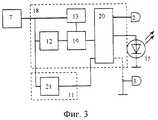
на фиг. 3 - блок-схема другого предпочтительного воплощения предлагаемого электростимулятора, как по первому, так и по второму вариантам.The invention is further illustrated by the drawings, in which
in FIG. 1 is a drawing of the proposed electrical stimulator;
in FIG. 2 is a block diagram of one of the preferred embodiments of the proposed electrostimulator in both the first and second variants;
in FIG. 3 is a block diagram of another preferred embodiment of the proposed electrical stimulator, both in the first and in the second embodiment.
Предлагаемый электростимулятор (фиг. 1) включает втулку 1 из прозрачного материала с напрессованными на нее электродами 2 и 3, образующими корпус устройства, а также установленные внутри указанного корпуса блок 4 излучателей с внешними электрическими контактами и установленными внутри него излучателями (на фиг. 1 не показаны), батареи 5 источника питания и интегральную схему 6. Излучатели в блоке 4 установлены так, что максимум их диаграммы направленности направлен в сторону прозрачного окна, образованного свободной от электродов 2 и 3 поверхностью втулки 1. The proposed electrical stimulator (Fig. 1) includes a
Электрическая схема предлагаемого электростимулятора содержит (фиг. 2, 3) генератор 7 импульсов, подключенные к его выходу формирователи 8, 9 и 10 и блок синхронизации 11, выходы которого подключены к управляющим входам формирователей 8-10. По одному из предпочтительных воплощений (фиг. 2), формирователи пакетов импульсов представляют собой последовательно соединенные счетчик 12, комбинационную схему 13 и логический ключ 14, снабженный двумя управляющими входами, соединенными по функции "логическое И". Один из них используется в качестве управляющего входа формирователя. Вход ключа 14 соединен со счетным входом счетчика 12, и образует вход формирователя, а выход ключа 14 является выходом формирователя. Электрод 2 подключен к выходу формирователя 8, а электрод 3, по первому варианту, подключен к общему проводу, а по второму - к выходу одного из формирователей 8-10, не связанного с электродом 2 (показано пунктиром). Источник излучения 15 может быть подключен к одному из формирователей 8 - 10 (на фиг. 2 - к формирователю 10). Если электрод 2 или 3 подключен к выходу, связанному с источником излучения 15, то подключение производится через токоограничивающий элемент (на схеме не показан). The electrical circuit of the proposed electrical stimulator contains (Fig. 2, 3) a
Блок синхронизации 11 в данном предпочтительном воплощении содержит счетчик 16 и подключенный к его выходу дешифратор 17, выходы которого подключены к управляющим входам формирователей 8 - 10. The synchronization unit 11 in this preferred embodiment comprises a
По другому предпочтительному воплощению (фиг. 3), формирователь пакетов импульсов 18 также представляет собой последовательно соединенные счетчик 12, комбинационную схему 13 и логический ключ 19 с одним управляющим входом. В формирователь 18 дополнительно введен демультиплексор/дешифратор 20, подсоединенный к выходу ключа 18. Адресные входы демультиплексора/дешифратора 20 подключены к старшим, не используемым комбинационной схемой 13, разрядам счетчика 12, которые на фиг. 2 представлены как отдельный счетчик 21, в данном предпочтении выполняющий функцию блока синхронизации 11. Источник излучения 15 может быть подключен к одному из выходов демультиплексора/дешифратора 20. Электрод 2 также подключен к одному из выходов демультиплексора/дешифратора 20. Электрод 3, по первому варианту, подключен к общему проводу, а по второму - к одному из выходов демультиплексора/дешифратора 20, не связанному с электродом 2 (показано пунктиром). Если подключение электрода 2 или 3 производится к выходу, связанному с источником излучения 15, то оно производится через токоограничительный элемент (на схеме не показан). According to another preferred embodiment (Fig. 3), the
Далее приводится описание работы предпочтительных вариантов предлагаемого электростимулятора. Все варианты функционируют одинаково в следующей части. Генератор 7 вырабатывает прямоугольные импульсы, которые поступают на формирователи пакетов импульсов 8 - 10. Комбинационная схема 13 формирует разрешающий сигнал для логического ключа 14 или 19 в заданном диапазоне состояний счетчика 12, и запрещающий сигнал - в остальном диапазоне. Логический ключ 14 (19), во время присутствия разрешающего сигнала на всех управляющих входах одновременно, пропускает на выход формирователя импульсы генератора, формируя таким образом пакеты импульсов и паузы между ними. The following is a description of the preferred embodiments of the proposed electrical stimulator. All options work the same in the next part. The
В первом предпочтительном воплощении, блок синхронизации 11 поочередно разрешает работу формирователей 8 - 10. Разрядность счетчика 16 такова, что состояние его старших разрядов, подключенных к дешифратору 17, изменяется на один после каждого цикла работы формирователей 8 - 10. При этом электрические импульсы подаются на электрод 2 и источник 15 попеременно, если они подключены к разным формирователям, и одновременно - если они подключены к одному формирователю. Нагрузочная способность выхода, к которому подключен электрод 2 (или 3) и подключен источник излучения, должна быть относительно высокой, поэтому если электрод 2 (или 3) и источник 15 подключены к одному формирователю, необходимо последовательно с электродом включить токоограничивающий элемент, например резистор. Необходимость включения токоограничивающего элемента при подключении электрода к отдельному формирователю определяется нагрузочной способностью этого формирователя. По первому варианту, импульсы подаются на электрод 2, а электрод 3 соединен с общим проводом, поэтому полярность импульсов на электродах 2 и 3 не изменяется. Работа второго варианта отличается тем, что импульсы подаются попеременно на электроды 2 и 3, вследствие чего их полярность на электродах 2 и 3 изменяется от пакета к пакету. В данном воплощении, изменяя логические функции комбинационных схем 13 формирователей, можно отдельно управлять параметрами электрических импульсов на электродах 2 и 3 и источнике излучения 15. In the first preferred embodiment, the synchronization unit 11 permits the operation of the shapers 8 - 10 in turn. The digit capacity of the
Во втором предпочтительном воплощении (фиг. 3) на выходе ключа 19 непрерывно формируются пакеты импульсов, которые поочередно подаются на выходы демультиплексора/дешифратора 20, так как разрядность счетчика 21 такова, что его состояние изменяется на 1 после каждого цикла работы формирователя 18. В остальном схема функционирует аналогично описанному выше предпочтительному воплощению, при этом выходы демультиплексора/дешифратора 20 эквивалентны выходам формирователей 8-10. В данном воплощении, параметры пакетов импульсов, поступающих на электроды 2 и 3 и на источник излучения 15 одинаковы, что в большинстве случаев приемлемо и позволяет упростить схему. In the second preferred embodiment (Fig. 3), pulse packets are continuously generated at the output of the key 19, which are alternately supplied to the outputs of the demultiplexer /
Для упрощения схемы, при любом выполнения предлагаемого электростимулятора, в качестве счетчиков 12, 16 или 21 может быть использован один и тот же счетчик, при этом в качестве счетчиков 16 или 21 - старшие разряды этого счетчика. To simplify the scheme, for any implementation of the proposed electrical stimulator, the same counter can be used as
Если необходимо использовать несколько источников излучения (например, с различной длиной волны), их можно подключить к разным формирователям или к одному и тому же. В последнем случае целесообразно соединить источники излучения последовательно. Это упрощает схему, так как при параллельном соединении необходимы токовыравнивающие резисторы. If it is necessary to use several radiation sources (for example, with different wavelengths), they can be connected to different shapers or to the same one. In the latter case, it is advisable to connect the radiation sources in series. This simplifies the circuit, since parallel connection requires current-leveling resistors.
Для осуществления способа описанный выше биологический электростимулятор внутренних органов перорально вводится в ЖКТ. При попадании электростимулятора в кислую среду включается генератор 7 импульсов и на электродах 2 и 3 появляются пакеты электрических импульсов, воздействующие на нервные окончания, находящиеся на стенках кишечника, вследствие чего кишечник расслабляется и капсула продвигается на определенное расстояние. После окончания электрического импульса следующий пакет поступает на источник 15 электромагнитного излучения оптического диапазона, который облучает светом определенной длины волны соответствующий отдел ЖКТ. Терапевтически активная доза, набираемая при прохождении электростимулятором всех отделов ЖКТ, должна быть не менее 1 Дж, а обычно она составляет порядка 10 Дж. To implement the method, the above-described biological electrical stimulator of internal organs is orally administered into the gastrointestinal tract. When the electric stimulator enters the acidic environment, the 7 pulse generator is turned on and packets of electrical pulses appear on the
Пример 1. Больной К. 39 лет. Жалобы на слабость, быструю утомляемость. При инструментальном обследовании патологии не выявлено. Состояние иммунологического статуса: лейкоциты - 4,2 (109/л), лимфоциты - 25%, палочкоядерные нейтрофилы - 2%, сегментоядерные нейтрофилы - 67%. Эозинофилы - 1%, моноциты - 5%, T-лимфоциты - 43%, B-лифоциты - 14%, lgG - 6,8 г/л, lgM - 0,9 г/л, lgA - 1,1 г/л. Заключение: относительная лимфопения, эозинопения, снижение количества T- и B-лимфоцитов, умеренно выраженная гипогаммоглобулинемия. Больному назначена эндогенная фотокоррекция системы иммунитета в режиме стимуляции в дозе 10 Дж. Через пять суток после эндогенной фототерапии субъективное состояние улучшилось. При обследовании системы иммунитета: лейкоциты - 6,7 (109/л), лимфоциты - 35%, палочкоядерные нейтрофилы - 2%, сегментоядерные нейтрофилы - 54%. Эозинофилы - 3%, моноциты - 6%, T-лимфоциты - 61%, B-лифоциты - 12%, lgG - 12,8 г/л, lgM - 1,4 г/л, lgA - 1,7 г/л. Заключение: иммунологический статус без патологических изменений.Example 1. Patient K., 39 years old. Complaints of weakness, fatigue. An instrumental examination revealed no pathology. The state of immunological status: leukocytes - 4.2 (109 / L), lymphocytes - 25%, stab neutrophils - 2%, segmented neutrophils - 67%. Eosinophils - 1%, monocytes - 5%, T-lymphocytes - 43%, B-lymphocytes - 14%, logG - 6.8 g / l, logM - 0.9 g / l, logA - 1.1 g / l . Conclusion: relative lymphopenia, eosinopenia, a decrease in the number of T- and B-lymphocytes, moderate hypogammoglobulinemia. The patient was prescribed endogenous photocorrection of the immune system in a stimulation mode at a dose of 10 J. Five days after endogenous phototherapy, the subjective state improved. When examining the immune system: leukocytes - 6.7 (109 / l), lymphocytes - 35%, stab neutrophils - 2%, segmented neutrophils - 54%. Eosinophils - 3%, monocytes - 6%, T-lymphocytes - 61%, B-lymphocytes - 12%, logG - 12.8 g / l, logM - 1.4 g / l, logA - 1.7 g / l . Conclusion: immunological status without pathological changes.
Пример 2. Больной И. 43 лет. Жалобы на периодические боли в эпигастральной области, нарушение сна. При фиброгастродуоденоскопии - поверхностный гастрит. Секреторная и кислотообразующая функции не изменены. Состояние иммунологического статуса: лейкоциты - 8,2 (109/л), лимфоциты - 43%, палочкоядерные нейтрофилы - 1%, сегментоядерные нейтрофилы - 48%. Эозинофилы - 5%, моноциты - 3%, T-лимфоциты -69%, B-лифоциты - 22%, lgG - 15,1 г/л, lgM - 1,7 г/л, lgA - 0,9 г/л. Заключение: относительная эозинофилия, повышение количества T- и B-лимфоцитов, умеренно выраженная дисгаммоглобулинемия (незначительное повышение уровня иммуноглобулинов G и М). Больному назначена эндогенная фотокоррекция системы иммунитета в режиме ингибирования в дозе 20 Дж. Через пять суток после эндогенной фототерапии субъективное состояние улучшилось. При обследовании системы иммунитета: лейкоциты - 5,7 (109/л), лимфоциты - 33%, палочкоядерные нейтрофилы - 1%, сегментоядерные нейтрофилы - 58%. Эозинофилы - 3%, моноциты - 5%, T-лимфоциты - 63%, B-лифоциты - 15%, lgG -10,7 г/л, lgM - 1,2 г/л, lgA - 1,3 г/л. Заключение: иммунологический статус без патологических изменений.Example 2. Patient I., 43 years old. Complaints of recurrent epigastric pain, sleep disturbance. With fibrogastroduodenoscopy - superficial gastritis. Secretory and acid-forming functions are not changed. The status of the immunological status: leukocytes - 8.2 (109 / l), lymphocytes - 43%, stab neutrophils - 1%, segmented neutrophils - 48%. Eosinophils - 5%, monocytes - 3%, T-lymphocytes - 69%, B-lymphocytes - 22%, logG - 15.1 g / l, logM - 1.7 g / l, logA - 0.9 g / l . Conclusion: relative eosinophilia, an increase in the number of T- and B-lymphocytes, moderate dysammoglobulinemia (a slight increase in the level of immunoglobulins G and M). The patient was prescribed endogenous photocorrection of the immune system in the inhibition mode at a dose of 20 J. Five days after endogenous phototherapy, the subjective state improved. When examining the immune system: leukocytes - 5.7 (109 / l), lymphocytes - 33%, stab neutrophils - 1%, segmented neutrophils - 58%. Eosinophils - 3%, monocytes - 5%, T-lymphocytes - 63%, B-lymphocytes - 15%, logG - 10.7 g / l, logM - 1.2 g / l, lgA - 1.3 g / l . Conclusion: immunological status without pathological changes.
Пример 3. Больной Г. 36 лет. Example 3. Patient G. 36 years.
Состояние удовлетворительное, жалобы на периодические боли в животе, после приема острой пищи стул жидкий со слизью и примесью крови. Болен в течение 5 лет. При исследовании кала на микрофлору обнаружено: патогенных микробов семейства кишечных - 0, кишечная палочка со слабо выраженными ферментативными свойствами, % - 2, лактозонегативные энтеробактерии, % - 15, гемолизирующая кишечная палочка, % - 0, кокковые формы в общей сумме микробов, % - 20, гемолизирующий стафиллококк, по отношению ко всем кокковым формам, % - 0, бифидобактерии - 104 лактобактерии - 103, микробы рода протея - 0. Снижение числа колоний кишечной палочки, бифидобактерии, лактобактерии.The condition is satisfactory, complaints of recurrent abdominal pain, after eating spicy foods, the stool is liquid with mucus and an admixture of blood. Sick for 5 years. When examining feces on the microflora, it was found: pathogenic microbes of the intestinal family - 0, E. coli with weakly expressed enzymatic properties,% - 2, lactose-negative enterobacteria,% - 15, hemolysing E. coli,% - 0, coccal forms in the total amount of microbes,% - 20, hemolysing staphillococcus, in relation to all coccal forms,% - 0, bifidobacteria - 104 lactobacilli - 103 , microbes of the genus Proteus - 0. Decrease in the number of colonies of Escherichia coli, bifidobacteria, lactobacilli.
Диагноз: хронический неспецифический колит, хроническая форма, легкое течение, дисбактериоз II ст. Diagnosis: chronic nonspecific colitis, chronic form, mild course, dysbiosis II tbsp.
Назначено лечение - эндогенная фототерапия с использованием предлагаемого электростимулятора, с облучением синим светом. После проведенного лечения состояние больного улучшилось, боли уменьшились, слизи и крови в кале не определяется. При исследовании кала на микрофлору обнаружено: патогенных микробов семейства кишечных - 0, кишечная палочка со слабо выраженными ферментативными свойствами, % - 10, лактозонегативные энтеробактерии, % - 5, гемолизирующая кишечная палочка, % - 0, кокковые формы в общей сумме микробов, % - 20, гемолизирующий стафиллококк, по отношению ко всем кокковым формам, % - 0, бифидобактерии - 107, лактобактерии - 104, микробы рода протея - 0. Заключение: возросло число колоний кишечной палочки, бифидобактерий, лактобактерий. Через два месяца состояние больного удовлетворительное, бактериологический анализ кала без отрицательной динамики.The treatment was prescribed - endogenous phototherapy using the proposed electrical stimulator, with exposure to blue light. After the treatment, the patient's condition improved, the pain decreased, mucus and blood in the feces is not determined. In the study of feces on the microflora, it was found that: pathogenic microbes of the intestinal family — 0, E. coli with weakly expressed enzymatic properties,% - 10, lactose-negative enterobacteria,% - 5, hemolysing E. coli,% - 0, coccal forms in the total amount of microbes,% - 20, hemolysing staphillococcus, with respect to all coccal forms,% - 0, bifidobacteria - 107 , lactobacilli - 104 , microbes of the genus Proteus - 0. Conclusion: the number of colonies of Escherichia coli, bifidobacteria, lactobacilli has increased. Two months later, the patient's condition is satisfactory, bacteriological analysis of feces without negative dynamics.
Диагноз: хронический неспецифический колит, стадия стойкой ремиссии. Diagnosis: chronic nonspecific colitis, stage of stable remission.
На основании вышеизложенных примеров подтверждена высокая эффективность лечения с одновременным использованием светового облучения и электрической стимуляции всех отделов ЖКТ. Based on the above examples, the high efficiency of treatment with the simultaneous use of light irradiation and electrical stimulation of all sections of the gastrointestinal tract was confirmed.
Источники информации, использованные при составлении описания
1. Патент РФ N 2108122 6 МПК: A 61 M 5/06 опубл. БИ N 10 10.04.98.Sources of information used in compiling the description
1. RF patent N 2108122 6 IPC: A 61 M 5/06 publ. BI 10.04.04.88.
2. Патент РФ N 2071368 6 МПК: A 61 N 1/375 опубл. БИ N 1 10.01.97
3. Патент РФ N 2081636 6 МПК: A 61 N 1/36 опубл. БИ N 17 20.06.97
4. Патент РФ N 2089239 6 МПК: A 61 N 1/36 опубл. БИ N 25 10.09.97.2. RF patent N 2071368 6 IPC: A 61
3. RF patent N 2081636 6 IPC: A 61
4. RF patent N 2089239 6 IPC: A 61
5. Кару Т. И. Фотобиология низкоинтенсивной лазеротерапии. // Итоги науки и техники. Физические основы лазерной и пучковой технологии. М.: Наука, 1989, с. 69-72. 5. Karu T. I. Photobiology of low-intensity laser therapy. // Results of science and technology. Physical fundamentals of laser and beam technology. M .: Nauka, 1989, p. 69-72.
Claims (22)
Translated fromRussianPriority Applications (1)
| Application Number | Priority Date | Filing Date | Title |
|---|---|---|---|
| RU98119500ARU2145892C1 (en) | 1998-10-26 | 1998-10-26 | Method and biological organ electrostimulation means for correcting functional state of immune system organs |
Applications Claiming Priority (1)
| Application Number | Priority Date | Filing Date | Title |
|---|---|---|---|
| RU98119500ARU2145892C1 (en) | 1998-10-26 | 1998-10-26 | Method and biological organ electrostimulation means for correcting functional state of immune system organs |
Publications (1)
| Publication Number | Publication Date |
|---|---|
| RU2145892C1true RU2145892C1 (en) | 2000-02-27 |
Family
ID=20211709
Family Applications (1)
| Application Number | Title | Priority Date | Filing Date |
|---|---|---|---|
| RU98119500ARU2145892C1 (en) | 1998-10-26 | 1998-10-26 | Method and biological organ electrostimulation means for correcting functional state of immune system organs |
Country Status (1)
| Country | Link |
|---|---|
| RU (1) | RU2145892C1 (en) |
Cited By (3)
| Publication number | Priority date | Publication date | Assignee | Title |
|---|---|---|---|---|
| RU2182499C2 (en)* | 2000-07-26 | 2002-05-20 | Гусев Владимир Васильевич | Method for rendering human organism healthy |
| RU2289447C2 (en)* | 2003-09-26 | 2006-12-20 | Институт сильноточной электроники СО РАН | Method and active electrophotostimulator device for restoring gastrointestinal tract trophism |
| RU2291721C1 (en)* | 2005-08-30 | 2007-01-20 | Государственное научное учреждение Научно-исследовательский ветеринарный институт Нечерноземной зоны РФ Российской академии сельскохозяйственных наук | Method for correcting immunodeficiency in neonatal calves |
Citations (11)
| Publication number | Priority date | Publication date | Assignee | Title |
|---|---|---|---|---|
| EP0320080A1 (en)* | 1987-11-13 | 1989-06-14 | Omega Universal Limited | Device for biostimulation of tissue |
| WO1991012050A1 (en)* | 1990-02-09 | 1991-08-22 | Omega Universal Holdings Limited | Probe, and method of use thereof for biomudulation of tissue, nerve and immune systems |
| DE4015406A1 (en)* | 1990-05-14 | 1991-11-28 | Munz Marianne Dipl Ing Fh | Heat and light therapy procedure - radiating selection of coloured polarised light for treatment of skin ailments and bodily functions |
| EP0571938A2 (en)* | 1992-05-29 | 1993-12-01 | Valerio Cigaina | Process and device for treating obesity and motor disorders of the stomach |
| RU2066554C1 (en)* | 1996-01-18 | 1996-09-20 | Акционерное общество открытого типа "Завод "Компонент" | Gastroenteric tract electrostimulator |
| RU2075980C1 (en)* | 1996-01-18 | 1997-03-27 | Акционерное общество открытого типа "Завод "Компонент" | Electrostimulator of gastrointestinal tract |
| RU2081636C1 (en)* | 1996-06-25 | 1997-06-20 | Сергей Александрович Хворостов | Method to correct immunity parameters |
| WO1997031679A2 (en)* | 1996-02-27 | 1997-09-04 | Vladimir Nikolaevich Dirin | Biological electrostimulator of viscera |
| WO1997036646A1 (en)* | 1996-04-01 | 1997-10-09 | Valery Ivanovich Kobozev | Electrical gastro-intestinal tract stimulator |
| RU2094068C1 (en)* | 1997-03-27 | 1997-10-27 | Закрытое акционерное общество "ЯНИНВЕСТ" | Method of nose disease treatment and device intended for its realization |
| RU2104722C1 (en)* | 1994-07-04 | 1998-02-20 | Новокузнецкий государственный институт усовершенствования врачей | Metod for treating infantile distal colitis |
- 1998
- 1998-10-26RURU98119500Apatent/RU2145892C1/enactive
Patent Citations (11)
| Publication number | Priority date | Publication date | Assignee | Title |
|---|---|---|---|---|
| EP0320080A1 (en)* | 1987-11-13 | 1989-06-14 | Omega Universal Limited | Device for biostimulation of tissue |
| WO1991012050A1 (en)* | 1990-02-09 | 1991-08-22 | Omega Universal Holdings Limited | Probe, and method of use thereof for biomudulation of tissue, nerve and immune systems |
| DE4015406A1 (en)* | 1990-05-14 | 1991-11-28 | Munz Marianne Dipl Ing Fh | Heat and light therapy procedure - radiating selection of coloured polarised light for treatment of skin ailments and bodily functions |
| EP0571938A2 (en)* | 1992-05-29 | 1993-12-01 | Valerio Cigaina | Process and device for treating obesity and motor disorders of the stomach |
| RU2104722C1 (en)* | 1994-07-04 | 1998-02-20 | Новокузнецкий государственный институт усовершенствования врачей | Metod for treating infantile distal colitis |
| RU2066554C1 (en)* | 1996-01-18 | 1996-09-20 | Акционерное общество открытого типа "Завод "Компонент" | Gastroenteric tract electrostimulator |
| RU2075980C1 (en)* | 1996-01-18 | 1997-03-27 | Акционерное общество открытого типа "Завод "Компонент" | Electrostimulator of gastrointestinal tract |
| WO1997031679A2 (en)* | 1996-02-27 | 1997-09-04 | Vladimir Nikolaevich Dirin | Biological electrostimulator of viscera |
| WO1997036646A1 (en)* | 1996-04-01 | 1997-10-09 | Valery Ivanovich Kobozev | Electrical gastro-intestinal tract stimulator |
| RU2081636C1 (en)* | 1996-06-25 | 1997-06-20 | Сергей Александрович Хворостов | Method to correct immunity parameters |
| RU2094068C1 (en)* | 1997-03-27 | 1997-10-27 | Закрытое акционерное общество "ЯНИНВЕСТ" | Method of nose disease treatment and device intended for its realization |
Cited By (3)
| Publication number | Priority date | Publication date | Assignee | Title |
|---|---|---|---|---|
| RU2182499C2 (en)* | 2000-07-26 | 2002-05-20 | Гусев Владимир Васильевич | Method for rendering human organism healthy |
| RU2289447C2 (en)* | 2003-09-26 | 2006-12-20 | Институт сильноточной электроники СО РАН | Method and active electrophotostimulator device for restoring gastrointestinal tract trophism |
| RU2291721C1 (en)* | 2005-08-30 | 2007-01-20 | Государственное научное учреждение Научно-исследовательский ветеринарный институт Нечерноземной зоны РФ Российской академии сельскохозяйственных наук | Method for correcting immunodeficiency in neonatal calves |
Similar Documents
| Publication | Publication Date | Title |
|---|---|---|
| TWI306407B (en) | Apparatus and method for generating an electrical signal for use in biomedical applications | |
| RU2075980C1 (en) | Electrostimulator of gastrointestinal tract | |
| US8088057B2 (en) | Apparatus and methods to improve sleep, reduce pain and promote natural healing | |
| Hakimiha et al. | Recovery of inferior alveolar nerve by photobiomodulation therapy using two laser wavelengths: A behavioral and immunological study in rat | |
| EP3737464A1 (en) | Methods and systems for stimulation for glial modulation | |
| WO2005096930A2 (en) | Method and apparatus for treating the body | |
| US6913616B2 (en) | Laser ionization therapy system and method | |
| Shimizu et al. | Effect of electrical stimulation of the infralimbic and prelimbic cortices on anxiolytic-like behavior of rats during the elevated plus-maze test, with particular reference to multiunit recording of the behavior-associated neural activity | |
| RU2145892C1 (en) | Method and biological organ electrostimulation means for correcting functional state of immune system organs | |
| US20050209656A1 (en) | Method and apparatus for applying microcurrent to eyes | |
| Nair et al. | Mitigation of cancer therapy side-effects with light | |
| RU2222311C2 (en) | Apparatus for treating diseases by electrically acting upon biologically active points according to "boo- sho" rules | |
| RU155525U1 (en) | DEVICE FOR THERAPEUTIC INFLUENCE OF ELECTROMAGNETIC VIBRATIONS OF THE OPTICAL RANGE | |
| RU2289447C2 (en) | Method and active electrophotostimulator device for restoring gastrointestinal tract trophism | |
| Humphris | Artificial sunlight and its therapeutic uses | |
| Bischof | The history of bioelectromagnetism | |
| RU2112564C1 (en) | Method for correction of bioenergetic area - functional state of cells and device for its realization | |
| RU9741U1 (en) | GASTROINTESTINAL STIMULATOR | |
| RU2257195C1 (en) | Method of influencing on biologically active points during procedure of reflexotherapy at thyroid gland dysfunction | |
| RU202855U1 (en) | DEVICE FOR ELECTRONIC STIMULATION | |
| RU2001118151A (en) | METHOD AND DEVICES FOR ADJUSTING ORGANISM BIORITHMS BY ELECTRICAL INFLUENCE UNDER THE "BU-SE" REGULATIONS | |
| RU51505U1 (en) | DEVICE FOR TRANSMISSION ELECTRON NEURO-STIMULATION | |
| RU2113865C1 (en) | Electrostimulation device | |
| RU2134128C1 (en) | Stimulator of gastroenteric tract | |
| KR910002094B1 (en) | Dental Laser Generating Circuit |