RU2145423C1 - Method determining coordinates of mobile objects - Google Patents
Method determining coordinates of mobile objectsDownload PDFInfo
- Publication number
- RU2145423C1 RU2145423C1RU97114591/09ARU97114591ARU2145423C1RU 2145423 C1RU2145423 C1RU 2145423C1RU 97114591/09 ARU97114591/09 ARU 97114591/09ARU 97114591 ARU97114591 ARU 97114591ARU 2145423 C1RU2145423 C1RU 2145423C1
- Authority
- RU
- Russia
- Prior art keywords
- coordinates
- coordinate system
- xzi
- xyi
- zxi
- Prior art date
Links
- 238000000034methodMethods0.000titleclaimsabstractdescription18
- 238000012937correctionMethods0.000claimsabstractdescription14
- 238000006243chemical reactionMethods0.000claimsdescription13
- 238000005259measurementMethods0.000claimsdescription9
- 239000000126substanceSubstances0.000abstract1
- 230000000875corresponding effectEffects0.000description10
- 230000009897systematic effectEffects0.000description6
- 230000015572biosynthetic processEffects0.000description4
- 238000012545processingMethods0.000description4
- 238000004364calculation methodMethods0.000description2
- -1atmosphericSubstances0.000description1
- 230000005540biological transmissionEffects0.000description1
- 238000010276constructionMethods0.000description1
- 230000002596correlated effectEffects0.000description1
- 230000001934delayEffects0.000description1
- 238000013461designMethods0.000description1
- 238000010586diagramMethods0.000description1
- 238000000605extractionMethods0.000description1
- 239000005433ionosphereSubstances0.000description1
- 230000003137locomotive effectEffects0.000description1
- 239000011159matrix materialSubstances0.000description1
- 238000001228spectrumMethods0.000description1
- 230000009466transformationEffects0.000description1
Images
Landscapes
- Position Fixing By Use Of Radio Waves (AREA)
Abstract
Description
Translated fromRussianПредлагаемое изобретение относится к навигации и может быть использовано для определения координат подвижных объектов, движущихся по известному маршруту, например железнодорожных поездов с высокой точностью. The present invention relates to navigation and can be used to determine the coordinates of moving objects moving along a known route, for example, railway trains with high accuracy.
Известен способ определения координат подвижных объектов, основанный на приеме сигналов космических аппаратов глобальных навигационных спутниковых систем, измерении псевдодальностей от навигационных космических аппаратов и определении координат подвижного объекта по измеренным псевдодальностям. [Радиотехнические системы/ Ю.П.Гришин, В.П.Ипатов, Ю.М.Казаринов и др. - М. Высш.шк., 1990, 496 с., стр. 302]. A known method for determining the coordinates of moving objects, based on the reception of signals from spacecraft global navigation satellite systems, measuring pseudorange from navigation spacecraft and determining the coordinates of a moving object from the measured pseudorange. [Radio engineering systems / Yu.P. Grishin, V. P. Ipatov, Yu. M. Kazarinov et al. - M. Higher school, 1990, 496 p., P. 302].
Этот способ обеспечивает определение местоположения подвижных объектов в любое время и в любой точке Земного шара. Погрешность определения координат этим способом составляет порядка 50 - 150 метров. This method provides the location of moving objects at any time and anywhere in the world. The error in determining the coordinates in this way is about 50 - 150 meters.
Недостатком способа является недостаточно высокая точность определения местоположения подвижного объекта. В ряде случаев требуется обеспечение погрешности 3-10 метров. The disadvantage of this method is the insufficiently high accuracy of determining the location of a moving object. In some cases, an error of 3-10 meters is required.
Известен способ определения координат объектов, взятый в качестве прототипа, основанный на приеме на подвижном объекте и контрольно-корректирующей станции с известными координатами сигналов космических аппаратов глобальных навигационных спутниковых систем, измерении на подвижном объекте и контрольно-корректирующей станции псевдодальностей от соответствующих навигационных космических аппаратов, определении поправок к измеряемым псевдодальностям по разности между измеренными и истинными дальностями, передаче поправок с контрольно-корректирующей станции на подвижный объект и определении координат подвижного объекта по измеренным на подвижном объекте псевдодальностям с учетом поправок, переданных с контрольно-корректирующей станции [B.С. Шебшаевич, П. П. Дмитриев, Н.В. Иванцевич и др.; Под ред. B.С. Шебшаевича. - 2-е изд. , перераб. и доп. - М.: Радио и связь, 1993. - 408 с.: ил. - ISBN 5-256-00174-4, стр. 282]. A known method for determining the coordinates of objects, taken as a prototype, based on reception on a moving object and a control and correction station with known coordinates of signals from spacecraft global navigation satellite systems, measuring on a moving object and a control and correction station pseudorange from the corresponding navigation spacecraft, determining corrections to measured pseudo-ranges according to the difference between measured and true ranges, transmission of corrections to control o-correcting station on the movable object and determining coordinates of the mobile object measured at the mobile unit pseudorange amended transmitted from the control and correction station [VS Shebshaevich, P.P. Dmitriev, N.V. Ivantsevich et al .; Ed. B.S. Shebshaevich. - 2nd ed. , reslave. and add. - M .: Radio and communications, 1993 .-- 408 p.: Ill. - ISBN 5-256-00174-4, p. 282].
Недостатком этого способа является повышенная сложность его реализации, связанная с необходимостью установки специальной аппаратуры в фиксированной точке с известными координатами и передачи поправок на подвижный объект, что может быть осуществлено только при помощи радиоканала. The disadvantage of this method is the increased complexity of its implementation, associated with the need to install special equipment at a fixed point with known coordinates and transmit corrections to a moving object, which can only be done using a radio channel.
Как видно из анализа рассмотренных способов, они имеют ряд недостатков, не позволяющих обеспечить высокоточное определение координат без существенного аппаратурного усложнения при их реализации. As can be seen from the analysis of the considered methods, they have a number of disadvantages that do not allow for highly accurate determination of coordinates without significant hardware complication in their implementation.
В основу изобретения положена задача повышения точности определения координат подвижных объектов практически без усложнения аппаратуры, реализующей способ, путем использования априорных сведений, связанных с движением объекта по известному маршруту, например по железной дороге. The basis of the invention is the task of increasing the accuracy of determining the coordinates of moving objects practically without complicating the equipment that implements the method by using a priori information related to the movement of the object along a known route, for example by rail.
Поставленная задача достигается тем, что в способе определения местоположения подвижных объектов, основанном на приеме сигналов космических аппаратов глобальных навигационных спутниковых систем, измерении псевдодальностей, введении поправок и вычислении координат объекта, согласно изобретению проводят n измерений псевдодальностей и вычислений координат объекта, движущегося по известному маршруту, например по железной дороге, определяют точки xi0, yi0, zi0, лежащие на известном маршруте и соответствующие кратчайшему расстоянию до точек с измеренными координатами xi *, yi *, zi *, и определяют поправки путем решения системы из 3n уравнений:
где i = 1, n;
axxi, axyi, axzi, ayxi, ayyi, ayzi, azxi, azyi, azzi - коэффициенты пересчета координат из специальной топоцентрической системы координат с центром в точке xi0, yi0, zi0, осями Xтi и Yтi, лежащими в горизонтальной плоскости и осью Zтi, направленной вертикально вверх, причем точка xi, yi, zi лежит в плоскости (Xтi, Zтi), а касательная к известному маршруту лежит в плоскости (Yтi, Zтi), в геоцентрическую систему координат:
Δxi = bxxi(xi * - xi0) + bxyi(yi * - yi0) + bxzi(zi *- zi0),
Δzi = bzxi(xi * - xi0) + bzyi(yi * - yi0) + bzzi(zi *- zi0);
bxxi, bxyi, bxzi, bzxi, bzyz, bzxzi - коэффициенты пересчета координат из геоцентрической системы координат в специальную топоцентрическую систему координат с указанными характеристиками;
Δyi - n сопутствующих неизвестных,
Δx, Δy, Δz - определяемые поправки.The problem is achieved in that in the method for determining the location of moving objects, based on the reception of signals from spacecraft of global navigation satellite systems, measuring pseudorange, introducing corrections and calculating the coordinates of the object, according to the invention, n measurements of pseudorange and calculation of the coordinates of an object moving along a known route are carried out, for example, by rail, determine the points xi0 , yi0 , zi0 lying on a known route and corresponding to the shortest distance to ek with the measured coordinates xi* , yi* , zi* , and determine the corrections by solving a system of 3n equations:
where i = 1, n;
axxi , axyi , axzi , ayxi , ayyi , ayzi , azxi , azyi , azzi - conversion factors from a special topocentric coordinate system centered at the point xi0 , yi0 , zi0 , X axesti and Yti lying in the horizontal plane and the Zti axis directed vertically upward, and the point xi , yi , zi lies in the plane (Xti , Zti ), and the tangent to the known route lies in the plane (Yti , Zti ), into the geocentric coordinate system:
Δxi = bxxi (xi* - xi0 ) + bxyi (yi* - yi0 ) + bxzi (zi* - zi0 ),
Δzi = bzxi (xi* - xi0 ) + bzyi (yi* - yi0 ) + bzzi (zi* - zi0 );
bxxi , bxyi , bxzi , bzxi , bzyz , bzxzi - conversion factors of coordinates from the geocentric coordinate system to a special topocentric coordinate system with the specified characteristics;
Δyi - n related unknowns,
Δx, Δy, Δz - defined amendments.
Сущность предлагаемого способа заключается в следующем. The essence of the proposed method is as follows.
Измерение координат при помощи глобальных навигационных спутниковых систем производится путем измерения псевдодальностей Ri от точки, в которой находится объект, до точки нахождения навигационных космических аппаратов. Первичное определение координат производится в так называемой геоцентрической системе координат с центром, находящимся в центре Земли. Coordinates are measured using global navigation satellite systems by measuring the pseudorange Ri from the point at which the object is located to the location of the navigation spacecraft. The primary determination of the coordinates is carried out in the so-called geocentric coordinate system with the center located in the center of the Earth.
При определении координат при помощи глобальных навигационных спутниковых систем возникают систематические погрешности, связанные с эфемеридной, ионосферной, атмосферной и др. составляющими. Это так называемые сильно коррелированные составляющие погрешности, которые медленно изменяются во времени и пространстве. Благодаря этому их свойству, систематические погрешности при определенных условиях можно уменьшить или исключить. Местоположение объекта, координаты которого измеряются, находится на известном маршруте движения, например, как это происходит на железной дороге или автомобильной трассе. При движении объекта по известному маршруту первичные координаты, измеренные традиционным способом, будут находиться вследствие погрешности не на линии маршрута, а в стороне от него. Поскольку уравнение маршрута известно, можно определить точку xi0, yi0, zi0, лежащую на маршруте и соответствующую кратчайшему расстоянию от точки с измеренными координатами до линии маршрута.When determining coordinates using global navigation satellite systems, systematic errors arise associated with the ephemeris, ionosphere, atmospheric, and other components. These are the so-called highly correlated error components that slowly change in time and space. Due to their property, systematic errors under certain conditions can be reduced or eliminated. The location of the object whose coordinates are measured is located on a known route, for example, as it happens on a railway or highway. When an object moves along a known route, the primary coordinates measured in the traditional way will be due to an error not on the route line, but on the side of it. Since the route equation is known, it is possible to determine the point xi0 , yi0 , zi0 lying on the route and corresponding to the shortest distance from the point with measured coordinates to the route line.
Обозначим координаты точки истинного положения объекта на маршруте через xi, yi, zi, а измеренные координаты через xi *, yi *, zi *.We denote the coordinates of the point of the true position of the object along the route by xi , yi , zi , and the measured coordinates by xi* , yi* , zi* .
Систематические погрешности определения координат в геоцентрической системе, которые обозначим через Δx, Δy, Δz, не зависят от номера измерения, то есть от местоположения объекта. The systematic errors in determining the coordinates in the geocentric system, which we denote by Δx, Δy, Δz, do not depend on the measurement number, i.e., on the location of the object.
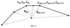
Введем специальную топоцентрическую систему координат с центром в точке xi0, yi0, zi0, осями Xтi и Yтi, лежащими в горизонтальной плоскости, и осью Zтi, направленной вертикально вверх, причем точка лежит в плоскости (Xтi, Zтi), а касательная к известному маршруту лежит в плоскости (Yтi, Zтi) (см. фиг.1). Обозначим координаты истинного положения объекта в специальной топоцентрической системе координат через xTi, yTi, zTi, а измеренные координаты через xTi *, yTi *, zTi *.We introduce a special topocentric coordinate system centered at the point xi0 , yi0 , zi0 , the axes Xti and Yti lying in the horizontal plane, and the axis Zti directed vertically upward, and the point lies in the plane (Xti , Zti ), and the tangent to the known route lies in the plane (YTi , ZTi ) (seefigure 1). We denote the coordinates of the true position of the object in a special topocentric coordinate system by xTi , yTi , zTi , and the measured coordinates by xTi* , yTi* , zTi* .
В специальной топоцентрической системе координат, т.е. по осям Xтi, Yтi, Zтi, погрешности первичного определения координат соответствуют Δxi, Δyi, Δzi. Истинное местоположение объекта в специальной топоцентрической системе координат находится на оси Yтi и имеет следующие координаты: xTi = 0, yTi = Δ yi, zTi = 0. Измеренные координаты в специальной топоцентрической системе координат равны
x
Эти координаты связаны с их значениями в геоцентрической системе координат следующими линейными соотношениями:
xTi * = bxxi(xi * - xi0) + bxyi(yi * - yi0) + bxzi(zi * - zi0),
yTi * = 0
zTi * = bzxi(xi * - xi0) + bzyi(yi * - yi0) + bzzi(zi * - zi0), (2)
где bxxi, bxyi, bxzi, bzxi, bzyz, bzxzi - коэффициенты пересчета координат из геоцентрической системы координат в специальную топоцентрическую систему координат с указанными характеристиками.In a special topocentric coordinate system, i.e. along the axes Xti , Yti , Zti , the errors of the initial determination of the coordinates correspond to Δxi , Δyi , Δzi . The true location of the object in a special topocentric coordinate system is located on the Y axisti and has the following coordinates: xTi = 0, yTi = Δ yi , zTi = 0. The measured coordinates in the special topocentric coordinate system are
x
These coordinates are related to their values in the geocentric coordinate system by the following linear relationships:
xTi* = bxxi (xi* - xi0 ) + bxyi (yi* - yi0 ) + bxzi (zi* - zi0 ),
yTi* = 0
zTi* = bzxi (xi* - xi0 ) + bzyi (yi* - yi0 ) + bzzi (zi* - zi0 ), (2)
where bxxi , bxyi , bxzi , bzxi , bzyz , bzxzi are the coefficients for converting coordinates from the geocentric coordinate system to a special topocentric coordinate system with the specified characteristics.
Как видно из (1, 2), систематические погрешности в специальной топоцентрической системе координат по осям Xтi, Zтi равны значениям измеренных координат по этим осям. As can be seen from (1, 2), systematic errors in a special topocentric coordinate system along the axes Xti, Zti are equal to the values of the measured coordinates along these axes.
Учитывая, что параметры специальной топоцентрической системы координат известны, определение коэффициентов пересчета осуществляют по известным правилам преобразования координат из одной системы координат в другую. Систематические погрешности Δx, Δy, Δz в геоцентрической системе координат связаны с систематическими погрешностями в специальной топоцентрической системе координат Δxi, Δyi, Δzi следующими линейными соотношениями:
где i = 1, n
axxi, axyi, axzi, ayxi, ayyi, ayzi, azxi, azyi, azzi- (4)
коэффициенты пересчета координат из специальной топоцентрической системы координат в геоцентрическую систему координат,
Система (3) содержит 3n уравнений и 3+n(Δx, Δy, Δz и Δyi) неизвестных и решается методом наименьших квадратов. Например, при n = 2 система преобразуется к следующему виду (в матричной форме):
где:
На фиг. 1 приведена специальная топоцентрическая система координат, на которой приведены точки, соответствующие измеренным и истинным координатам; на фиг. 2 приведена структурная схема устройства, реализующего предложенный способ, на фиг. 3 приведен график, аппроксимирующий маршрут движения объекта отрезками прямых.Given that the parameters of the special topocentric coordinate system are known, the determination of conversion factors is carried out according to the known rules for the transformation of coordinates from one coordinate system to another. The systematic errors Δx, Δy, Δz in the geocentric coordinate system are associated with systematic errors in the special topocentric coordinate system Δxi , Δyi , Δzi with the following linear relationships:
where i = 1, n
axxi , axyi , axzi , ayxi , ayyi , ayzi , azxi , azyi , azzi - (4)
conversion factors for coordinates from a special topocentric coordinate system to a geocentric coordinate system,
System (3) contains 3n equations and 3 + n (Δx, Δy, Δz and Δyi ) unknowns and is solved by the least squares method. For example, with n = 2, the system is transformed to the following form (in matrix form):
Where:
In FIG. 1 shows a special topocentric coordinate system, which shows the points corresponding to the measured and true coordinates; in FIG. 2 shows a structural diagram of a device that implements the proposed method, FIG. Figure 3 shows a graph approximating the route of movement of an object by line segments.
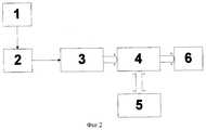
Устройство содержит последовательно включенные антенну 1, радиотракт 2, блок цифровой обработки 3, микропроцессорный блок 4, блок базы данных 5, а также индикатор 6, подключенный к микропроцессорному блоку 4. The device contains a series-connected
Предлагаемый способ реализуется следующим образом. Сигналы от космических аппаратов глобальных навигационных спутниковых систем принимаются антенной 1 и поступают в радиотракт 2. Радиотракт 2 осуществляет усиление, фильтрацию и перенос спектра принимаемых сигналов на промежуточную частоту. Далее сигнал промежуточной частоты преобразуется в цифровую форму. Обработка цифрового сигнала производится многоканальным блоком 3 цифровой обработки сигналов. The proposed method is implemented as follows. The signals from the spacecraft of the global navigation satellite systems are received by
Блок цифровой обработки сигналов выполняет следующие функции:
- формирование квадратурных опорных сигналов перестраиваемых по частоте и фазе в соответствии с принимаемыми сигналами навигационных космических аппаратов, например ГЛОНАСС и GPS;
- формирование опорных сигналов псевдослучайных последовательностей (ПСП) навигационных космических аппаратов, перестраиваемых по задержке;
- перемножение входного сигнала на опорные сигналы литерной частоты и ПСП;
- формирование отсчетов корреляционных интегралов на интервале измерения.The digital signal processing unit performs the following functions:
- the formation of quadrature reference signals tunable in frequency and phase in accordance with the received signals of navigation spacecraft, such as GLONASS and GPS;
- the formation of reference signals of pseudo-random sequences (PSP) of navigation spacecraft, tunable delay;
- multiplication of the input signal by the reference signals of the letter frequency and the SRP;
- formation of samples of correlation integrals on the measurement interval.
Накопленные на интервале измерения значения корреляционных интегралов передаются по шине в микропроцессорный вычислительный блок 4. The values of the correlation integrals accumulated over the measurement interval are transmitted via the bus to the
Микропроцессорный вычислительный блок 4 выполняет следующие функции:
поиск сигнала по задержке и доплеровскому сдвигу частоты;
- слежение за сигналом по задержке и фазе;
- измерение радионавигационных параметров сигнала (задержки распространения и доплеровского сдвига частоты);
- демодуляцию цифровой информации, поступающей с навигационных космических аппаратов;
- декодирование цифровой информации, принятой с навигационных космических аппаратов, и расчет их координат на текущее время;
- по результатам измерения задержки сигналов и координатам навигационных космических аппаратов вычисление координат подвижного объекта xi *, yi *, zi *; - определение точки xi0, yi0, zi0, лежащей на маршруте и соответствующей кратчайшему расстоянию до точки с измеренными координатами xi *, yi *, zi *;
- определение коэффициентов пересчета координат из специальной топоцентрической системы координат в геоцентрическую систему координат axxi, axyi, axzi, ayxi, ayyi, ayzi, azxi, azyi, azzi и коэффициентов пересчета координат из геоцентрической системы координат в специальную топоцентрическую координат bxxi, bxyi, bxzi, bzxi, bzyz, bzxzi;
- определение Δxi, Δzi из соотношений (5);
- определение неизвестных поправок Δx, Δy, Δz путем решения системы уравнений (3);
- определение координат подвижного объекта с повышенной точностью путем введения поправок Δx, Δy, Δz в ранее вычисленные координаты xi *, yi *, zi *.
signal search by delay and Doppler frequency shift;
- tracking the signal by delay and phase;
- measurement of the radio navigation parameters of the signal (propagation delay and Doppler frequency shift);
- demodulation of digital information coming from navigation spacecraft;
- decoding digital information received from navigation spacecraft, and calculating their coordinates for the current time;
- based on the measurement results of the signal delay and the coordinates of the navigation spacecraft, the calculation of the coordinates of the moving object xi* , yi* , zi* ; - determination of the point xi0 , yi0 , zi0 lying on the route and corresponding to the shortest distance to the point with the measured coordinates xi* , yi* , zi* ;
- determination of the conversion factors of coordinates from a special topocentric coordinate system to the geocentric coordinate system axxi , axyi , axzi , ayxi , ayyi , ayzi , azxi , azyi , azzi and the conversion factors of coordinates from a geocentric coordinate system topocentric coordinates bxxi , bxyi , bxzi , bzxi , bzyz , bzxzi ;
- determination of Δxi , Δzi from relations (5);
- determination of unknown corrections Δx, Δy, Δz by solving the system of equations (3);
- determination of the coordinates of a moving object with increased accuracy by introducing corrections Δx, Δy, Δz into previously calculated coordinates xi* , yi* , zi* .
Декодирование цифровой информации, принятой с навигационных космических аппаратов, и формирование их координат производится в соответствии с алгоритмами, описанными в [Глобальная навигационная спутниковая система ГЛОНАСС. Интерфейсный контрольный документ (третья редакция) / Координационный научно-информационный центр Военно-космических сил Российской Федерации - М.: 1995 г, стр. 29-41; Сетевые спутниковые радионавигационные системы /B.С. Шебшаевич, П. П. Дмитриев, Н.В. Иванцевич и др.; Под ред. B.С. Шебшаевича. - 2-е изд. , перераб. И доп. - М.: Радио и связь, 1993. - 408 с.: ил. - ISBN 5-256-00174-4, стр. 163-182]. The decoding of digital information received from navigation spacecraft and the formation of their coordinates is carried out in accordance with the algorithms described in [GLONASS Global Navigation Satellite System. Interface Control Document (third edition) / Coordination Scientific Information Center of the Russian Space Forces - M: 1995, pp. 29-41; Network satellite radio navigation systems / B.C. Shebshaevich, P.P. Dmitriev, N.V. Ivantsevich et al .; Ed. B.S. Shebshaevich. - 2nd ed. , reslave. And add. - M .: Radio and communications, 1993 .-- 408 p.: Ill. - ISBN 5-256-00174-4, p. 163-182].
Определение координат подвижного объекта хi *, yi *, zi * производится по результатам измерений задержек сигналов навигационных космических аппаратов и значений их координат. Методы навигационных определений подробно описаны в [Сетевые спутниковые радионавигационные системы /B.С. Шебшаевич, П.П. Дмитриев, Н.В. Иванцевич и др.; Под ред. B.С. Шебшаевича. - 2-е изд., перераб. И доп. - М. : Радио и связь, 1993. - 408 с.: ил. - ISBN 5-256-00174-4, стр. 163-182, стр.46; Бортовые устройства спутниковой радионавигации /И.В. Кудрявцев, И.Н. Мищенко, А.И. Волынкин, 201 с. стр. 62].The coordinates of a moving object xi* , yi* , zi* are determined based on the measurement results of the delays of the signals of navigation spacecraft and the values of their coordinates. Navigation definition methods are described in detail in [Network Satellite Radio Navigation Systems / B.C. Shebshaevich, P.P. Dmitriev, N.V. Ivantsevich et al .; Ed. B.S. Shebshaevich. - 2nd ed., Revised. And add. - M.: Radio and communications, 1993 .-- 408 p.: Ill. - ISBN 5-256-00174-4, p. 163-182, p. 46; On-board devices of satellite radio navigation / I.V. Kudryavtsev, I.N. Mishchenko, A.I. Volynkin, 201 p. p. 62].
Определение точки xi0, yi0, zi0, лежащей на маршруте и соответствующей кратчайшему расстоянию до точки с измеренными координатами хi *, yi *, zi *, производится из следующих соображений. Данные о маршруте, записанные в базе данных 5 (см. фиг. 2), могут иметь различное представление. Наиболее простым представлением маршрута движения объекта, например локомотива (поезда), по железной дороге является линейно-ломанная аппроксимация. В этом случае железная дорога представляется в виде примыкающих друг к другу отрезков, концы которых имеют координаты xmj, ymj, zmj, каждый отрезок характеризуется парой точек с координатами
xmj, ymj, zmj и xm(j+1), ym(j+1), zm(j+1). (8)
Для нахождения точки минимального расстояния сначала необходимо найти ближайший отрезок к точке с измеренными координатами xi *, yi *, zi *. Для этого необходимо путем перебора расстоянии Rmj от точки xi *, yi *, zi * до точек xmj, ymj, zmj, соответствующих концу отрезков, аппроксимирующих маршрут железной дороги (рассмотрим на примере железной дороги) и равных (см. фиг. 3)
Координаты концов отрезка, соответствующего минимальному расстоянию от точки с измеренными координатами, обозначим:
x*mj, y*mj, z*mj, x*m(j+1), y*m(j+1), z*m(j+1). (10)
После определения координат (10) можно утверждать, что точка с минимальным расстоянием на маршруте находится на прямой, проходящей через точки x*mj, y*mj, z*mj и x*m(j+1), y*m(j+1), zm(j+1) *, которая описывается уравнением
где lx = x*m(j+1) - x*mj, ly = y*m(j+1) - y*mj, lz = z*m(j+1) - z*mj. (12)
Таким образом, точка xi0 yi0, zi0, соответствующая минимальному расстоянию, определяется пересечением прямой (11) и плоскости, проходящей через точку с измеренными координатами и перпендикулярной прямой (11). Координаты этой точки соответствуют решению системы уравнений
lx(x-xi *) + (ly(y-yi *) + lz(z-zi *) = 0
ly(x-x*mj) - lx(y-y*mj) = 0
lz(x-x*mj)-lx(z-z*mj) = 0. (13)
Определение коэффициентов пересчета координат из специальной топоцентрической системы координат в геоцентрическую систему координат axxi, axyi, axzi, ayxi, ayyi, ayzi, azxi, azyi, azzi и коэффициентов пересчета координат из геоцентрической системы координат в специальную топоцентрическую координат bxxi, bxyi, bxzi, bzxi, bzyz, bzxzi производится путем их извлечения из блока базы данных. База данных конструктивно представляет из себя постоянное запоминающее устройство, в котором записаны цифровые значения коэффициентов пересчета. Запись и, соответственно, извлечение коэффициентов пересчета производится по адресу, определяемому координатами точки xi0, yi0, zi0. Запись коэффициентов пересчета производится один раз при описании параметров маршрута, например, для железной дороги, эти коэффициенты практически не изменяются в течение длительного времени, так как они определяются профилем дороги, который закладывается при ее проектировании и строительстве.The point xi0 , yi0 , zi0 lying on the route and corresponding to the shortest distance to the point with the measured coordinates xi* , yi* , zi* is determined from the following considerations. The route data recorded in the database 5 (see FIG. 2) may have a different representation. The simplest representation of the route of movement of an object, such as a locomotive (train), by rail is a linearly-broken approximation. In this case, the railway is represented in the form of segments adjacent to each other whose ends have coordinates xmj , ymj , zmj , each segment is characterized by a pair of points with coordinates
xmj , ymj , zmj and xm (j + 1) , ym (j + 1) , zm (j + 1) . (8)
To find the minimum distance point, you must first find the closest segment to the point with the measured coordinates xi* , yi* , zi* . For this, it is necessary by sorting the distance Rmj from the point xi* , yi* , zi* to the points xmj , ymj , zmj corresponding to the end of the segments approximating the railway route (we will consider the railway as an example) and equal ( see Fig. 3)
The coordinates of the ends of the segment corresponding to the minimum distance from the point with the measured coordinates are denoted by:
x *mj , y *mj , z *mj , x *m (j + 1) , y *m (j + 1) , z *m (j + 1) . (10)
After determining the coordinates (10), it can be argued that the point with the minimum distance on the route is on a straight line passing through the points x *mj , y *mj , z *mj and x *m (j + 1) , y *m (j + 1) , zm (j + 1)* , which is described by the equation
where lx = x *m (j + 1) - x *mj , ly = y *m (j + 1) - y *mj , lz = z *m (j + 1) - z *mj . (12)
Thus, the point xi0 yi0 , zi0 corresponding to the minimum distance is determined by the intersection of the line (11) and the plane passing through the point with the measured coordinates and perpendicular to the line (11). The coordinates of this point correspond to the solution of the system of equations
lx (xxi* ) + (ly (yyi* ) + lz (zzi* ) = 0
ly (xx *mj ) - lx (yy *mj ) = 0
lz (xx *mj ) -lx (zz *mj ) = 0. (13)
Determination of the coordinates conversion coefficients from a special topocentric coordinate system to the geocentric coordinate system axxi , axyi , axzi , ayxi , ayyi , ayzi , azxi , azyi , azzi and the conversion factors of coordinates from a geocentric coordinate system to a special topocentric Coordinates bxxi , bxyi , bxzi , bzxi , bzyz , bzxzi are produced by extracting them from the database block. The database is structurally a permanent storage device in which digital values of conversion factors are recorded. Recording and, accordingly, extraction of conversion factors is performed at the address determined by the coordinates of the point xi0 , yi0 , zi0 . Recalculation coefficients are recorded once in the description of the route parameters, for example, for the railway, these coefficients practically do not change for a long time, since they are determined by the profile of the road, which is laid during its design and construction.
Ключом к базе данных являются координаты xi, yi, zi подвижного объекта, вычисленные по результатам измерения задержки сигналов. Из базы данных выбираются коэффициенты пересчета, соответствующие вычисленным координатам подвижного объекта. Координаты xmj, ymj, zmj концов отрезков, аппроксимирующих профиль маршрута, также хранятся в базе данных.The key to the database is the coordinates xi , yi , zi of the moving object, calculated from the measurement results of the signal delay. The conversion factors corresponding to the calculated coordinates of the moving object are selected from the database. The coordinates xmj , ymj , zmj of the ends of the segments approximating the route profile are also stored in the database.
Claims (2)
Translated fromRussianΔx = axxiΔxi+axyiΔyi+axziΔzi,
Δy = ayxiΔxi+ayyiΔyi+ayziΔzi,
Δz = azxiΔxi+azyiΔyi+azziΔzi,
где i = 1, n;
аxxi, аxyi, аxzi, аyxi, ayyi, ayzi, azxi, azyi, azzi - коэффициенты пересчета координат из специальной топоцентрической системы координат с центром в точке Xio, Yio, Zio, осями Xтi и Yтi, лежащими в горизонтальной плоскости, и осью Zтi, направленной вертикально вверх, причем точка xi*, yi*, zi* лежит в плоскости Xтi, Zтi, а касательная к известному маршруту лежит в плоскости Yтi, Zтi, в геоцентрическую систему координат;
Δxi = bxxi(xi - xio) + bxyi(yi - yio) + bxzi(zi - zio),
Δzi = bzxi(xi - xio) + bzyi(yi - yio) + bzzi(zi - zio),
bxxi, bxyi, bxzi, bzxi, bzyi, bzzi - коэффициенты пересчета координат из геометрической системы координат в специальную топоцентрическую систему координат с указанными характеристиками;
Δyi - n сопутствующих неизвестных;
Δx, Δy, Δz - определяемые поправки.1. A method for determining the coordinates of moving objects, based on the reception of signals from spacecraft of global navigation satellite systems, measuring pseudorange, introducing corrections and calculating the coordinates of moving objects, characterized in that n measurements of pseudorange and coordinates of a moving object along a known route are determined by the points xio , yio , zio on a known route, corresponding to the shortest distance to points with measured coordinates xi *, yi *, zi *, and determine the corrections by solving the system and s 3 n equations
Δx = axxi Δxi + axyi Δyi + axzi Δzi ,
Δy = ayxi Δxi + ayyi Δyi + ayzi Δzi ,
Δz = azxi Δxi + azyi Δyi + azzi Δzi ,
where i = 1, n;
andxxi , andxyi , andxzi , andyxi , ayyi , ayzi , azxi , azyi , azzi are the conversion factors from a special topocentric coordinate system centered at the point Xio , Yio , Zio , X axesti and Yti lying in the horizontal plane and the Zti axis directed vertically upward, with the point xi *, yi *, zi * lying in the Xti , Zti plane , and the tangent to the known route lying in the Y planeti , Zti , in the geocentric coordinate system;
Δxi = bxxi (xi - xio ) + bxyi (yi - yio ) + bxzi (zi - zio ),
Δzi = bzxi (xi - xio ) + bzyi (yi - yio ) + bzzi (zi - zio ),
bxxi , bxyi , bxzi , bzxi , bzyi , bzzi - conversion factors of coordinates from a geometric coordinate system to a special topocentric coordinate system with the specified characteristics;
Δyi - n related unknowns;
Δx, Δy, Δz - defined amendments.
Priority Applications (1)
| Application Number | Priority Date | Filing Date | Title |
|---|---|---|---|
| RU97114591/09ARU2145423C1 (en) | 1997-08-25 | 1997-08-25 | Method determining coordinates of mobile objects |
Applications Claiming Priority (1)
| Application Number | Priority Date | Filing Date | Title |
|---|---|---|---|
| RU97114591/09ARU2145423C1 (en) | 1997-08-25 | 1997-08-25 | Method determining coordinates of mobile objects |
Publications (2)
| Publication Number | Publication Date |
|---|---|
| RU97114591A RU97114591A (en) | 1999-06-20 |
| RU2145423C1true RU2145423C1 (en) | 2000-02-10 |
Family
ID=20196737
Family Applications (1)
| Application Number | Title | Priority Date | Filing Date |
|---|---|---|---|
| RU97114591/09ARU2145423C1 (en) | 1997-08-25 | 1997-08-25 | Method determining coordinates of mobile objects |
Country Status (1)
| Country | Link |
|---|---|
| RU (1) | RU2145423C1 (en) |
Cited By (6)
| Publication number | Priority date | Publication date | Assignee | Title |
|---|---|---|---|---|
| RU2241627C2 (en)* | 2002-07-19 | 2004-12-10 | Государственное унитарное предприятие Российский научно-исследовательский и проектно-конструкторский институт информатизации, автоматизации и связи МПС | Device to determine length of train |
| RU2380721C1 (en)* | 2008-12-05 | 2010-01-27 | Открытое акционерное общество "Российские железные дороги" (ОАО "РЖД") | Method for satellite navigation of mobile objects of railway transport |
| RU2529016C1 (en)* | 2012-11-21 | 2014-09-27 | Андрей Викторович Тельный | Method of locating mobile object in navigation measurements |
| RU2608780C2 (en)* | 2014-06-30 | 2017-01-24 | Общество С Ограниченной Ответственностью "Яндекс" | Method (versions) and computer-readable medium (versions) for determination of identity of curve point in multidimensional space |
| RU2652316C1 (en)* | 2017-05-02 | 2018-04-25 | Федеральное государственное бюджетное образовательное учреждение высшего образования "Московский государственный университет путей сообщения Императора Николая II" МГУПС (МИИТ) | Method of control of train rolling stock |
| RU2679491C1 (en)* | 2018-01-10 | 2019-02-11 | Общество с ограниченной ответственностью "НАУЧНО-ПРОИЗВОДСТВЕННОЕ ОБЪЕДИНЕНИЕ САУТ" (ООО "НПО САУТ") | Method of way navigation and review of front hemisphere of locomotive on railway geometry |
Citations (3)
| Publication number | Priority date | Publication date | Assignee | Title |
|---|---|---|---|---|
| FR2017660A1 (en)* | 1968-09-09 | 1970-05-22 | Gen Electric | |
| US4359733A (en)* | 1980-09-23 | 1982-11-16 | Neill Gerard K O | Satellite-based vehicle position determining system |
| DE3517213A1 (en)* | 1984-05-15 | 1985-11-21 | Mitsubishi Denki K.K., Tokio/Tokyo | NAVIGATION SYSTEM FOR SELF-DRIVEN VEHICLES |
- 1997
- 1997-08-25RURU97114591/09Apatent/RU2145423C1/ennot_activeIP Right Cessation
Patent Citations (3)
| Publication number | Priority date | Publication date | Assignee | Title |
|---|---|---|---|---|
| FR2017660A1 (en)* | 1968-09-09 | 1970-05-22 | Gen Electric | |
| US4359733A (en)* | 1980-09-23 | 1982-11-16 | Neill Gerard K O | Satellite-based vehicle position determining system |
| DE3517213A1 (en)* | 1984-05-15 | 1985-11-21 | Mitsubishi Denki K.K., Tokio/Tokyo | NAVIGATION SYSTEM FOR SELF-DRIVEN VEHICLES |
Non-Patent Citations (1)
| Title |
|---|
| Шебшаевич В.С. и др. Сетевые спутниковые радионавигационные системы изд.2-е. - М.: Радио и связь, 1993, с.163 - 182. Гришин Ю.П. и др. Радиотехнические системы. - М.: Высшая школа, 1990, с.302.* |
Cited By (6)
| Publication number | Priority date | Publication date | Assignee | Title |
|---|---|---|---|---|
| RU2241627C2 (en)* | 2002-07-19 | 2004-12-10 | Государственное унитарное предприятие Российский научно-исследовательский и проектно-конструкторский институт информатизации, автоматизации и связи МПС | Device to determine length of train |
| RU2380721C1 (en)* | 2008-12-05 | 2010-01-27 | Открытое акционерное общество "Российские железные дороги" (ОАО "РЖД") | Method for satellite navigation of mobile objects of railway transport |
| RU2529016C1 (en)* | 2012-11-21 | 2014-09-27 | Андрей Викторович Тельный | Method of locating mobile object in navigation measurements |
| RU2608780C2 (en)* | 2014-06-30 | 2017-01-24 | Общество С Ограниченной Ответственностью "Яндекс" | Method (versions) and computer-readable medium (versions) for determination of identity of curve point in multidimensional space |
| RU2652316C1 (en)* | 2017-05-02 | 2018-04-25 | Федеральное государственное бюджетное образовательное учреждение высшего образования "Московский государственный университет путей сообщения Императора Николая II" МГУПС (МИИТ) | Method of control of train rolling stock |
| RU2679491C1 (en)* | 2018-01-10 | 2019-02-11 | Общество с ограниченной ответственностью "НАУЧНО-ПРОИЗВОДСТВЕННОЕ ОБЪЕДИНЕНИЕ САУТ" (ООО "НПО САУТ") | Method of way navigation and review of front hemisphere of locomotive on railway geometry |
Similar Documents
| Publication | Publication Date | Title |
|---|---|---|
| US5451964A (en) | Method and system for resolving double difference GPS carrier phase integer ambiguity utilizing decentralized Kalman filters | |
| US7728767B2 (en) | Phase ambiguity resolution method for a satellite based positioning system | |
| US8374784B2 (en) | System and method for determining the geographic location of a device | |
| US8788200B2 (en) | Method and system for a data interface for aiding a satellite positioning system receiver | |
| US6127968A (en) | On-the-fly RTK positioning system with single frequency receiver | |
| US5148179A (en) | Differential position determination using satellites | |
| KR100877969B1 (en) | Determination of the position of the receiver and / or the system time of the positioning system | |
| US6374184B1 (en) | Methods and apparatus for determining that a train has changed paths | |
| RU2314553C1 (en) | System for estimation of onboard radar accuracy characteristics | |
| AU2006201543A1 (en) | System and method for establishing the instantaneous speed of an object | |
| RU2012012C1 (en) | Method for determination of differential corrections | |
| RU2122217C1 (en) | Method of angular orientation of objects by radio navigation signals of spacecraft | |
| RU2145423C1 (en) | Method determining coordinates of mobile objects | |
| RU2092355C1 (en) | Device to control train traffic by means of artificial earth satellites | |
| JPH10213643A (en) | GPS satellite location system | |
| Lachapelle et al. | Use of phase data for accurate differential GPS kinematic positioning | |
| RU2143123C1 (en) | Gear determining relative position of moving object by signals of satellite radio navigation systems with high accuracy | |
| KR100496814B1 (en) | Method for obtaining road coordinates information and producing digital map using gps measurement | |
| RU2379700C1 (en) | Method of object angular orientation by satellite radionavigation system signals | |
| Runnalls et al. | Terrain-referenced navigation using the IGMAP data fusion algorithm | |
| JP3898967B2 (en) | Mobile body self-position detection method and mobile body self-position detection system | |
| RU2096800C1 (en) | Distance-measuring method for detection of radio station using difference between times of signal arrival to receivers | |
| KR101302674B1 (en) | Integer ambiguity resolution based GPS carrier phase relative positioning and GPS positioning method using by the same | |
| Liang et al. | Low cost integrated marine navigation system | |
| JP5823143B2 (en) | Relative velocity measuring device and relative displacement measuring device |
Legal Events
| Date | Code | Title | Description |
|---|---|---|---|
| MM4A | The patent is invalid due to non-payment of fees | Effective date:20040826 |