RU2143775C1 - Power transmission method and device - Google Patents
Power transmission method and deviceDownload PDFInfo
- Publication number
- RU2143775C1 RU2143775C1RU99105452/09ARU99105452ARU2143775C1RU 2143775 C1RU2143775 C1RU 2143775C1RU 99105452/09 ARU99105452/09 ARU 99105452/09ARU 99105452 ARU99105452 ARU 99105452ARU 2143775 C1RU2143775 C1RU 2143775C1
- Authority
- RU
- Russia
- Prior art keywords
- receiver
- conductive channel
- electric energy
- channel
- radiation
- Prior art date
Links
- 238000000034methodMethods0.000titleclaimsabstractdescription32
- 230000005540biological transmissionEffects0.000titleclaimsabstractdescription16
- 230000005855radiationEffects0.000claimsabstractdescription94
- 239000012212insulatorSubstances0.000claimsabstractdescription11
- 230000005684electric fieldEffects0.000claimsabstractdescription9
- 239000003990capacitorSubstances0.000claimsdescription25
- 229910052751metalInorganic materials0.000claimsdescription6
- 239000002184metalSubstances0.000claimsdescription6
- 230000003287optical effectEffects0.000claimsdescription6
- 239000011810insulating materialSubstances0.000claimsdescription4
- 239000012799electrically-conductive coatingSubstances0.000claimsdescription3
- 239000007787solidSubstances0.000claimsdescription3
- 239000012780transparent materialSubstances0.000claims1
- 239000004020conductorSubstances0.000abstractdescription5
- 238000004870electrical engineeringMethods0.000abstractdescription2
- 230000000694effectsEffects0.000abstract1
- 238000000752ionisation methodMethods0.000abstract1
- 230000008520organizationEffects0.000abstract1
- 230000035939shockEffects0.000abstract1
- 239000000126substanceSubstances0.000abstract1
- 238000004804windingMethods0.000description11
- 230000005611electricityEffects0.000description6
- 238000010586diagramMethods0.000description5
- 230000010355oscillationEffects0.000description5
- 239000011248coating agentSubstances0.000description4
- 238000000576coating methodMethods0.000description4
- 239000000463materialSubstances0.000description3
- 239000012772electrical insulation materialSubstances0.000description2
- 239000011521glassSubstances0.000description2
- 239000005304optical glassSubstances0.000description2
- 230000001360synchronised effectEffects0.000description2
- RYGMFSIKBFXOCR-UHFFFAOYSA-NCopperChemical compound[Cu]RYGMFSIKBFXOCR-UHFFFAOYSA-N0.000description1
- 235000015842HesperisNutrition0.000description1
- 235000012633Iberis amaraNutrition0.000description1
- 229910052779NeodymiumInorganic materials0.000description1
- 229910000831SteelInorganic materials0.000description1
- 241000308356TesiaSpecies0.000description1
- ATJFFYVFTNAWJD-UHFFFAOYSA-NTinChemical compound[Sn]ATJFFYVFTNAWJD-UHFFFAOYSA-N0.000description1
- RTAQQCXQSZGOHL-UHFFFAOYSA-NTitaniumChemical compound[Ti]RTAQQCXQSZGOHL-UHFFFAOYSA-N0.000description1
- 239000000443aerosolSubstances0.000description1
- 239000006117anti-reflective coatingSubstances0.000description1
- 230000015572biosynthetic processEffects0.000description1
- 238000002485combustion reactionMethods0.000description1
- 229910052802copperInorganic materials0.000description1
- 239000010949copperSubstances0.000description1
- -1for exampleSubstances0.000description1
- 230000020169heat generationEffects0.000description1
- 229910003437indium oxideInorganic materials0.000description1
- PJXISJQVUVHSOJ-UHFFFAOYSA-Nindium(iii) oxideChemical class[O-2].[O-2].[O-2].[In+3].[In+3]PJXISJQVUVHSOJ-UHFFFAOYSA-N0.000description1
- 238000009434installationMethods0.000description1
- SYHGEUNFJIGTRX-UHFFFAOYSA-NmethylenedioxypyrovaleroneChemical compoundC=1C=C2OCOC2=CC=1C(=O)C(CCC)N1CCCC1SYHGEUNFJIGTRX-UHFFFAOYSA-N0.000description1
- QEFYFXOXNSNQGX-UHFFFAOYSA-Nneodymium atomChemical compound[Nd]QEFYFXOXNSNQGX-UHFFFAOYSA-N0.000description1
- 230000003534oscillatory effectEffects0.000description1
- 238000004321preservationMethods0.000description1
- 230000001902propagating effectEffects0.000description1
- 239000011819refractory materialSubstances0.000description1
- 239000010959steelSubstances0.000description1
- 229910001887tin oxideInorganic materials0.000description1
- 239000010936titaniumSubstances0.000description1
- 229910052719titaniumInorganic materials0.000description1
Images
Landscapes
- Current-Collector Devices For Electrically Propelled Vehicles (AREA)
Abstract
Description
Translated fromRussianИзобретение относится к области электротехники, в частности к способу и устройству для передачи электрической энергии. The invention relates to the field of electrical engineering, in particular to a method and apparatus for transmitting electrical energy.
Известен способ и устройство для передачи электроэнергии по замкнутой цепи, состоящей из двух или более проводов, трансформаторных подстанций и линий электропередач (Электропередачи переменного и постоянного тока. Электротехнический справочник, Энергоатомиздат, 1988, стр.337-352). A known method and device for transmitting electricity in a closed circuit, consisting of two or more wires, transformer substations and power lines (Power transmission of alternating and direct current. Electrical reference book, Energoatomizdat, 1988, pp.337-352).
Недостатком известного способа являются потери в линиях, составляющие от 5% до 20% в зависимости от длины ЛЭП и высокая стоимость оборудования, составляющая 10-30 тыс. долларов за 1 км ЛЭП. The disadvantage of this method is the loss in the lines, comprising from 5% to 20% depending on the length of the power lines and the high cost of equipment, amounting to 10-30 thousand dollars per 1 km of power lines.
Известен способ питания электротехнических устройств с использованием генератора переменного напряжения, подключаемого к потребителю, отличающийся тем, что напряжение генератора подают на низковольтную обмотку высокочастотного трансформаторного преобразователя, а один из выводов высоковольтной обмотки соединяют с одной из входных клемм электротехнического устройства, при этом изменением частоты генератора добиваются установления резонансных колебаний в образованной электрической цепи. A known method of powering electrical devices using an alternating voltage generator connected to a consumer, characterized in that the voltage of the generator is applied to the low-voltage winding of the high-frequency transformer converter, and one of the terminals of the high-voltage winding is connected to one of the input terminals of the electrical device, while achieving a change in the frequency of the generator establishing resonant oscillations in the formed electrical circuit.
Устройство, реализующее данный способ, представляет собой источник переменного напряжения с регулируемой частотой, высокочастотный трансформатор, один вывод высоковольтной секции которого изолирован, а второй предназначен для подачи энергии потребителю (патент РФ N 210013, 1997, Авраменко С.В. Способ питания электротехнических устройств и устройство для его осуществления). A device that implements this method is an AC voltage source with an adjustable frequency, a high-frequency transformer, one output of the high-voltage section of which is isolated, and the second is designed to supply energy to the consumer (RF patent N 210013, 1997, S. Avramenko, Method for supplying electrical devices and device for its implementation).
В известном способе и устройстве используют однопроводную систему передачи энергии потребителю. В данном способе питания электротехнических устройств отсутствует выделение тепла в проводнике, подводящем электрическую энергию, что обуславливает возможность использовать проводники малого поперечного сечения без потери электроэнергии на их нагрев. In the known method and device using a single-wire system for transmitting energy to the consumer. In this method of supplying electrical devices, there is no heat generation in the conductor supplying electrical energy, which makes it possible to use conductors of small cross section without loss of electricity to heat them.
Недостатком известного способа и устройства является необходимость использования для передачи энергии опор, изоляторов, провода или кабеля, что увеличивает стоимость передачи электроэнергии. A disadvantage of the known method and device is the need to use supports, insulators, wire or cable for energy transfer, which increases the cost of electricity transmission.
Другим недостатком является невозможность прямого использования известного способа и устройства для непосредственного питания движущихся электрических транспортных средств: автомобилей, тракторов, самолетов, ракет, кораблей, дирижаблей и т.д. Another disadvantage is the inability to directly use the known method and device for the direct power supply of moving electric vehicles: cars, tractors, planes, missiles, ships, airships, etc.
Задачей предлагаемого изобретения является создание способа и устройства для передачи электрической энергии без проводов и снижение затрат на передачу электроэнергии за счет исключения таких элементов ЛЭП, как провод, изоляторы, кабели и подстанции. The objective of the invention is the creation of a method and device for transmitting electric energy without wires and reducing the cost of electric power transmission by eliminating such power line elements as wire, insulators, cables and substations.
Другой задачей изобретения является обеспечение беспроводной передачи электрической энергии на электрические транспортные средства во время их движения. Another object of the invention is the provision of wireless transmission of electrical energy to electric vehicles while they are moving.
Вышеуказанный результат достигается тем, что между источником и приемником электрической энергии формируют проводящий канал методом фотоионизации и ударной ионизации с помощью генератора излучения, например, на основе оптического лазера, указанный проводящий канал электрически изолируют то генератора излучения с помощью прозрачного для излучения электроизоляционного экрана, соединяют проводящий канал с источником электрической энергии через высоковольтный высокочастотный трансформатор Тесла и с приемником электрической энергии через понижающий высокочастотный трансформатор Тесла или диодно-конденсаторный блок, увеличивают электрическую проводимость канала путем формирования поверхностного заряда и увеличения напряженности электрического поля и осуществляют под действием кулоновских сил перемещение электрических зарядов вдоль проводящего канала. The above result is achieved by the fact that between the source and the receiver of electric energy a conductive channel is formed by photoionization and impact ionization using a radiation generator, for example, based on an optical laser, the said conductive channel is electrically isolated from the radiation generator using an electrically transparent shield for radiation, a conductive channel with a source of electric energy through a high-voltage high-frequency transformer Tesla and with a receiver of electric energy through a Tesla step-down high-frequency transformer or a diode-capacitor block, they increase the electrical conductivity of the channel by forming a surface charge and increasing the electric field strength and carry out the movement of electric charges along the conducting channel under the influence of Coulomb forces.
В одном из вариантов способа передачи электрической энергии проводящий канал формируют со стороны источника электрической энергии. In one embodiment of the method of transmitting electrical energy, a conductive channel is formed from the side of the source of electrical energy.
В другом варианте способа передачи электрической энергии проводящий канал формируют со стороны приемника электрической энергии. In another embodiment of the method of transmitting electrical energy, a conductive channel is formed from the side of the receiver of electrical energy.
Еще в одном варианте способа передачи электрической энергии проводящий канал формируют с помощью генератора излучения в импульсивном режиме с синхронной подачей на проводящий канал электрических импульсов от высоковольтного высокочастотного трансформатора Тесла. In another embodiment of the method of transmitting electrical energy, the conductive channel is formed using a radiation generator in a pulsed mode with a synchronous supply of electrical impulses to the conductive channel from the Tesla high-voltage high-frequency transformer.
Устройство, реализующее данный способ передачи электрической энергии, содержит генератор излучения, например, на основе оптического или рентгеновского лазера, для формирования проводящего канала между источником и приемником электрической энергии, и установленный соосно генератору излучения формирователь проводящего канала и электроизолирующий экран, прозрачный для излучения генератора, размещенный между формирователем проводящего канала и генератором излучения, источник электрической энергии соединен с формирователем проводящего канала через высоковольтный высокочастотный трансформатор Тесла, с противоположной стороны проводящего канала установлен приемник проводящего канала, изолированный от корпуса приемника электрической энергии, указанный приемник электрической энергии соединен с приемником проводящего канала через понижающий высокочастотный трансформатор Тесла или диодно-конденсаторный блок. A device that implements this method of transmitting electrical energy comprises a radiation generator, for example, based on an optical or X-ray laser, for forming a conductive channel between the source and the receiver of electric energy, and a conductive channel shaper and an electrically insulating screen transparent to the radiation of the generator installed coaxially with the radiation generator, located between the shaper of the conductive channel and the radiation generator, the source of electrical energy is connected to the shaper by conducting Channel through high voltage high frequency transformer Tesla, on the opposite side of the conductive channel of the conducting channel receiver installed insulated from the housing of the receiver of electrical energy said electric power receiver connected to a receiver of the conducting channel through a step-down high frequency transformer Tesla or diode-capacitor unit.
Для увеличения расстояния между источником и приемником электрической энергии установлены два или более генераторов излучения, каждый из которых имеет формирователь и приемник проводящего канала и электроизолирующий экран, причем приемник проводящего канала, сформированного первым генератором излучения соединен с формирователем канала второго генератора излучения, а второй генератор излучения соединен через понижающий трансформатор или диодно-конденсаторный блок с приемником проводящего канала первого генератора излучения. To increase the distance between the source and the receiver of electric energy, two or more radiation generators are installed, each of which has a shaper and a receiver of the conductive channel and an electrical insulating screen, the receiver of the conductive channel formed by the first radiation generator is connected to the channel shaper of the second radiation generator, and the second radiation generator connected through a step-down transformer or a diode-capacitor unit to a receiver of the conductive channel of the first radiation generator.
Для передачи электрической энергии между многочисленными источниками и приемниками электрической энергии устройство выполнено в виде энергетической разветвленной системы, состоящей из множества источников и приемников электрической энергии, соединенных между собой проводящими каналами, имеющими одинаковую частоту электрических колебаний в точках со единения, каждый источник электрической энергии снабжен генератором излучения, электроизолирующим экраном, формирователем и приемником проводящего канала, каждый формирователь проводящего канала соединен с источником электрической энергии с помощью высоковольтного высокочастотного трансформатора Тесла, а каждый генератор излучения соединен или с источником электрической энергии, или с приемником проводящего канала через понижающий высокочастотный трансформатор Тесла или диодно-конденсаторный блок. To transmit electric energy between multiple sources and receivers of electric energy, the device is made in the form of a branched energy system consisting of many sources and receivers of electric energy interconnected by conductive channels having the same frequency of electrical oscillations at points of connection, each source of electric energy is equipped with a generator radiation, electrical insulating screen, shaper and receiver of the conductive channel, each shaper wire dyaschego channel connected to a source of electrical energy via a high-voltage high-frequency transformer Tesla, and each radiation generator is connected to either the source of electrical energy or conducting channel receiver via a step-down high frequency transformer Tesla or diode-capacitor unit.
Для обеспечения передачи электрической энергии на свободно перемещающееся транспортное средство приемник проводящего канала с помощью высоковольтных изоляторов закреплен на транспортном средстве, а источник электропитания и генератор излучения установлен в пределах прямой видимости от транспортного средства, а генератор излучения, электроизолирующий экран и формирователь канала имеют общую систему слежения за приемником на транспортном средстве. To ensure the transfer of electric energy to a freely moving vehicle, the receiver of the conductive channel with high-voltage insulators is mounted on the vehicle, and the power source and radiation generator are installed within direct line of sight from the vehicle, and the radiation generator, electrical insulating screen and channel shaper have a common tracking system behind the receiver on the vehicle.
Для электроснабжения транспортного средства, двигающегося по дороге, стационарный источник электрической энергии соединен через высоковольтный высокочастотный трансформатор Тесла с металлическим ленточным приемником, который установлен на изоляторах вдоль дороги, по которой движется транспортное средство, а генератор излучения, формирователь проводящего канала и электроизолирующий экран установлены на транспортном средстве и снабжены устройством ориентации на ленточный приемник, формирователь канала соединен со вспомогательным маломощным источником электрической энергии с помощью высоковольтного высокочастотного трансформатора Тесла и с системой электропривода и управления транспортным средством через понижающий высокочастотный трансформатор Тесла или диодно- конденсаторный блок. To power a vehicle moving along the road, a stationary source of electrical energy is connected through a Tesla high-voltage high-frequency transformer to a metal tape receiver, which is installed on insulators along the road along which the vehicle is moving, and a radiation generator, a shaper of the conductive channel and an electrical insulating screen are installed on the transport means and equipped with an orientation device for the tape receiver, the channel former is connected to auxiliary low-power electrical energy source via the high voltage high frequency transformer Tesla and with an electric drive system and driving the vehicle through a step-down high frequency transformer Tesla or diodno- capacitor unit.
Для обеспечения передачи электрической энергии в виде одиночного импульса или чередующихся пакетов чередующихся электрических импульсов устройство содержит синхронизатор, который соединен с генератором излучения и высоковольтным высокочастотным трансформатором Тесла для синхронизации подачи на формирователь проводящего канала синхронно импульсов от генератора излучения и высоковольтных импульсов от высоковольтного трансформатора Тесла. To ensure the transmission of electrical energy in the form of a single pulse or alternating packets of alternating electrical pulses, the device contains a synchronizer that is connected to a radiation generator and a Tesla high-voltage high-frequency transformer to synchronize the supply of synchronous pulses from the radiation generator and high-voltage pulses from the Tesla high-voltage transformer to the shaper of the conducting channel.
Для предотвращения попадания высоковольтного электрического потенциала от трансформатора Тесла через проводящий канал на генератор излучения электроизолирующий экран содержит герметичный вакуумированный корпус из электроизоляционного материала и имеет два соосно расположенных окна из материала, прозрачного для излучения генератора. To prevent the high-voltage electric potential from the Tesla transformer through the conductive channel to the radiation generator, the electrically insulating screen contains a sealed evacuated casing of electrical insulation material and has two coaxially located windows made of a material transparent to the radiation of the generator.
В другом варианте конструкции устройства электроизолирующий экран выполнен полнотелым из электроизоляционного материала, прозрачного для излучения генератора. In another embodiment of the device, the electrical insulating screen is made solid of an electrical insulating material transparent to the radiation of the generator.
Для повышения эффективности передачи электрической энергии на поверхности электроизолирующего экрана, противоположной по отношению к генератору излучения нанесено электропроводящее покрытие, прозрачное для излучения генератора, указанное покрытие соединено электрически с формирователем проводящего канала. In order to increase the efficiency of electric energy transmission, an electrically conductive coating transparent to the radiation of the generator is applied to the surface of the electrically insulating screen opposite to the radiation generator, said coating is connected electrically to the shaper of the conductive channel.
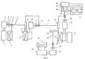
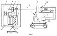
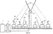
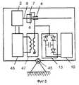
Способ и устройство для передачи электрической энергии показаны на фиг. 1, 2, 3, 4, 5. A method and apparatus for transmitting electrical energy is shown in FIG. 1, 2, 3, 4, 5.
На фиг. 1 показана схема способа и устройства для подачи электрической энергии к стационарным потребителям. In FIG. 1 shows a diagram of a method and apparatus for supplying electrical energy to stationary consumers.
На фиг. 2 - схема передачи электрической энергии на большое расстояние, содержащая большое количество источников и приемников электрической энергии. In FIG. 2 is a diagram of the transmission of electrical energy over a long distance, containing a large number of sources and receivers of electrical energy.
На фиг. 3 показана схема способа и устройства для передачи электрической энергии на транспортное средство, движущееся по произвольной траектории. In FIG. 3 shows a diagram of a method and apparatus for transmitting electrical energy to a vehicle moving along an arbitrary path.
На фиг. 4 показана схема способа и устройства для передачи электрической энергии на транспортное средство, движущееся по заданной траектории, например электромобиля на шоссе. In FIG. 4 shows a diagram of a method and apparatus for transmitting electrical energy to a vehicle moving along a predetermined path, such as an electric vehicle on a highway.
На фиг. 5 показана схема устройства для формирования проводящего канала и приема электрической энергии на транспортном средстве, движущемся по заданной траектории, например автомобиля на шоссе. In FIG. 5 shows a diagram of a device for forming a conductive channel and receiving electric energy on a vehicle moving along a predetermined path, for example, a car on a highway.
Согласно фиг. 1 источник электрической энергии 1 соединен параллельно с генератором излучения 2 и с высокочастотным высоковольтным трансформатором Тесла 3. According to FIG. 1, an
Трансформатор Тесла, изобретенный в 1891 году, представляет бессердечниковый или с незамкнутым сердечником трансформатор, первичная обмотка, которого расположена снаружи или соосно с вторичной обмоткой. Вторичная обмотка состоит из большого числа витков медной тонкой изолированной проволоки. Один конец вторичной обмотки остается свободным, а второй при передаче напряжения высокой частоты на первичную обмотку присоединяется к линии. В высоковольтной вторичной обмотке в условиях резонанса возникают высокочастотные колебания, колебания напряжением до 7 • 106 вольт. (N. Tesia, Lectures, Patents, Articles, Beograd, 1956). Трансформатор Тесла 3 соединен с формирователем 4 проводящего канала 5. Формирователь 4 выполнен в виде трубки из проводящего материала и установлен соосно с генератором излучения 2. Между формирователем 4 и генератором излучения 2 установлен прозрачный для излучения электроизолирующий экран 7, который электрически изолирует генератор излучения 2 от высокого напряжения на формирователе 4. На поверхности электроизолирующего экрана 7 со стороны, противоположной генератору излучения, нанесено электропроводящее покрытие 6, прозрачное для излучения генератора 2. Электропроводящее покрытие 6 электрически соединено с формирователем 4.The Tesla transformer, invented in 1891, is a coreless or open-core transformer, the primary winding, which is located outside or coaxially with the secondary winding. The secondary winding consists of a large number of turns of copper thin insulated wire. One end of the secondary winding remains free, and the second when transmitting high-frequency voltage to the primary winding is connected to the line. In a high-voltage secondary winding under resonance conditions, high-frequency oscillations, oscillations with a voltage of up to 7 • 106 volts arise. (N. Tesia, Lectures, Patents, Articles, Beograd, 1956). The Tesla
Внутренний диаметр D формирователя 4 равен или несколько больше диаметра пучка 8 излучения, выходящего из генератора излучения 2. Электроизолирующий экран 7 выполнен в виде пустотелого вакуумированного цилиндра и имеет два соосно расположенных окна из материала, прозрачного для излучения 8 генератора 2. The inner diameter D of the
Приемник 9 проводящего канала 5 выполнен из проводящего материала, например из стали, и изолирован от корпуса приемника электрической энергии 10 с помощью высоковольтных изоляторов 11. Приемник 9 проводящего канала 5 соединен с приемником электрической энергии с помощью понижающего трансформатора Тесла 12 или диодно-конденсаторного блока 13. Диодно-конденсаторный блок 13 используется в схемах удвоения напряжения и выполнен из двух встречно включенных диодов, соединенных с конденсатором, общая точка диодов соединена с источником питания (Электротехнический справочник, 1971 г., Изд-во Энергия, т. I, стр. 871). При подаче на диодно-конденсаторный блок переменного напряжения положительная волна переменного реактивного тока идет на одну обкладку конденсатора, а отрицательная на другую обкладку. Конденсатор будет накапливать заряды, пока напряжение на его выводах не достигнет положительной и отрицательной амплитуды переменного напряжения на общей точке диодов, тогда диоды окажутся запертыми и заряд конденсатора прекратится. Так работает простая схема выпрямителя с удвоением напряжения. The
Длина L проводящего канала 5 ограничена мощностью генератора излучения 2. Если расстояние между источником и приемником электрической энергии превышает длину L проводящего канала, устанавливают два и более генератора излучения (фиг.2). The length L of the
Согласно фиг. 2 приемник 9 первого проводящего канала 5 соединен с формирователем 14 второго проводящего канала 15. Второй проводящий канал формируется с помощью второго генератора излучения 16. Второй генератор излучения 16 изолирован от второго формирователя с помощью второго изолирующего экрана 17. Второй генератор излучения 16 получает электроэнергию от понижающего трансформатора Тесла 12 и диодного конденсаторного блока 13, соединенных с приемником 9 первого проводящего канала 5. Приемник 18 второго проводящего канала 15 соединяется с формирователем 19 третьего проводящего канала 20. According to FIG. 2, the
При необходимости передать электрическую энергию к потребителю, приемник второго проводящего канала 18 соединен с приемником электрической энергии 21 через высокочастотный понижающий трансформатор Тесла 22. If necessary, to transfer electric energy to the consumer, the receiver of the second
Генератор излучения 24 проводящего канала 20 получает электроэнергию от высокочастотного понижающего трансформатора Тесла 22. Электроизолирующий экран 25 изолирует генератор излучения 24 от высокого напряжения на формирователе 19 проводящего канала 20. Элктроизолирующий экран 25 выполнен полнотелым из электроизоляционного материала, прозрачного для излучения 8 генератора 2. The
На основе предлагаемого способа и устройства может быть создана линия передачи электрической энергии без проводов любой заданной протяженности, а также объединенная энергетическая система линий, соединяющих необходимое количество потребителей и источников электрической энергии. На фиг. 2 это иллюстрируется присоединением к приемнику 18 проводящего канала 15 приемника 26 проводящего канала 28 и использования проводящего канала 28 для подвода электроэнергии от источника электроэнергии 29, расположенного в стороне от каналов 5, 15 и 20. Источник электроэнергии 29 соединен с проводящим каналом 28 с помощью высоковольтного высокочастотного трансформатора Тесла 30 и формирователя канала 31. Проводящий канал 28 формируется с помощью генератора излучения 32 и электроизолирующего экрана 33. Генератор излучения 32 соединен с источником электроэнергии 29. Based on the proposed method and device, a transmission line of electrical energy without wires of any given length can be created, as well as an integrated energy system of lines connecting the required number of consumers and sources of electrical energy. In FIG. 2, this is illustrated by attaching to the receiver 18 a
Приемник 34 проводящего канала 20 закреплен на изоляторах 35 на корпусе приемника электрической энергии 36, который получает электрическую энергию от приемника 34 через диодно-конденсаторный блок 37. The
На фиг. 3 приемник 9 проводящего канала 5 с помощью высоковольтных изоляторов 11 установлен на крыше транспортного средства 38, например электрического трактора. В качестве электрического приемника 10 служит система электропривода управления трактором 38, которая соединена с приемником 9 через диодно-конденсаторный блок 13. In FIG. 3, the
Источник электропитания 1, генератор излучения 2, электроизолирующий экран 7 и формирователь 4 канала установлены на некотором расстоянии от транспортного средства 38 и имеют общую систему слежения 39 за транспортным средством 38. Система слежения 39 обеспечивает соединение проводящего канала 5 с приемником 9 при произвольном перемещении транспортного средства 38. В общем случае стационарный источник энергии может иметь несколько генераторов излучения 2, формирующих несколько проводящих каналов 5 для электроснабжения нескольких транспортных средств 38 одновременно. The
Для передачи электрической энергии в импульсном режиме в виде одиночных импульсов или чередующихся пакетов электрических импульсов устройство на фиг. 3 имеет синхронизатор 40 для подачи на формирователь 4 проводящего канала 5 одновременно импульсов от генератора 2 и электрических импульсов от высоковольтного высокочастотного трансформатора Тесла 3. To transmit electric energy in a pulsed mode in the form of single pulses or alternating packets of electric pulses, the device in FIG. 3 has a
На фиг. 4 стационарный источник электрической энергии 1 через высоковольтный высокочастотный трансформатор Тесла 3 соединен кабелем 41 с металлическим ленточным V-образным приемником 42, установленным на изоляторах 11 вдоль дороги 43 перемещения транспортного средства 44, например электрического автомобиля, имеющего устройство ориентации 45. In FIG. 4, a stationary source of
Генератор излучения 2 (фиг. 3), формирователь проводящего канала 4 и электроизолирующий экран 7 установлены на транспортном средстве 44 и имеют устройство ориентации 45 на металлический V-образный ленточный приемник 42. The radiation generator 2 (Fig. 3), the shaper of the
Формирователь проводящего канала соединен с электрическим приемником 45, системой электропривода и управления транспортного средства 44 и со вспомогательным маломощным источником электрической энергии 46 через вспомогательный высоковольтный высокочастотный трансформатор Тесла 47 (фиг. 5). В общем случае, по дороге может передвигаться несколько транспортных средств 43, каждый из которых соединен проводящим каналом с металлическим ленточным приемником 42. The conductive channel former is connected to the
Способ и устройство для передачи электрической энергии реализуются следующим образом. The method and device for transmitting electrical energy are implemented as follows.
Излучение от генератора излучения 2 за счет фотоионизации и ударной ионизации создает в пучке излучения 8 под действием электрического поля световой волны канал 5, обладающий повышенной проводимостью. The radiation from the
Диаметр D этого канала 5 соизмерим с диаметром лазерного луча 8 и составляет от 0,1 мм до нескольких десятков мм. The diameter D of this
Напряжение высокой частоты от источника 1 электрической энергии поступает на первичную обмотку высоковольтного высокочастотного трансформатора Тесла 3. Трансформатор Тесла 3 преобразует электрическую энергию повышенной частоты источника энергии в энергию электрических колебаний. The high-frequency voltage from the
В предлагаемом устройстве передачи электрической энергии электрические и магнитные поля пространственно разделены, также как они разделены в LC колебательном контуре. Во вторичной обмотке трансформатора Тесла 3 возбуждаются высоковольтные колебания высокой частоты, которые создают на формирователе 4 высокую напряженность электрического поля и пространственный заряд внутри трубки 6. Канал 5 внутри трубки 6 формирователя 4 ионизируется под действием высокого электрического потенциала зарядов и под действием излучения 8. В результате трубка 6 и проводящий канал 5 приобретают одинаковый потенциал и оказываются электрически соединенными друг с другом. In the proposed device for transmitting electrical energy, electric and magnetic fields are spatially separated, as well as they are separated in the LC oscillatory circuit. In the secondary winding of the
Высокая напряженность электрического поля не может по проводящему каналу 5 попасть на генератор излучения 2 и нарушить его работу благодаря наличию прозрачного электроизолирующего экрана 7. High electric field strength cannot pass through the conducting
Под действием кулоновых сил электрического поля заряды перемещаются вдоль проводящего канала 5, при этом за счет высокой напряженности электрического поля пространственного заряда происходит дополнительная фотоионизация канала 5 с образованием электрических стримлеров, с высокой скоростью (1 км/с) распространяющихся вдоль канала 5. За счет повышения электрической проводимости канала 5 происходит электрическое соединение источника энергии 1 с потребителем энергии 10 и перетекание электрических зарядов вдоль канала. Индуктивность трансформатора Тесла 3 и емкость линии 5 и нагрузки создают резонансный контур, позволяющий увеличить напряжение линии. Переменный ток, поступающий из канала 5 на вход нагрузки, является емкостным током. Реактивное внутреннее сопротивление канала 5 не создает потерь активной мощности, что обеспечивает высокий КПД передачи энергии по каналу (96-99%). Under the influence of the coulomb forces of the electric field, the charges move along the conducting
Генератор излучения 2 используется только для формирования проводящего канала, и его мощность в 50-100 раз меньше передаваемой электрической мощности. Поэтому невысокий КПД генератора излучения (10-15%) незначительно уменьшает общий КПД передачи электрической энергии. The
Пример 1. Реализация способа и устройства для передачи электрической энергии стационарным потребителям. Example 1. The implementation of the method and device for transmitting electrical energy to stationary consumers.
В качестве источника излучения 2 используют лазер на CO2 с длиной волны 10,6 мкм мощностью 1 кВт. Для создания электрического поля на формирователе 4 используют трансформатор Тесла 3 напряжением вторичной обмотки 35 кВ и частотой 30 кГц.As a
Электроизоляционный экран 7 выполнен из вакуумированного цилиндра с боковыми стенками из электроизоляционного материала, например из стекла или пластмассы и двумя соосно расположенными по оси цилиндра окнами из оптического материала, прозрачного для излучения с длиной волны 10,6 мкм. The insulating
На выходе проводящего канала 5 установлен приемник 9 диаметром 0,5 м, выполненный из тугоплавкого материала, например из титана, который электрически соединен с понижающим трансформатором Тесла 12. Напряжение вторичной обмотки понижающего трансформатора Тесла 12 подается (фиг.2) на вход питания генератора излучения 16 второго канала 15 и, при необходимости, на электрический приемник 10 потребителя электрической энергии. Если подключенные к понижающему трансформатору Тесла 12 приемники электрической энергии используют постоянный ток и ток промышленной частоты 50 Гц, то понижающий трансформатор Тесла 12 соединяют с электрическим приемником 10 через выпрямитель и инвертор. At the output of the
Электрическая мощность, передаваемая по проводящему каналу, зависит от мощности источника электрической энергии, от энергии перезарядки емкости линии и приемника и от частоты циклов перезарядки. Длина проводящего канала зависит от мощности генератора излучения и угловой расходимости излучения. The electric power transmitted through the conductive channel depends on the power of the source of electric energy, on the recharge energy of the line and receiver capacities, and on the frequency of the recharge cycles. The length of the conducting channel depends on the power of the radiation generator and the angular divergence of the radiation.
При емкости линии и приемника 1000 пФ, частоте 30 кГц и напряжении 35 кВ максимальная передаваемая мощность составит 30 МВт. При мощности лазера 1-10 кВт и расходимости излучения 1-2 угловой секунды длина одного проводящего канала составит от 100 м до 1-10 км. При использовании нескольких последовательно соединенных проводящих каналов длина линии передачи электрической энергии может быть увеличена до 100 км и более. With a line and receiver capacitance of 1000 pF, a frequency of 30 kHz and a voltage of 35 kV, the maximum transmitted power is 30 MW. With a laser power of 1-10 kW and a radiation divergence of 1-2 angular seconds, the length of one conductive channel will be from 100 m to 1-10 km. When using several series-connected conductive channels, the length of the transmission line of electric energy can be increased to 100 km or more.
При увеличении напряжения линии до 1000 кВ максимальная передаваемая мощность составит 30 млн. кВт. If the line voltage is increased to 1000 kV, the maximum transmitted power will be 30 million kW.
Пример 2. Способ и устройство передачи электрической энергии на транспортное средство, движущееся по произвольной траектории, содержит дополнительно систему слежения 39 (фиг. 3) за транспортным средством 38, содержащую оптический лазерный локатор или радиолокатор для определения координат транспортного средства, и исполнительное устройство в виде поворотной платформы, на которой установлены генератор излучения 2, формирователь проводящего канала 4 и электроизоляционный экран 7. Example 2. The method and device for transmitting electric energy to a vehicle moving along an arbitrary trajectory, further comprises a tracking system 39 (Fig. 3) for the
Пример 3. Способ и устройство для передачи электрической энергии транспортному средству, перемещающемуся по определенной траектории. В качестве примера используется гибридный автомобиль 44 (фиг. 4) с двигателем внутреннего сгорания и электрическим приводом, движущийся по дороге 43. Example 3. A method and apparatus for transmitting electrical energy to a vehicle moving along a specific path. As an example, a hybrid car 44 (Fig. 4) is used with an internal combustion engine and an electric drive moving along
На крыше автомобиля 44 установлен оптический квантовый генератор (лазер) 2 на неодимовом стекле с удвоением частоты с длиной волны 0,53 мкм электрической мощностью 0,5 кВт (фиг. 5). Соосно с излучением генератора 2 установлен электроизолирующий экран 7 и формирователь проводящего канала 4. Формирователь проводящего канала 4 соединен со вспомогательным источником электрической энергии 46 через вспомогательный высоковольтный высокочастотный трансформатор Тесла 47, которые установлены на автомобиле. Электроизоляционный экран выполнен в виде вакуумированного цилиндра из оптического стекла или в виде цилиндра из сплошного оптического стекла с полированными торцами, на которые нанесено просветляющее покрытие. На внешний торец экрана нанесено прозрачное проводящее покрытие 6, например, на основе пленок из оксидов олова и индия. Это проводящее покрытие 6 соединено проводом с формирователем 4 и с диодно-конденсаторным блоком 13. Диаметр цилиндра составляет 5-50 диаметров излучения генератора, а длина 150 мм на каждые 10 кВ напряжения на формирователе канала. An optical quantum generator (laser) 2 is mounted on the roof of the
Вдоль дороги в средней ее части на высоте 5-6 м установлен на изоляторах 11 ленточный металлический V-образный приемник 42 шириной 40-60 мм, который соединен в одном или нескольких местах вдоль дороги 43 с источником электрической энергии через высоковольтный высокочастотный трансформатор Тесла 3. Along the road in its middle part at an altitude of 5-6 m, an 11 tape metal V-shaped
Генератор излучения 2, изолирующий экран 7 и формирователь канала 4 установлены на крыше автомобиля и имеют устройство 45 для постоянной ориентации генератора излучения и проводящего канала на ленточный приемник излучения 42. The
Так как высота установки V-образного ленточного приемника 42 одинакова по длине дороги 43 и повторяет ее профиль, то для автомобиля, двигающегося в одном ряду, ориентация генератора излучения на ленточный приемник остается постоянной и не требует корректировки. При переходе в другой ряд осуществляют фиксированное изменение угла наклона генератора и при дальнейшем сохранении рядности ориентация генератора остается постоянной. Since the installation height of the V-shaped
При двухстороннем движении по 8 рядов в каждом направлении ширине ряда 4 м и V-образном расположении ленточного приемника 42 на высоте 6 м над разделительной полосой между двумя направлениями движения максимальная длина проводящего канала от крайнего ряда до ленточного приемника 42 для каждого направления составит 32 м, а минимальное расстояние составит 8 м. With two-way traffic of 8 rows in each direction, a row width of 4 m and a V-shaped arrangement of the
Формирователь проводящего канала на автомобиле соединен с системой электропривода и управления автомобиля через диодно-конденсаторный блок 13 (фиг. 5) из двух встречно включенных диодов, присоединенных к противоположным выводам конденсатора. Общий вывод обоих диодов присоединен к формирователю канала. Электрический привод присоединен к выводам конденсатора через диод. При напряжении 35 кВ на ленточном приемнике 42, частоте 30 кГц и емкости линии и конденсатора нагрузки 2000 пФ передаваемая мощность составит 60 МВт. The shaper of the conductive channel in the car is connected to the electric drive and control system of the car through a diode-capacitor unit 13 (Fig. 5) of two counter-connected diodes connected to opposite terminals of the capacitor. The common output of both diodes is connected to the channel former. An electric drive is connected to the terminals of the capacitor through a diode. With a voltage of 35 kV at the
При мощности электропривода автомобиля 60 кВт один источник электрической энергии и ленточный приемник обеспечит электрической энергией одновременное движение 1000 автомобилей. With a vehicle electric drive power of 60 kW, one source of electric energy and a tape receiver will provide simultaneous movement of 1000 cars with electric energy.
Для увеличения количества автомобилей источник электрической энергии с высоковольтным высокочастотным трансформатором Тесла 3 устанавливают через определенное расстояние вдоль дороги 43 и соединяют с ленточным приемником 42 с помощью кабеля 41. To increase the number of cars, an electric power source with a
В качестве генератора излучения для формирования проводящего канала может быть использован генератор рентгеновского и другого излучения, генератор аэрозолей и другие устройства, создающие повышенную проводимость канала по оси пучка излучения. An X-ray and other radiation generator, an aerosol generator, and other devices that create increased channel conductivity along the axis of the radiation beam can be used as a radiation generator to form a conducting channel.
Способ и устройство могут быть использованы для передачи электрической энергии на самолеты, шары-зонды, ракеты и низкоорбитальные спутники как в непрерывном, так в импульсивном режиме. The method and device can be used to transfer electrical energy to airplanes, balloons, rockets and low-orbit satellites in both continuous and pulsed mode.
Claims (14)
Translated fromRussianPriority Applications (1)
| Application Number | Priority Date | Filing Date | Title |
|---|---|---|---|
| RU99105452/09ARU2143775C1 (en) | 1999-03-25 | 1999-03-25 | Power transmission method and device |
Applications Claiming Priority (1)
| Application Number | Priority Date | Filing Date | Title |
|---|---|---|---|
| RU99105452/09ARU2143775C1 (en) | 1999-03-25 | 1999-03-25 | Power transmission method and device |
Publications (1)
| Publication Number | Publication Date |
|---|---|
| RU2143775C1true RU2143775C1 (en) | 1999-12-27 |
Family
ID=20217301
Family Applications (1)
| Application Number | Title | Priority Date | Filing Date |
|---|---|---|---|
| RU99105452/09ARU2143775C1 (en) | 1999-03-25 | 1999-03-25 | Power transmission method and device |
Country Status (1)
| Country | Link |
|---|---|
| RU (1) | RU2143775C1 (en) |
Cited By (100)
| Publication number | Priority date | Publication date | Assignee | Title |
|---|---|---|---|---|
| RU2172546C1 (en)* | 2000-01-24 | 2001-08-20 | Стребков Дмитрий Семенович | Method and device for electrical energy transmission |
| RU2183376C2 (en)* | 2000-07-03 | 2002-06-10 | Стребков Дмитрий Семенович | Procedure and gear to transmit electric energy ( alternatives ) |
| RU2245598C1 (en)* | 2003-07-11 | 2005-01-27 | Стребков Дмитрий Семенович | Method and device for electrical energy transmission |
| RU2255405C2 (en)* | 2003-02-07 | 2005-06-27 | Государственное научное учреждение Всероссийский научно-исследовательский институт электрификации сельского хозяйства (ГНУ ВИЭСХ) | Method and device for electrical energy transmission |
| RU2259002C2 (en)* | 2003-03-25 | 2005-08-20 | Государственное научное учреждение Всероссийский научно-исследовательский институт электрификации сельского хозяйства (ГНУ ВИЭСХ) | Solar-power system |
| RU2273939C1 (en)* | 2004-12-01 | 2006-04-10 | Государственное научное учреждение Всероссийский научно-исследовательский институт электрификации сельского хозяйства (ГНУ ВИЭСХ) | Method and device for transferring electric energy (variants) |
| RU2286585C2 (en)* | 2004-02-17 | 2006-10-27 | Открытое акционерное общество "Научно-исследовательский институт измерительных приборов" (ОАО "НИИИП") | Method of radiolocation and device for its realization |
| RU2310964C1 (en)* | 2006-02-10 | 2007-11-20 | Российская Академия сельскохозяйственных наук Государственное научное учреждение Всероссийский научно-исследовательский институт электрификации сельского хозяйства (ГНУ ВИЭСХ РОССЕЛЬХОЗАКАДЕМИИ) | Electrical energy transmission method and device |
| RU2322745C2 (en)* | 2006-05-18 | 2008-04-20 | Юрий Альбертович Мартынов | Method and device for wireless transmission of electric power |
| RU2341860C2 (en)* | 2006-07-04 | 2008-12-20 | Виктор Иванович Петрик | Method and device for transmission of electric power (versions) |
| RU2342761C1 (en)* | 2007-09-07 | 2008-12-27 | Российская Академия сельскохозяйственных наук Государственное научное учреждение Всероссийский научно-исследовательский институт электрификации сельского хозяйства (ГНУ ВИЭСХ РОССЕЛЬХОЗАКАДЕМИИ) | Method and device for electric energy transmission (versions) |
| WO2009025631A1 (en)* | 2007-08-20 | 2009-02-26 | Vitalii Grigorovich Kriuk | Wireless electric power transmission device |
| RU2393612C1 (en)* | 2008-12-29 | 2010-06-27 | Государственное образовательное учреждение высшего профессионального образования "Кубанский государственный технологический университет" (ГОУВПО "КубГТУ") | Method of electric power transfer in high vacuum and device for method implementation |
| RU2400005C1 (en)* | 2009-05-20 | 2010-09-20 | Виктор Викторович Аполлонов | Method of creating current-conducting channels in non-conducting medium |
| RU2403154C2 (en)* | 2005-05-24 | 2010-11-10 | РИЭРДЕН, ЭлЭлСи | System and method for vehicle power supply using rf-band generators |
| RU2409883C1 (en)* | 2009-09-11 | 2011-01-20 | Российская Академия сельскохозяйственных наук Государственное научное учреждение Всероссийский научно-исследовательский институт электрификации сельского хозяйства (ГНУ ВИЭСХ РОССЕЛЬХОЗАКАДЕМИИ) | Electric energy transmission method and device |
| RU2443578C1 (en)* | 2010-06-18 | 2012-02-27 | Российская академия сельскохозяйственных наук Государственное научное учреждение Всероссийский научно-исследовательский институт электрификации сельского хозяйства Российской академии сельскохозяйственных наук (ГНУ ВИЭСХ Россельхозакадемии) | Device for power supply and control of electrically driven transport facilities |
| RU2454799C2 (en)* | 2006-03-21 | 2012-06-27 | МУРАТА МЭНЬЮФЭКЧЕРИНГ Ко., Лтд | Device for electrostatic power transmission through non-conducting medium |
| RU2459340C2 (en)* | 2010-09-21 | 2012-08-20 | Российская академия сельскохозяйственных наук Государственное научное учреждение Всероссийский научно-исследовательский институт электрификации сельского хозяйства Российской академии сельскохозяйственных наук (ГНУ ВИЭСХ Россельхозакадемии) | Method and device for transmission of power |
| WO2012161991A1 (en)* | 2011-05-17 | 2012-11-29 | Moore Leslie A | Power generation system |
| US8469122B2 (en) | 2005-05-24 | 2013-06-25 | Rearden, Llc | System and method for powering vehicle using radio frequency signals and feedback |
| RU2488495C1 (en)* | 2009-05-14 | 2013-07-27 | Тойота Дзидося Кабусики Кайся | Contactless power intake device and vehicle incorporating said device |
| RU2490146C2 (en)* | 2011-10-31 | 2013-08-20 | Государственное научное учреждение Всероссийский научно-исследовательский институт электрификации сельского хозяйства Российской академии сельскохозяйственных наук (ГНУ ВИЭСХ Россельхозакадемии) | System and method for electric power contactless transfer to vehicle |
| RU2534492C1 (en)* | 2010-09-09 | 2014-11-27 | Сименс Акциенгезелльшафт | Power supply unit, device and system with such unit and method of power supply to line portion related to vehicle track |
| RU2538160C2 (en)* | 2013-03-14 | 2015-01-10 | Александр Александрович Звонов | Method and device for wireless electric power supply to remote consumers of electrical energy via laser beam |
| US9496921B1 (en) | 2015-09-09 | 2016-11-15 | Cpg Technologies | Hybrid guided surface wave communication |
| US9819403B2 (en) | 2004-04-02 | 2017-11-14 | Rearden, Llc | System and method for managing handoff of a client between different distributed-input-distributed-output (DIDO) networks based on detected velocity of the client |
| US9826537B2 (en) | 2004-04-02 | 2017-11-21 | Rearden, Llc | System and method for managing inter-cluster handoff of clients which traverse multiple DIDO clusters |
| US9857402B2 (en) | 2015-09-08 | 2018-01-02 | CPG Technologies, L.L.C. | Measuring and reporting power received from guided surface waves |
| US9859707B2 (en) | 2014-09-11 | 2018-01-02 | Cpg Technologies, Llc | Simultaneous multifrequency receive circuits |
| US9882397B2 (en) | 2014-09-11 | 2018-01-30 | Cpg Technologies, Llc | Guided surface wave transmission of multiple frequencies in a lossy media |
| US9882436B2 (en) | 2015-09-09 | 2018-01-30 | Cpg Technologies, Llc | Return coupled wireless power transmission |
| RU2643317C1 (en)* | 2015-01-29 | 2018-01-31 | Ниссан Мотор Ко., Лтд. | Parking assistance device and parking assistance method |
| US9887558B2 (en) | 2015-09-09 | 2018-02-06 | Cpg Technologies, Llc | Wired and wireless power distribution coexistence |
| US9885742B2 (en) | 2015-09-09 | 2018-02-06 | Cpg Technologies, Llc | Detecting unauthorized consumption of electrical energy |
| US9887587B2 (en) | 2014-09-11 | 2018-02-06 | Cpg Technologies, Llc | Variable frequency receivers for guided surface wave transmissions |
| US9887585B2 (en) | 2015-09-08 | 2018-02-06 | Cpg Technologies, Llc | Changing guided surface wave transmissions to follow load conditions |
| US9887557B2 (en) | 2014-09-11 | 2018-02-06 | Cpg Technologies, Llc | Hierarchical power distribution |
| US9887556B2 (en) | 2014-09-11 | 2018-02-06 | Cpg Technologies, Llc | Chemically enhanced isolated capacitance |
| US9893402B2 (en) | 2014-09-11 | 2018-02-13 | Cpg Technologies, Llc | Superposition of guided surface waves on lossy media |
| US9893403B2 (en) | 2015-09-11 | 2018-02-13 | Cpg Technologies, Llc | Enhanced guided surface waveguide probe |
| US9899718B2 (en) | 2015-09-11 | 2018-02-20 | Cpg Technologies, Llc | Global electrical power multiplication |
| US9912031B2 (en) | 2013-03-07 | 2018-03-06 | Cpg Technologies, Llc | Excitation and use of guided surface wave modes on lossy media |
| US9910144B2 (en) | 2013-03-07 | 2018-03-06 | Cpg Technologies, Llc | Excitation and use of guided surface wave modes on lossy media |
| US9916485B1 (en) | 2015-09-09 | 2018-03-13 | Cpg Technologies, Llc | Method of managing objects using an electromagnetic guided surface waves over a terrestrial medium |
| US9923385B2 (en) | 2015-06-02 | 2018-03-20 | Cpg Technologies, Llc | Excitation and use of guided surface waves |
| US9923657B2 (en) | 2013-03-12 | 2018-03-20 | Rearden, Llc | Systems and methods for exploiting inter-cell multiplexing gain in wireless cellular systems via distributed input distributed output technology |
| US9921256B2 (en) | 2015-09-08 | 2018-03-20 | Cpg Technologies, Llc | Field strength monitoring for optimal performance |
| US9927477B1 (en) | 2015-09-09 | 2018-03-27 | Cpg Technologies, Llc | Object identification system and method |
| US9941566B2 (en) | 2014-09-10 | 2018-04-10 | Cpg Technologies, Llc | Excitation and use of guided surface wave modes on lossy media |
| US9960470B2 (en) | 2014-09-11 | 2018-05-01 | Cpg Technologies, Llc | Site preparation for guided surface wave transmission in a lossy media |
| US9973037B1 (en) | 2015-09-09 | 2018-05-15 | Cpg Technologies, Llc | Object identification system and method |
| US9973246B2 (en) | 2013-03-12 | 2018-05-15 | Rearden, Llc | Systems and methods for exploiting inter-cell multiplexing gain in wireless cellular systems via distributed input distributed output technology |
| US9997040B2 (en) | 2015-09-08 | 2018-06-12 | Cpg Technologies, Llc | Global emergency and disaster transmission |
| US10001553B2 (en) | 2014-09-11 | 2018-06-19 | Cpg Technologies, Llc | Geolocation with guided surface waves |
| US10027131B2 (en) | 2015-09-09 | 2018-07-17 | CPG Technologies, Inc. | Classification of transmission |
| US10027177B2 (en) | 2015-09-09 | 2018-07-17 | Cpg Technologies, Llc | Load shedding in a guided surface wave power delivery system |
| US10027116B2 (en) | 2014-09-11 | 2018-07-17 | Cpg Technologies, Llc | Adaptation of polyphase waveguide probes |
| US10031208B2 (en) | 2015-09-09 | 2018-07-24 | Cpg Technologies, Llc | Object identification system and method |
| US10033198B2 (en) | 2014-09-11 | 2018-07-24 | Cpg Technologies, Llc | Frequency division multiplexing for wireless power providers |
| US10033197B2 (en) | 2015-09-09 | 2018-07-24 | Cpg Technologies, Llc | Object identification system and method |
| US10062944B2 (en) | 2015-09-09 | 2018-08-28 | CPG Technologies, Inc. | Guided surface waveguide probes |
| US10063095B2 (en) | 2015-09-09 | 2018-08-28 | CPG Technologies, Inc. | Deterring theft in wireless power systems |
| US10074993B2 (en) | 2014-09-11 | 2018-09-11 | Cpg Technologies, Llc | Simultaneous transmission and reception of guided surface waves |
| US10079573B2 (en) | 2014-09-11 | 2018-09-18 | Cpg Technologies, Llc | Embedding data on a power signal |
| US10084223B2 (en) | 2014-09-11 | 2018-09-25 | Cpg Technologies, Llc | Modulated guided surface waves |
| US10103452B2 (en) | 2015-09-10 | 2018-10-16 | Cpg Technologies, Llc | Hybrid phased array transmission |
| US10101444B2 (en) | 2014-09-11 | 2018-10-16 | Cpg Technologies, Llc | Remote surface sensing using guided surface wave modes on lossy media |
| US10122218B2 (en) | 2015-09-08 | 2018-11-06 | Cpg Technologies, Llc | Long distance transmission of offshore power |
| US10135301B2 (en) | 2015-09-09 | 2018-11-20 | Cpg Technologies, Llc | Guided surface waveguide probes |
| US10141622B2 (en) | 2015-09-10 | 2018-11-27 | Cpg Technologies, Llc | Mobile guided surface waveguide probes and receivers |
| US10175203B2 (en) | 2014-09-11 | 2019-01-08 | Cpg Technologies, Llc | Subsurface sensing using guided surface wave modes on lossy media |
| US10175048B2 (en) | 2015-09-10 | 2019-01-08 | Cpg Technologies, Llc | Geolocation using guided surface waves |
| US10193229B2 (en) | 2015-09-10 | 2019-01-29 | Cpg Technologies, Llc | Magnetic coils having cores with high magnetic permeability |
| US10193595B2 (en) | 2015-06-02 | 2019-01-29 | Cpg Technologies, Llc | Excitation and use of guided surface waves |
| US10205326B2 (en) | 2015-09-09 | 2019-02-12 | Cpg Technologies, Llc | Adaptation of energy consumption node for guided surface wave reception |
| US10230270B2 (en) | 2015-09-09 | 2019-03-12 | Cpg Technologies, Llc | Power internal medical devices with guided surface waves |
| US10277290B2 (en) | 2004-04-02 | 2019-04-30 | Rearden, Llc | Systems and methods to exploit areas of coherence in wireless systems |
| US10312747B2 (en) | 2015-09-10 | 2019-06-04 | Cpg Technologies, Llc | Authentication to enable/disable guided surface wave receive equipment |
| US10324163B2 (en) | 2015-09-10 | 2019-06-18 | Cpg Technologies, Llc | Geolocation using guided surface waves |
| US10333604B2 (en) | 2004-04-02 | 2019-06-25 | Rearden, Llc | System and method for distributed antenna wireless communications |
| US10396566B2 (en) | 2015-09-10 | 2019-08-27 | Cpg Technologies, Llc | Geolocation using guided surface waves |
| US10408915B2 (en) | 2015-09-10 | 2019-09-10 | Cpg Technologies, Llc | Geolocation using guided surface waves |
| US10408916B2 (en) | 2015-09-10 | 2019-09-10 | Cpg Technologies, Llc | Geolocation using guided surface waves |
| US10425134B2 (en) | 2004-04-02 | 2019-09-24 | Rearden, Llc | System and methods for planned evolution and obsolescence of multiuser spectrum |
| US10447342B1 (en) | 2017-03-07 | 2019-10-15 | Cpg Technologies, Llc | Arrangements for coupling the primary coil to the secondary coil |
| US10488535B2 (en) | 2013-03-12 | 2019-11-26 | Rearden, Llc | Apparatus and method for capturing still images and video using diffraction coded imaging techniques |
| US10498393B2 (en) | 2014-09-11 | 2019-12-03 | Cpg Technologies, Llc | Guided surface wave powered sensing devices |
| US10498006B2 (en) | 2015-09-10 | 2019-12-03 | Cpg Technologies, Llc | Guided surface wave transmissions that illuminate defined regions |
| US10547358B2 (en) | 2013-03-15 | 2020-01-28 | Rearden, Llc | Systems and methods for radio frequency calibration exploiting channel reciprocity in distributed input distributed output wireless communications |
| RU2713208C1 (en)* | 2019-06-20 | 2020-02-04 | Федеральное государственное бюджетное научное учреждение "Федеральный научный агроинженерный центр ВИМ" (ФГБНУ ФНАЦ ВИМ) | Apparatus and method of transmitting electrical power |
| US10559893B1 (en) | 2015-09-10 | 2020-02-11 | Cpg Technologies, Llc | Pulse protection circuits to deter theft |
| US10560147B1 (en) | 2017-03-07 | 2020-02-11 | Cpg Technologies, Llc | Guided surface waveguide probe control system |
| US10559866B2 (en) | 2017-03-07 | 2020-02-11 | Cpg Technologies, Inc | Measuring operational parameters at the guided surface waveguide probe |
| US10559867B2 (en) | 2017-03-07 | 2020-02-11 | Cpg Technologies, Llc | Minimizing atmospheric discharge within a guided surface waveguide probe |
| US10581492B1 (en) | 2017-03-07 | 2020-03-03 | Cpg Technologies, Llc | Heat management around a phase delay coil in a probe |
| US10630111B2 (en) | 2017-03-07 | 2020-04-21 | Cpg Technologies, Llc | Adjustment of guided surface waveguide probe operation |
| US10727907B2 (en) | 2004-07-30 | 2020-07-28 | Rearden, Llc | Systems and methods to enhance spatial diversity in distributed input distributed output wireless systems |
| US10998993B2 (en) | 2015-09-10 | 2021-05-04 | CPG Technologies, Inc. | Global time synchronization using a guided surface wave |
| US11189917B2 (en) | 2014-04-16 | 2021-11-30 | Rearden, Llc | Systems and methods for distributing radioheads |
Citations (5)
| Publication number | Priority date | Publication date | Assignee | Title |
|---|---|---|---|---|
| US3719829A (en)* | 1970-04-10 | 1973-03-06 | Versar Inc | Laser beam techniques |
| US4414461A (en)* | 1981-08-21 | 1983-11-08 | The United States Of America As Represented By The Secretary Of The Navy | Laser pumped superconductive energy storage system |
| WO1989010651A1 (en)* | 1988-04-28 | 1989-11-02 | Every-Sys Ag | Electric transmission device |
| DE4034669A1 (en)* | 1990-10-31 | 1992-05-07 | Joergen Brosow | METHOD FOR REMOTE TRANSMISSION OF ENERGY |
| DE4136058A1 (en)* | 1991-10-31 | 1993-05-06 | Siegfried O-1055 Berlin De Stargard | Laser based wireless transmission of HV power - using laser rod array transmitting current matching earths ballistic properties to receiving aerial resembling lightning conductor |
- 1999
- 1999-03-25RURU99105452/09Apatent/RU2143775C1/ennot_activeIP Right Cessation
Patent Citations (5)
| Publication number | Priority date | Publication date | Assignee | Title |
|---|---|---|---|---|
| US3719829A (en)* | 1970-04-10 | 1973-03-06 | Versar Inc | Laser beam techniques |
| US4414461A (en)* | 1981-08-21 | 1983-11-08 | The United States Of America As Represented By The Secretary Of The Navy | Laser pumped superconductive energy storage system |
| WO1989010651A1 (en)* | 1988-04-28 | 1989-11-02 | Every-Sys Ag | Electric transmission device |
| DE4034669A1 (en)* | 1990-10-31 | 1992-05-07 | Joergen Brosow | METHOD FOR REMOTE TRANSMISSION OF ENERGY |
| DE4136058A1 (en)* | 1991-10-31 | 1993-05-06 | Siegfried O-1055 Berlin De Stargard | Laser based wireless transmission of HV power - using laser rod array transmitting current matching earths ballistic properties to receiving aerial resembling lightning conductor |
Cited By (127)
| Publication number | Priority date | Publication date | Assignee | Title |
|---|---|---|---|---|
| RU2172546C1 (en)* | 2000-01-24 | 2001-08-20 | Стребков Дмитрий Семенович | Method and device for electrical energy transmission |
| RU2183376C2 (en)* | 2000-07-03 | 2002-06-10 | Стребков Дмитрий Семенович | Procedure and gear to transmit electric energy ( alternatives ) |
| RU2255405C2 (en)* | 2003-02-07 | 2005-06-27 | Государственное научное учреждение Всероссийский научно-исследовательский институт электрификации сельского хозяйства (ГНУ ВИЭСХ) | Method and device for electrical energy transmission |
| RU2259002C2 (en)* | 2003-03-25 | 2005-08-20 | Государственное научное учреждение Всероссийский научно-исследовательский институт электрификации сельского хозяйства (ГНУ ВИЭСХ) | Solar-power system |
| RU2245598C1 (en)* | 2003-07-11 | 2005-01-27 | Стребков Дмитрий Семенович | Method and device for electrical energy transmission |
| RU2286585C2 (en)* | 2004-02-17 | 2006-10-27 | Открытое акционерное общество "Научно-исследовательский институт измерительных приборов" (ОАО "НИИИП") | Method of radiolocation and device for its realization |
| US10333604B2 (en) | 2004-04-02 | 2019-06-25 | Rearden, Llc | System and method for distributed antenna wireless communications |
| US10425134B2 (en) | 2004-04-02 | 2019-09-24 | Rearden, Llc | System and methods for planned evolution and obsolescence of multiuser spectrum |
| US10277290B2 (en) | 2004-04-02 | 2019-04-30 | Rearden, Llc | Systems and methods to exploit areas of coherence in wireless systems |
| US9826537B2 (en) | 2004-04-02 | 2017-11-21 | Rearden, Llc | System and method for managing inter-cluster handoff of clients which traverse multiple DIDO clusters |
| US9819403B2 (en) | 2004-04-02 | 2017-11-14 | Rearden, Llc | System and method for managing handoff of a client between different distributed-input-distributed-output (DIDO) networks based on detected velocity of the client |
| US10727907B2 (en) | 2004-07-30 | 2020-07-28 | Rearden, Llc | Systems and methods to enhance spatial diversity in distributed input distributed output wireless systems |
| RU2273939C1 (en)* | 2004-12-01 | 2006-04-10 | Государственное научное учреждение Всероссийский научно-исследовательский институт электрификации сельского хозяйства (ГНУ ВИЭСХ) | Method and device for transferring electric energy (variants) |
| US8469122B2 (en) | 2005-05-24 | 2013-06-25 | Rearden, Llc | System and method for powering vehicle using radio frequency signals and feedback |
| RU2403154C2 (en)* | 2005-05-24 | 2010-11-10 | РИЭРДЕН, ЭлЭлСи | System and method for vehicle power supply using rf-band generators |
| RU2310964C1 (en)* | 2006-02-10 | 2007-11-20 | Российская Академия сельскохозяйственных наук Государственное научное учреждение Всероссийский научно-исследовательский институт электрификации сельского хозяйства (ГНУ ВИЭСХ РОССЕЛЬХОЗАКАДЕМИИ) | Electrical energy transmission method and device |
| RU2454799C2 (en)* | 2006-03-21 | 2012-06-27 | МУРАТА МЭНЬЮФЭКЧЕРИНГ Ко., Лтд | Device for electrostatic power transmission through non-conducting medium |
| RU2322745C2 (en)* | 2006-05-18 | 2008-04-20 | Юрий Альбертович Мартынов | Method and device for wireless transmission of electric power |
| RU2341860C2 (en)* | 2006-07-04 | 2008-12-20 | Виктор Иванович Петрик | Method and device for transmission of electric power (versions) |
| WO2009025631A1 (en)* | 2007-08-20 | 2009-02-26 | Vitalii Grigorovich Kriuk | Wireless electric power transmission device |
| RU2342761C1 (en)* | 2007-09-07 | 2008-12-27 | Российская Академия сельскохозяйственных наук Государственное научное учреждение Всероссийский научно-исследовательский институт электрификации сельского хозяйства (ГНУ ВИЭСХ РОССЕЛЬХОЗАКАДЕМИИ) | Method and device for electric energy transmission (versions) |
| RU2393612C1 (en)* | 2008-12-29 | 2010-06-27 | Государственное образовательное учреждение высшего профессионального образования "Кубанский государственный технологический университет" (ГОУВПО "КубГТУ") | Method of electric power transfer in high vacuum and device for method implementation |
| RU2488495C1 (en)* | 2009-05-14 | 2013-07-27 | Тойота Дзидося Кабусики Кайся | Contactless power intake device and vehicle incorporating said device |
| RU2400005C1 (en)* | 2009-05-20 | 2010-09-20 | Виктор Викторович Аполлонов | Method of creating current-conducting channels in non-conducting medium |
| RU2409883C1 (en)* | 2009-09-11 | 2011-01-20 | Российская Академия сельскохозяйственных наук Государственное научное учреждение Всероссийский научно-исследовательский институт электрификации сельского хозяйства (ГНУ ВИЭСХ РОССЕЛЬХОЗАКАДЕМИИ) | Electric energy transmission method and device |
| RU2443578C1 (en)* | 2010-06-18 | 2012-02-27 | Российская академия сельскохозяйственных наук Государственное научное учреждение Всероссийский научно-исследовательский институт электрификации сельского хозяйства Российской академии сельскохозяйственных наук (ГНУ ВИЭСХ Россельхозакадемии) | Device for power supply and control of electrically driven transport facilities |
| RU2534492C1 (en)* | 2010-09-09 | 2014-11-27 | Сименс Акциенгезелльшафт | Power supply unit, device and system with such unit and method of power supply to line portion related to vehicle track |
| RU2459340C2 (en)* | 2010-09-21 | 2012-08-20 | Российская академия сельскохозяйственных наук Государственное научное учреждение Всероссийский научно-исследовательский институт электрификации сельского хозяйства Российской академии сельскохозяйственных наук (ГНУ ВИЭСХ Россельхозакадемии) | Method and device for transmission of power |
| WO2012161991A1 (en)* | 2011-05-17 | 2012-11-29 | Moore Leslie A | Power generation system |
| RU2490146C2 (en)* | 2011-10-31 | 2013-08-20 | Государственное научное учреждение Всероссийский научно-исследовательский институт электрификации сельского хозяйства Российской академии сельскохозяйственных наук (ГНУ ВИЭСХ Россельхозакадемии) | System and method for electric power contactless transfer to vehicle |
| US9912031B2 (en) | 2013-03-07 | 2018-03-06 | Cpg Technologies, Llc | Excitation and use of guided surface wave modes on lossy media |
| US10680306B2 (en) | 2013-03-07 | 2020-06-09 | CPG Technologies, Inc. | Excitation and use of guided surface wave modes on lossy media |
| US9910144B2 (en) | 2013-03-07 | 2018-03-06 | Cpg Technologies, Llc | Excitation and use of guided surface wave modes on lossy media |
| US10488535B2 (en) | 2013-03-12 | 2019-11-26 | Rearden, Llc | Apparatus and method for capturing still images and video using diffraction coded imaging techniques |
| US12147001B2 (en) | 2013-03-12 | 2024-11-19 | Rearden, Llc | Apparatus and method for capturing still images and video using diffraction coded imaging techniques |
| US9923657B2 (en) | 2013-03-12 | 2018-03-20 | Rearden, Llc | Systems and methods for exploiting inter-cell multiplexing gain in wireless cellular systems via distributed input distributed output technology |
| US9973246B2 (en) | 2013-03-12 | 2018-05-15 | Rearden, Llc | Systems and methods for exploiting inter-cell multiplexing gain in wireless cellular systems via distributed input distributed output technology |
| RU2538160C2 (en)* | 2013-03-14 | 2015-01-10 | Александр Александрович Звонов | Method and device for wireless electric power supply to remote consumers of electrical energy via laser beam |
| US11146313B2 (en) | 2013-03-15 | 2021-10-12 | Rearden, Llc | Systems and methods for radio frequency calibration exploiting channel reciprocity in distributed input distributed output wireless communications |
| US10547358B2 (en) | 2013-03-15 | 2020-01-28 | Rearden, Llc | Systems and methods for radio frequency calibration exploiting channel reciprocity in distributed input distributed output wireless communications |
| US11189917B2 (en) | 2014-04-16 | 2021-11-30 | Rearden, Llc | Systems and methods for distributing radioheads |
| US9941566B2 (en) | 2014-09-10 | 2018-04-10 | Cpg Technologies, Llc | Excitation and use of guided surface wave modes on lossy media |
| US10998604B2 (en) | 2014-09-10 | 2021-05-04 | Cpg Technologies, Llc | Excitation and use of guided surface wave modes on lossy media |
| US10224589B2 (en) | 2014-09-10 | 2019-03-05 | Cpg Technologies, Llc | Excitation and use of guided surface wave modes on lossy media |
| US9887556B2 (en) | 2014-09-11 | 2018-02-06 | Cpg Technologies, Llc | Chemically enhanced isolated capacitance |
| US10135298B2 (en) | 2014-09-11 | 2018-11-20 | Cpg Technologies, Llc | Variable frequency receivers for guided surface wave transmissions |
| US10175203B2 (en) | 2014-09-11 | 2019-01-08 | Cpg Technologies, Llc | Subsurface sensing using guided surface wave modes on lossy media |
| US9893402B2 (en) | 2014-09-11 | 2018-02-13 | Cpg Technologies, Llc | Superposition of guided surface waves on lossy media |
| US10177571B2 (en) | 2014-09-11 | 2019-01-08 | Cpg Technologies, Llc | Simultaneous multifrequency receive circuits |
| US10193353B2 (en) | 2014-09-11 | 2019-01-29 | Cpg Technologies, Llc | Guided surface wave transmission of multiple frequencies in a lossy media |
| US9887557B2 (en) | 2014-09-11 | 2018-02-06 | Cpg Technologies, Llc | Hierarchical power distribution |
| US9960470B2 (en) | 2014-09-11 | 2018-05-01 | Cpg Technologies, Llc | Site preparation for guided surface wave transmission in a lossy media |
| US10153638B2 (en) | 2014-09-11 | 2018-12-11 | Cpg Technologies, Llc | Adaptation of polyphase waveguide probes |
| US9859707B2 (en) | 2014-09-11 | 2018-01-02 | Cpg Technologies, Llc | Simultaneous multifrequency receive circuits |
| US10498393B2 (en) | 2014-09-11 | 2019-12-03 | Cpg Technologies, Llc | Guided surface wave powered sensing devices |
| US10001553B2 (en) | 2014-09-11 | 2018-06-19 | Cpg Technologies, Llc | Geolocation with guided surface waves |
| US9887587B2 (en) | 2014-09-11 | 2018-02-06 | Cpg Technologies, Llc | Variable frequency receivers for guided surface wave transmissions |
| US10381843B2 (en) | 2014-09-11 | 2019-08-13 | Cpg Technologies, Llc | Hierarchical power distribution |
| US10027116B2 (en) | 2014-09-11 | 2018-07-17 | Cpg Technologies, Llc | Adaptation of polyphase waveguide probes |
| US10355481B2 (en) | 2014-09-11 | 2019-07-16 | Cpg Technologies, Llc | Simultaneous multifrequency receive circuits |
| US10033198B2 (en) | 2014-09-11 | 2018-07-24 | Cpg Technologies, Llc | Frequency division multiplexing for wireless power providers |
| US10355480B2 (en) | 2014-09-11 | 2019-07-16 | Cpg Technologies, Llc | Adaptation of polyphase waveguide probes |
| US10320200B2 (en) | 2014-09-11 | 2019-06-11 | Cpg Technologies, Llc | Chemically enhanced isolated capacitance |
| US9882397B2 (en) | 2014-09-11 | 2018-01-30 | Cpg Technologies, Llc | Guided surface wave transmission of multiple frequencies in a lossy media |
| US10074993B2 (en) | 2014-09-11 | 2018-09-11 | Cpg Technologies, Llc | Simultaneous transmission and reception of guided surface waves |
| US10079573B2 (en) | 2014-09-11 | 2018-09-18 | Cpg Technologies, Llc | Embedding data on a power signal |
| US10084223B2 (en) | 2014-09-11 | 2018-09-25 | Cpg Technologies, Llc | Modulated guided surface waves |
| US10320045B2 (en) | 2014-09-11 | 2019-06-11 | Cpg Technologies, Llc | Superposition of guided surface waves on lossy media |
| US10101444B2 (en) | 2014-09-11 | 2018-10-16 | Cpg Technologies, Llc | Remote surface sensing using guided surface wave modes on lossy media |
| RU2643317C1 (en)* | 2015-01-29 | 2018-01-31 | Ниссан Мотор Ко., Лтд. | Parking assistance device and parking assistance method |
| US9923385B2 (en) | 2015-06-02 | 2018-03-20 | Cpg Technologies, Llc | Excitation and use of guided surface waves |
| US10193595B2 (en) | 2015-06-02 | 2019-01-29 | Cpg Technologies, Llc | Excitation and use of guided surface waves |
| US10122218B2 (en) | 2015-09-08 | 2018-11-06 | Cpg Technologies, Llc | Long distance transmission of offshore power |
| US10132845B2 (en) | 2015-09-08 | 2018-11-20 | Cpg Technologies, Llc | Measuring and reporting power received from guided surface waves |
| US9997040B2 (en) | 2015-09-08 | 2018-06-12 | Cpg Technologies, Llc | Global emergency and disaster transmission |
| US10320233B2 (en) | 2015-09-08 | 2019-06-11 | Cpg Technologies, Llc | Changing guided surface wave transmissions to follow load conditions |
| US9887585B2 (en) | 2015-09-08 | 2018-02-06 | Cpg Technologies, Llc | Changing guided surface wave transmissions to follow load conditions |
| US10467876B2 (en) | 2015-09-08 | 2019-11-05 | Cpg Technologies, Llc | Global emergency and disaster transmission |
| US9921256B2 (en) | 2015-09-08 | 2018-03-20 | Cpg Technologies, Llc | Field strength monitoring for optimal performance |
| US10274527B2 (en) | 2015-09-08 | 2019-04-30 | CPG Technologies, Inc. | Field strength monitoring for optimal performance |
| US9857402B2 (en) | 2015-09-08 | 2018-01-02 | CPG Technologies, L.L.C. | Measuring and reporting power received from guided surface waves |
| US10062944B2 (en) | 2015-09-09 | 2018-08-28 | CPG Technologies, Inc. | Guided surface waveguide probes |
| US10516303B2 (en) | 2015-09-09 | 2019-12-24 | Cpg Technologies, Llc | Return coupled wireless power transmission |
| US9885742B2 (en) | 2015-09-09 | 2018-02-06 | Cpg Technologies, Llc | Detecting unauthorized consumption of electrical energy |
| US10230270B2 (en) | 2015-09-09 | 2019-03-12 | Cpg Technologies, Llc | Power internal medical devices with guided surface waves |
| US9887558B2 (en) | 2015-09-09 | 2018-02-06 | Cpg Technologies, Llc | Wired and wireless power distribution coexistence |
| US10148132B2 (en) | 2015-09-09 | 2018-12-04 | Cpg Technologies, Llc | Return coupled wireless power transmission |
| US9882606B2 (en) | 2015-09-09 | 2018-01-30 | Cpg Technologies, Llc | Hybrid guided surface wave communication |
| US9882436B2 (en) | 2015-09-09 | 2018-01-30 | Cpg Technologies, Llc | Return coupled wireless power transmission |
| US10135301B2 (en) | 2015-09-09 | 2018-11-20 | Cpg Technologies, Llc | Guided surface waveguide probes |
| US9496921B1 (en) | 2015-09-09 | 2016-11-15 | Cpg Technologies | Hybrid guided surface wave communication |
| US10536037B2 (en) | 2015-09-09 | 2020-01-14 | Cpg Technologies, Llc | Load shedding in a guided surface wave power delivery system |
| US10027131B2 (en) | 2015-09-09 | 2018-07-17 | CPG Technologies, Inc. | Classification of transmission |
| US10063095B2 (en) | 2015-09-09 | 2018-08-28 | CPG Technologies, Inc. | Deterring theft in wireless power systems |
| US10333316B2 (en) | 2015-09-09 | 2019-06-25 | Cpg Technologies, Llc | Wired and wireless power distribution coexistence |
| US10033197B2 (en) | 2015-09-09 | 2018-07-24 | Cpg Technologies, Llc | Object identification system and method |
| US10031208B2 (en) | 2015-09-09 | 2018-07-24 | Cpg Technologies, Llc | Object identification system and method |
| US9916485B1 (en) | 2015-09-09 | 2018-03-13 | Cpg Technologies, Llc | Method of managing objects using an electromagnetic guided surface waves over a terrestrial medium |
| US10027177B2 (en) | 2015-09-09 | 2018-07-17 | Cpg Technologies, Llc | Load shedding in a guided surface wave power delivery system |
| US9927477B1 (en) | 2015-09-09 | 2018-03-27 | Cpg Technologies, Llc | Object identification system and method |
| US9973037B1 (en) | 2015-09-09 | 2018-05-15 | Cpg Technologies, Llc | Object identification system and method |
| US10205326B2 (en) | 2015-09-09 | 2019-02-12 | Cpg Technologies, Llc | Adaptation of energy consumption node for guided surface wave reception |
| US10425126B2 (en) | 2015-09-09 | 2019-09-24 | Cpg Technologies, Llc | Hybrid guided surface wave communication |
| US10408915B2 (en) | 2015-09-10 | 2019-09-10 | Cpg Technologies, Llc | Geolocation using guided surface waves |
| US10103452B2 (en) | 2015-09-10 | 2018-10-16 | Cpg Technologies, Llc | Hybrid phased array transmission |
| US10193229B2 (en) | 2015-09-10 | 2019-01-29 | Cpg Technologies, Llc | Magnetic coils having cores with high magnetic permeability |
| US10396566B2 (en) | 2015-09-10 | 2019-08-27 | Cpg Technologies, Llc | Geolocation using guided surface waves |
| US10601099B2 (en) | 2015-09-10 | 2020-03-24 | Cpg Technologies, Llc | Mobile guided surface waveguide probes and receivers |
| US10498006B2 (en) | 2015-09-10 | 2019-12-03 | Cpg Technologies, Llc | Guided surface wave transmissions that illuminate defined regions |
| US10324163B2 (en) | 2015-09-10 | 2019-06-18 | Cpg Technologies, Llc | Geolocation using guided surface waves |
| US10998993B2 (en) | 2015-09-10 | 2021-05-04 | CPG Technologies, Inc. | Global time synchronization using a guided surface wave |
| US10175048B2 (en) | 2015-09-10 | 2019-01-08 | Cpg Technologies, Llc | Geolocation using guided surface waves |
| US10408916B2 (en) | 2015-09-10 | 2019-09-10 | Cpg Technologies, Llc | Geolocation using guided surface waves |
| US10559893B1 (en) | 2015-09-10 | 2020-02-11 | Cpg Technologies, Llc | Pulse protection circuits to deter theft |
| US10141622B2 (en) | 2015-09-10 | 2018-11-27 | Cpg Technologies, Llc | Mobile guided surface waveguide probes and receivers |
| US10312747B2 (en) | 2015-09-10 | 2019-06-04 | Cpg Technologies, Llc | Authentication to enable/disable guided surface wave receive equipment |
| US9899718B2 (en) | 2015-09-11 | 2018-02-20 | Cpg Technologies, Llc | Global electrical power multiplication |
| US10326190B2 (en) | 2015-09-11 | 2019-06-18 | Cpg Technologies, Llc | Enhanced guided surface waveguide probe |
| US10355333B2 (en) | 2015-09-11 | 2019-07-16 | Cpg Technologies, Llc | Global electrical power multiplication |
| US9893403B2 (en) | 2015-09-11 | 2018-02-13 | Cpg Technologies, Llc | Enhanced guided surface waveguide probe |
| US10447342B1 (en) | 2017-03-07 | 2019-10-15 | Cpg Technologies, Llc | Arrangements for coupling the primary coil to the secondary coil |
| US10630111B2 (en) | 2017-03-07 | 2020-04-21 | Cpg Technologies, Llc | Adjustment of guided surface waveguide probe operation |
| US10581492B1 (en) | 2017-03-07 | 2020-03-03 | Cpg Technologies, Llc | Heat management around a phase delay coil in a probe |
| US10559867B2 (en) | 2017-03-07 | 2020-02-11 | Cpg Technologies, Llc | Minimizing atmospheric discharge within a guided surface waveguide probe |
| US10559866B2 (en) | 2017-03-07 | 2020-02-11 | Cpg Technologies, Inc | Measuring operational parameters at the guided surface waveguide probe |
| US10560147B1 (en) | 2017-03-07 | 2020-02-11 | Cpg Technologies, Llc | Guided surface waveguide probe control system |
| RU2713208C1 (en)* | 2019-06-20 | 2020-02-04 | Федеральное государственное бюджетное научное учреждение "Федеральный научный агроинженерный центр ВИМ" (ФГБНУ ФНАЦ ВИМ) | Apparatus and method of transmitting electrical power |
Similar Documents
| Publication | Publication Date | Title |
|---|---|---|
| RU2143775C1 (en) | Power transmission method and device | |
| RU2161850C1 (en) | Technique and gear to transmit electric energy | |
| RU2548571C2 (en) | System for wireless electric power supply to remote consumers of electrical energy via laser beam | |
| RU2183376C2 (en) | Procedure and gear to transmit electric energy ( alternatives ) | |
| RU2310964C1 (en) | Electrical energy transmission method and device | |
| CN106030979B (en) | System and method for powering electric vehicles on the road | |
| RU2341860C2 (en) | Method and device for transmission of electric power (versions) | |
| US4685047A (en) | Apparatus for converting radio frequency energy to direct current | |
| RU2342761C1 (en) | Method and device for electric energy transmission (versions) | |
| RU2172546C1 (en) | Method and device for electrical energy transmission | |
| US11848693B2 (en) | Compact ULF digital communication device for underground and undersea applications | |
| Strebkov et al. | Resonant methods for electric power transmission and application | |
| US7986196B2 (en) | Method and apparatus for digital synthesis of long multi-cycle microwave pulses | |
| CN105743226A (en) | Non-contact power supply system for electric locomotive | |
| US9391596B2 (en) | Scalable, modular, EMP source | |
| RU2538160C2 (en) | Method and device for wireless electric power supply to remote consumers of electrical energy via laser beam | |
| RU2713208C1 (en) | Apparatus and method of transmitting electrical power | |
| RU2136515C1 (en) | Method and device for feeding electrified transport | |
| RU2490146C2 (en) | System and method for electric power contactless transfer to vehicle | |
| Javaid et al. | Wireless Power Transmission “A Potential Idea for Future” | |
| RU2614987C1 (en) | Device and method for transmission of electric power (versions) | |
| CN113964937B (en) | Compact independent power supply remote control trigger | |
| US20060017390A1 (en) | Independent power bank system | |
| Jeremiah et al. | Wireless power transmission: as an emerging technology | |
| RU2411163C1 (en) | Spacescraft power supply control method and system to this end |
Legal Events
| Date | Code | Title | Description |
|---|---|---|---|
| PD4A | Correction of name of patent owner | ||
| MM4A | The patent is invalid due to non-payment of fees | Effective date:20160326 |