RU2142391C1 - Article group stowing device - Google Patents
Article group stowing deviceDownload PDFInfo
- Publication number
- RU2142391C1 RU2142391C1RU96102270ARU96102270ARU2142391C1RU 2142391 C1RU2142391 C1RU 2142391C1RU 96102270 ARU96102270 ARU 96102270ARU 96102270 ARU96102270 ARU 96102270ARU 2142391 C1RU2142391 C1RU 2142391C1
- Authority
- RU
- Russia
- Prior art keywords
- rotor
- shaft
- cam
- secured
- additional
- Prior art date
Links
Images


Landscapes
- Specific Conveyance Elements (AREA)
Abstract
Description
Translated fromRussianИзобретение относится к упаковочному оборудованию и может быть использовано в линиях производства консервов и пресервов для групповой укладки банков в ящики и на поддоны. The invention relates to packaging equipment and can be used in the production lines of canned goods and preserves for group packing of banks in boxes and on pallets.
Известно устройство, содержащее питатель изделий, укрепленный на горизонтальном валу ротор с радиальными захватами, кинематически связанный с валом ротора посредством дополнительных валов, и опору для тары [1]. К основным недостаткам данного устройства относится ненадежность в работе. Объясняется этом тем, что на границах интервалов откидывания захватов и возвращения их в рабочее положение (т.е. в моменты начала и окончания поворота захватов относительно осей дополнительных валов) возникают удары. Кроме того, в интервале возвращения захватов в рабочее положение после откидывания возникают инерционные нагрузки. A device containing a product feeder, mounted on a horizontal shaft, a rotor with radial grippers, kinematically connected with the rotor shaft by means of additional shafts, and a support for containers [1]. The main disadvantages of this device include insecurity. This is explained by the fact that at the boundaries of the intervals of the tilting of the grippers and their return to the working position (i.e., at the moments of the beginning and end of the rotation of the grippers relative to the axes of the additional shafts), impacts occur. In addition, in the interval of return of the grippers to the working position after folding, inertial loads occur.
Из известных устройств для укладки штучных изделий в тару наиболее близким по технической сущности является устройство, содержащее установленный на горизонтальном валу ротор и дополнительные валы, закрепленные на роторе параллельно его валу. Последние снабжены приводом периодического вращения. Устройство содержит также кулисы, расположенные перпендикулярно продольной оси вала ротора, и захваты, каждый из которых кинематически связан с валом ротора. При этом каждый захват жестко закреплен на соответствующей кулисе [2] . Основным недостатком данного устройства является недостаточно высокая надежность в работе. Объясняется этом тем, что в моменты начала и окончания движения захватов относительно ротора возникают удары, зависящие от начального положения кулис с захватами. Так, если начальное (рабочее) положение кулисы соответствует середине ее прямого или обратного хода, то имеют место "жесткие" удары, поскольку скорость захвата мгновенно изменяется от нулевого до максимального значения в момент начала движения и наоборот, от максимального до нулевого значения в момент окончания движения. Если же начальное положение кулисы соответствует одному из ее крайних положений, то имеют место "мягкие" удары, вызываемые мгновенным изменением ускорения при нулевых значениях скорости захвата в моменту начала и конца движения. Этот недостаток характерен для прототипа, поскольку начальное положение кулисы и жестко связанного с ней захвата может быть выполнено только по одному из рассмотренных вариантов. Of the known devices for packing piece goods in containers, the closest in technical essence is a device containing a rotor mounted on a horizontal shaft and additional shafts mounted on the rotor parallel to its shaft. The latter are equipped with a periodic rotation drive. The device also contains wings that are perpendicular to the longitudinal axis of the rotor shaft, and grips, each of which is kinematically connected with the rotor shaft. Moreover, each capture is rigidly fixed to the corresponding wings [2]. The main disadvantage of this device is the lack of high reliability. This is explained by the fact that at the moments of the beginning and end of the movement of the grips relative to the rotor, shocks occur, depending on the initial position of the wings with the grips. So, if the initial (working) position of the scenes corresponds to the middle of its forward or reverse stroke, then “hard” blows take place, since the capture speed instantly changes from zero to maximum value at the moment of the beginning of movement and vice versa, from maximum to zero value at the moment of completion movement. If the initial position of the scenes corresponds to one of its extreme positions, then there are “soft” impacts caused by an instant change in acceleration at zero values of the capture speed at the moment of the beginning and end of movement. This disadvantage is characteristic of the prototype, since the initial position of the wings and the tightly connected capture can be performed only according to one of the options considered.
При частоте вращения ротора прототипа Пр=0,1 с-1 (6 об/мин), что при четырех захватах и схеме укладки 3 х 4 банки в слое соответствует производительности 288 банок/мин, угловая скорость дополнительного вала составит
где nд.в - частота вращения дополнительного вала.When the rotor speed of the prototype is Pp = 0.1 s-1 (6 rpm), which with four grips and a 3 x 4 cans stacking scheme in a layer corresponds to a productivity of 288 cans / min, the angular speed of the additional shaft will be
where nD. in - the frequency of rotation of the additional shaft.
nд.в = nр•i = 0,1 • 5 = 0,5 c-1 (30 об/мин),
i - передаточное число между неподвижным зубчатым сектором и шестерней, жестко закрепленной на дополнительном валу, i = 5 (из условия бесконтактного выхода захвата из ящика).nd.v = np • i = 0.1 • 5 = 0.5 s-1 (30 rpm),
i is the gear ratio between the stationary gear sector and the gear rigidly mounted on the additional shaft, i = 5 (from the condition of the contactless exit of the capture from the box).
Мгновенное изменение угловой скорости захвата, жестко связанного с кулисой, начальное положение которой соответствует середине хода, будет равно

где ωз - угловая скорость захвата, равная угловой скорости кулисы;
where ωs - the angular velocity of capture, equal to the angular velocity of the wings;
Для случая, когда в момент начала движения кулиса занимает одно из своих крайних положений, мгновенное изменение ускорения захвата составит

где φ1 - угол поворота кривошипа, определяющий крайнее положение кулисы (при λ = 0,78 φ1= 38,94 град). Мгновенное изменение ускорения захвата (при нулевом значении скорости) в моменты начала и конца движения соответственно от 0 до 12,13 рад/с2 и от 12,13 рад/с2 до 0 приводит к возникновению "мягкого" удара.For the case when, at the moment of the beginning of the movement, the wings take one of its extreme positions, the instantaneous change in the acceleration of capture is
where φ1 is the angle of rotation of the crank, which determines the extreme position of the wings (with λ = 0.78 φ1 = 38.94 degrees). The instantaneous change in the capture acceleration (at zero speed) at the beginning and end of the movement, respectively, from 0 to 12.13 rad / s2 and from 12.13 rad / s2 to 0 leads to the appearance of a “soft” impact.
Таким образом, наличие ударов снижает надежность работы устройства, что приводит к внецикловым простоям и снижению производительности. Thus, the presence of shocks reduces the reliability of the device, which leads to out-of-cycle downtime and reduced performance.
Задачей настоящего изобретения является уменьшение ударных нагрузок, повышение надежности и производительности устройства. The objective of the present invention is to reduce shock loads, increase the reliability and performance of the device.
Решение поставленной задачи достигается тем, что в устройстве для групповой укладки изделий, содержащем установленный на горизонтальном валу ротор, дополнительные валы, закрепленные на роторе параллельно его валу и снабженные приводом периодического вращения, и захваты, кинематически связанные с валом ротора посредством дополнительных валов с возможностью движения в плоскости, перпендикулярной продольной оси вала ротора, кинематическая связь каждого захвата с валом ротора содержит кулачково-рычажный механизм, ведущий кулачок которого жестко закреплен на соответствующем дополнительном валу, а ведомое звено шарнирно связано с толкателем кулачка и в средней части сопряжено с направляющей, смонтированной на роторе, при этом на свободном конце ведомого звена жестко закреплен захват. The solution to this problem is achieved by the fact that in the device for group stacking of products containing a rotor mounted on a horizontal shaft, additional shafts mounted on the rotor parallel to its shaft and provided with a periodic rotation drive, and grips kinematically connected to the rotor shaft by means of additional shafts with the possibility of movement in a plane perpendicular to the longitudinal axis of the rotor shaft, the kinematic connection of each grip with the rotor shaft contains a cam-lever mechanism, which leads the cam th rigidly secured to respective additional shaft, a driven member pivotally connected to the pusher cam and the middle part is associated with a guide mounted on the rotor, wherein the free end of the driven member is rigidly fixed grip.
При этом толкатели кулачков снабжены направляющими, жестко закрепленными на роторе. In this case, the cam followers are provided with guides rigidly mounted on the rotor.
Кроме того, в предлагаемом устройстве направляющие для ведомых звеньев закреплены на осях, установленных на роторе параллельно дополнительным валом с возможностью вращения. In addition, in the proposed device, the guides for the driven links are fixed on the axes mounted on the rotor parallel to the additional shaft with the possibility of rotation.
Заявляемое устройство отличается от прототипа иной формой кинематической связи захватов с валом ротора, содержащей кулачково-рычажный механизм, элементами которого являются закрепленный на дополнительном валу ведущий кулачок, взаимодействующий с последним толкатель и ведомое звено, несущее захват, при этом ведомое звено шарнирно связано с толкателем, а в средней части сопряжено с направляющей, смонтированной на роторе с возможностью вращения. The inventive device differs from the prototype in a different form of the kinematic connection of the grippers with the rotor shaft, containing a cam-lever mechanism, the elements of which are a leading cam mounted on the additional shaft, interacting with the pusher and the driven link carrying the gripper, while the driven link is pivotally connected to the pusher, and in the middle part is associated with a guide mounted on the rotor with the possibility of rotation.
Введение пятизвенного кулачково-рычажного механизма (состоящего из четырех подвижных и одного неподвижного звеньев) с ведомым звеном поворотного типа в кинематическую связь захватов с валом ротора позволяет обеспечить более благоприятный закон изменения скорости захватов, поскольку характер первой и второй передаточных функций ведомого звена, т.е. аналогов угловой скорости и углового ускорения захвата, будет определяться профилем ведущего кулачка. Таким образом, создается возможность для безударного движения захватов относительно ротора при выходе их из ящика и возвращении в рабочее положение. The introduction of a five-link cam-lever mechanism (consisting of four movable and one fixed links) with a driven link of the rotary type into the kinematic connection of the grippers with the rotor shaft allows us to provide a more favorable law for changing the speed of the grippers, since the nature of the first and second transfer functions of the driven link, i.e. . analogues of angular velocity and angular acceleration of capture, will be determined by the profile of the leading cam. Thus, an opportunity is created for the shockless movement of the grippers relative to the rotor when they exit the box and return to their working position.
Предлагаемое устройство для групповой укладки изделий поясняется чертежами, где на:
- фиг. 1 изображено устройство, вид спереди;
- фиг. 2 - то же, вид сверху;
- фиг. 3 - то же, вид слева;
- фиг. 4 - то же, вид справа;
- фиг. 5 - то же, вид сзади;
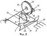
- фиг. 6 - механизм захвата.The proposed device for group stacking of products is illustrated by drawings, where on:
- FIG. 1 shows a device, front view;
- FIG. 2 - the same, top view;
- FIG. 3 - same, left view;
- FIG. 4 - same, right view;
- FIG. 5 - the same, rear view;
- FIG. 6 - capture mechanism.
Устройство содержит ротор 1, укрепленный на горизонтальном валу 2 с радиальными захватами 3, питатель 4 изделий, опору 5 для тары и привод 6. The device comprises a rotor 1 mounted on a
Каждый захват 3 жестко закреплен на конце ведомого (выходного) звена 7 кулачково-рычажного механизма (фиг. 6), другой конец которого шарнирно соединен с толкателем 8 ведущего кулачка 9, закрепленного на дополнительном валу 10, при этом ведомое звено в средней его части сопряжено с направляющей 11, закрепленной на оси 12, расположенной параллельно дополнительному валу и шарнирно соединенной с ротором, дополнительный вал 10 смонтирован в подшипниковых опорах, расположенных внутри ротора 1, на конце вала размещен фиксатор 13 для взаимодействия с тормозным диском 14 и шестерня 15 для взаимодействия с зубчатым сектором 16, при этом тормозной диск закреплен на опоре 17 (фиг. 3) вала 2 ротора 1, а зубчатый сектор 16 смонтирован на тормозном диске. Ведущий кулачок 9 выполнен в виде диска, имеющего со стороны его боковой поверхности замкнутый фигурный паз 18, имитирующий теоретический профиль, а толкатель 8 снабжен роликом для взаимодействия с пазом кулачка, при этом кулачок закреплен соосно относительно продольной оси дополнительного вала, а толкатель сопряжен с направляющей 19, жестко закрепленной на роторе, которая обеспечивает центральное расположение толкателя относительно центра вращения дополнительного вала. Each
Захват 3 выполнен вилкообразным и закреплен на стержне 20 (фиг. 6), который жестко связан с концом ведомого звена 7, выходящим за пределы ротора 1. Пальцы захвата 3 расположены относительно стержня 20 под прямым углом, взаимное расположение звена 7 и стержня 20 в пространстве таково, что пальцы в рабочем положении захвата направлены нормально к поверхности ротора 1. Такая компоновка ведомого звена, стержня и захвата обеспечивает возможность свободного прохода последнего в ящик при укладке изделий и бесконтактного выхода из ящика при движении относительно ротора. Рабочее положение захвата 3 определяется положением толкателя 8 при максимальном радиус-векторе профиля кулачка 9. The
Фиксатор 13 выполнен в виде тормозной колодки со сквозным отверстием для посадки на вал 10, причем колодка имеет фасонный вырез, радиус кривизны которого равен радиусу тормозного диска, а в теле колодки по периметру сквозного отверстия имеются сквозные пазы для шлицевых зубьев вала 10. На фиксаторе 13 со стороны его фасонного выреза смонтирован приводной ролик для взаимодействия с пазом 21 диска 14 (фиг. 6). Рабочая поверхность тормозного диска 14 имеет форму круглого цилиндра, паз 21 роликов фиксаторов выполнен в теле диска по его рабочей поверхности, профиль паза выполнен криволинейным, при этом один участок паза соответствует интервалу поворота вала 10 и захвата 3 на угол, равный 360o (т.е. интервалу движения захвата относительно ротора), а другой участок - интервалу движения захвата в рабочем положении. Первый участок паза 21 совмещен с зубчатым сектором 16, при этом зубчатый сектор крепится к тормозному диску 14 со стороны, противоположной ротору 1. Тормозной диск 14 имеет центральное отверстие, служащее для свободного прохода вала 2 ротора 1, и сквозные вырезы в виде дуг для крепления диска к опоре 17 с возможностью поворота его относительно оси вала 2 ротора при монтаже и наладке.The
Пальцы захватов 3 и стержни 20 выполнены трубчатыми из материала с малой массовой плотностью, при этом полости пальцев и стержня 20 каждого захвата сообщаются между собой. Пальцы захватов 3 снабжены вакуум-присосами 22, выполненными из эластичного материала. Полости пальцев через пустотелый стержень 20 посредством герметичной трубки, вала 2 ротора 21 и коллектора 23 связаны с источником вакуума, при этом трубка выполнена из вакуумной резины, закреплена скобками на концевой части ведомого звена 7 и образует петлю на участке между ведомым звеном и валом ротора. Подшипниковые опоры дополнительных валов 10 и осей 12 для направляющих 11 смонтированы на радиально расположенных спицах, жестко связанных с валом 2 ротора 1, при этом опоры имеют в основаниях продольные вырезы для болтов и крепятся к спицам с возможностью перемещения их в радиальном направлении. Этим обеспечивается регулировка расстояния между осями вала 2 ротора 1 и дополнительных валов 10, между осями 12 для направляющих 11 и осями дополнительных валов при наладке устройства. В цилиндрической стенке ротора 1 имеются сквозные вырезы 24, через которые проходят элементы захватов 3 при движении последних относительно ротора. Фиксаторы 13 и шестерни 15 закрыты защитным кожухом 25 цилиндрической формы, который днищем крепится к опоре 17. The fingers of the
Питатель 4 состоит из накопителя 26, формирователя 27 и ворошителя 28 изделий (фиг. 2). Накопитель 26 изделий выполнен в виде прямоугольного стола с полированной плоской рабочей поверхностью, укрепленного с наклоном в сторону формирователя 27 для изделий, при этом стол закреплен с возможностью регулирования его высоты при помощи винтовых муфт. Формирователь 17 ряда изделий выполнен в виде вилки, основание которой состыковано с накопителем 26 и закреплено на его раме. Каждый палец формирователя состоит из двух перпендикулярно расположенных одна относительно другой направляющих, горизонтальной и вертикальной, при этом рабочие поверхности горизонтальных направляющих всех пальцев формирователя расположены в одной плоскости, нормальной к поверхности ротора 1, а в теле горизонтальных направляющих имеются сквозные фигурные вырезы для прохода вакуум-присосов 22, смонтированных на пальцах захватов 3. Формирователь 27 закреплен с возможностью установки его в различных плоскостях, расположенных по нормали относительно ротора 1, для чего вилка выполнена поворотной относительно оси крепления ее на раме накопителя 26, а стыковка пальцев формирователя с накопителем изделий выполнена подвижной в направлении от накопителя к ротору, и наоборот. Каждая пара соседних пальцев формирователя 27 образует "ручей" для изделий. На концах пальцев формирователя укреплены фигурные упоры для изделий (по два на каждый "ручей"). Один из упоров в каждом "ручье" снабжен датчиком наличия изделий, при этом все датчики соединены последовательно и сблокированы системой автоматического управления с приводом 6 ротора 1 для подвода захватов 3 к формирователю 27 только при наличии в "ручьях" формирователя полного комплекта изделий. Для исключения остановки ротора 1 в период после захвата изделий вакуум-присосами 22 и снятия их с формирователя до окончания формирования нового ряда изделий предусмотрен конечный выключатель, вмонтированный в боковину паза 21 тормозного диска 14, нормально замкнутые контакты которого соединены параллельно с контактами датчиков наличия изделий. Над входной частью формирователя 27 перпендикулярно его пальцам установлена подпружиненная планка 29 (фиг. 2), служащая для предотвращения опрокидывания изделий, находящихся на накопителе, но контактирующих с крайними изделиями в "ручьях" формирователя, при подъеме комплекта изделий вакуум-присосами. Ворошитель 28 изделий состоит из двух параллельных реек, расположенных вдоль боковых кромок накопителя 26. Возвратно-поворотное движение реек ворошителя, воздействующих на изделия, облегчает вход последних в "ручьи" формирователя. Для обеспечения остановки ротора 1 при работающем электродвигателе привода 6 последний снабжен электромагнитной муфтой 30. The
Устройство работает следующим образом. The device operates as follows.
Включаются в работу ворошитель 28 и транспортер подачи изделий на накопитель 26, в позицию загрузки подается пустой ящик. После образования полного комплекта изделий на формирователе 27 включается в работу привод 6, обеспечивающий вращение ротора 1 с захватами 3. Пальцы захватов 3, проходя между пальцами формирователя 27, захватывают вакуум-присосами 22 изделия, находящиеся в "ручьях" формирователя, и переносят их в позицию загрузки. При вращении ротора 1 приводные ролики фиксаторов 13, перемещаясь в пазу 21 тормозного диска 14, перемещают фиксаторы, на которых они смонтированы, вдоль осей дополнительных валов 10. В позиции загрузки зубья шлицев дополнительного вала 10 выходят из зацепления со шлицами фиксатора 13, в результате чего последний перестает запирать захват 3 в рабочем положении. По окончании выхода шлицев из зацепления шестерня 15 входит в зацепление с зубчатым сектором 16, в вакуум-присосах 22 разрежение сменяется атмосферным давлением и изделия устанавливаются на дно ящика или на расположенный ниже ряд изделий, уже находящийся в ящике. The
Вал 10 продолжает поворачиваться вместе с ротором 1, при этом, поскольку шестерня 15 взаимодействует с зубчатым сектором 16, обеспечивается поворот на 360o укрепленного на валу 10 ведущего кулачка 9, который посредством толкателя 8 и направляющей 11 сообщает ведомому звену 7 сложное плоское движение относительно оси 12. В результате этого захват 3 выходит из ящика, перемещается от ящика к ротору 1, проходит мимо опоры 5, не имея контакта с последней, и до подхода к формирователю 27 возвращается в рабочее положение. После поворота кулачка 9 на 360o, что соответствует приходу захвата 3 в рабочее положение, шестерня 15 перестает взаимодействовать с зубчатым сектором 16, а шлицы фиксатора 13 входят в зацепление с зубьями шлицев вала 10, в результате чего захват 3 запирается в рабочем положении. При повороте кулачка 9 ведомое звено 7 совершает поворотное движение относительно направляющей 11, в результате чего захвату 3 сообщается движение по замкнутой плоской кривой.The
При подходе захвата 3 к формирователю 27 ролик фиксатора 13 нажимает на конечный выключатель, вмонтированный в паз 21 тормозного диска 14, и размыкает его контакт. Если формирователь 27 заполнен изделиями, ротор 1 продолжает вращение, если же ряд изделий не сформирован, ротор 1 посредством электромагнитной муфты 30 останавливается при работающем электродвигателе привода 6, по окончании формирования комплекта изделий на формирователе контакты датчиков наличия изделий замыкаются, и ротор 1 автоматически включается в работу. После загрузки ряда изделий в ящик опора 5 опускает ящик на расстояние, равное высоте изделия, а после наполнения ящика выводит его из устройства, сигнализируя о подаче под загрузку пустого ящика. В устройстве каждая ось 12 жестко связана с направляющей 11, взаимодействующей с ведомым звеном 7, и шарнирно связана с ротором 1. Возможна иная компоновка оси 12 с направляющей 11, при которой направляющая 11 шарнирно соединена с осью 12, а последняя жестко закреплена на роторе. When the
Выполнение кинематической связи захватов с валом ротора посредством кулачково-рчажных механизмов позволит исключить ударные нагрузки и таким образом повысить надежность функционирования устройства. В результате будут уменьшены внецикловые простои устройства, что повысит его производительность при достигнутой интенсификации процесса укладки изделий. The kinematic connection of the grippers with the rotor shaft by means of cam and lever mechanisms will eliminate shock loads and thus increase the reliability of the device. As a result, off-cycle downtime of the device will be reduced, which will increase its productivity with the achieved intensification of the product laying process.
Источники информации, принятые во внимание при составлении заявки
1. Авт. св. СССР N 501015, кл. B 65 B 5/10, 1973.Sources of information taken into account when preparing the application
1. Auth. St. USSR N 501015, class B 65
2. Авт. св. СССР N 1359200, кл. B 65 B 5/10, 1987. 2. Auth. St. USSR N 1359200, class B 65
Claims (3)
Translated fromRussianPriority Applications (1)
| Application Number | Priority Date | Filing Date | Title |
|---|---|---|---|
| RU96102270ARU2142391C1 (en) | 1996-02-07 | 1996-02-07 | Article group stowing device |
Applications Claiming Priority (1)
| Application Number | Priority Date | Filing Date | Title |
|---|---|---|---|
| RU96102270ARU2142391C1 (en) | 1996-02-07 | 1996-02-07 | Article group stowing device |
Publications (2)
| Publication Number | Publication Date |
|---|---|
| RU96102270A RU96102270A (en) | 1998-05-27 |
| RU2142391C1true RU2142391C1 (en) | 1999-12-10 |
Family
ID=20176594
Family Applications (1)
| Application Number | Title | Priority Date | Filing Date |
|---|---|---|---|
| RU96102270ARU2142391C1 (en) | 1996-02-07 | 1996-02-07 | Article group stowing device |
Country Status (1)
| Country | Link |
|---|---|
| RU (1) | RU2142391C1 (en) |
Cited By (3)
| Publication number | Priority date | Publication date | Assignee | Title |
|---|---|---|---|---|
| RU2220888C2 (en)* | 2001-08-13 | 2004-01-10 | Калининградский государственный технический университет | Device for group stacking of articles |
| RU2248313C1 (en)* | 2003-08-14 | 2005-03-20 | Калининградский государственный технический университет | Device for packing piece goods |
| RU2375271C1 (en)* | 2008-08-29 | 2009-12-10 | Федеральное государственное образовательное учреждение высшего профессионального образования "Калининградский государственный технический университет" | Device for layered packing of piece items |
- 1996
- 1996-02-07RURU96102270Apatent/RU2142391C1/enactive
Cited By (3)
| Publication number | Priority date | Publication date | Assignee | Title |
|---|---|---|---|---|
| RU2220888C2 (en)* | 2001-08-13 | 2004-01-10 | Калининградский государственный технический университет | Device for group stacking of articles |
| RU2248313C1 (en)* | 2003-08-14 | 2005-03-20 | Калининградский государственный технический университет | Device for packing piece goods |
| RU2375271C1 (en)* | 2008-08-29 | 2009-12-10 | Федеральное государственное образовательное учреждение высшего профессионального образования "Калининградский государственный технический университет" | Device for layered packing of piece items |
Similar Documents
| Publication | Publication Date | Title |
|---|---|---|
| JP2527867B2 (en) | Boxing or unpacking device for containers | |
| EP2998232B1 (en) | Device for transporting flexible containers held suspended in a packaging line | |
| NL1006370C2 (en) | Conveyor for accelerating a range of products. | |
| KR101456294B1 (en) | A reciprocating forward-feed device for the clocked linear forward-feed of stacks of goods over a transport path | |
| EP2998229B1 (en) | Transportation method for flexible containers held suspended in a packaging line, device capable of putting the method into practice and machine comprising said device | |
| JP2011518739A (en) | Method and arrangement for transferring a packaging container from a first unit to a second unit | |
| US5313764A (en) | Packing apparatus | |
| AU729300B2 (en) | Carton feed opening wheel assembly | |
| US10549924B2 (en) | Robotic article collation and metering assembly | |
| RU2142391C1 (en) | Article group stowing device | |
| AU712282B2 (en) | Automatic dual pocket loader wheel assembly | |
| CA1042030A (en) | Method and apparatus for transferring cans | |
| CN115384859A (en) | Automatic box packing line | |
| EP0510953B1 (en) | Cam assembly and feeder mechanism for use in a packaging machine | |
| EP1479607A1 (en) | Automatic packaging machine | |
| US5046602A (en) | Inertial conveyor system | |
| RU2143384C1 (en) | Piece goods stowing device | |
| CN1030519A (en) | Pass on the device of tobacco industry block elements group | |
| EP0687629B1 (en) | Machine for packaging fragile cylindrical products, particularly cigarettes | |
| RU2146213C1 (en) | Device for layer-by-layer stowing piece articles | |
| RU2091277C1 (en) | Device for placing groups of articles into containers | |
| RU2091276C1 (en) | Device for placing articles into containers and on pallets | |
| RU2151087C1 (en) | Device for layer-by-layer storing of piece articles | |
| RU2137686C1 (en) | Article stowing device | |
| RU2142392C1 (en) | Device for stowing articles in container |