RU2138622C1 - Method and device for operation of well - Google Patents
Method and device for operation of wellDownload PDFInfo
- Publication number
- RU2138622C1 RU2138622C1RU97116568ARU97116568ARU2138622C1RU 2138622 C1RU2138622 C1RU 2138622C1RU 97116568 ARU97116568 ARU 97116568ARU 97116568 ARU97116568 ARU 97116568ARU 2138622 C1RU2138622 C1RU 2138622C1
- Authority
- RU
- Russia
- Prior art keywords
- auxiliary pipe
- cavity
- medium
- well
- pipe
- Prior art date
Links
- 238000000034methodMethods0.000titleclaimsabstractdescription24
- 239000012530fluidSubstances0.000claimsabstractdescription38
- 238000004519manufacturing processMethods0.000claimsabstractdescription35
- 238000010438heat treatmentMethods0.000claimsabstractdescription13
- 238000005086pumpingMethods0.000claimsabstract2
- 238000005065miningMethods0.000claimsdescription19
- 238000009434installationMethods0.000claimsdescription18
- 230000015572biosynthetic processEffects0.000claimsdescription16
- 238000002347injectionMethods0.000claimsdescription10
- 239000007924injectionSubstances0.000claimsdescription10
- 238000007789sealingMethods0.000claimsdescription8
- 239000011435rockSubstances0.000claimsdescription7
- 238000002955isolationMethods0.000claimsdescription6
- 210000002445nippleAnatomy0.000claimsdescription5
- 239000003989dielectric materialSubstances0.000claimsdescription4
- 230000003247decreasing effectEffects0.000claimsdescription3
- 230000008021depositionEffects0.000claims1
- 239000000126substanceSubstances0.000abstractdescription4
- 230000000694effectsEffects0.000abstractdescription3
- 230000002035prolonged effectEffects0.000abstract1
- 238000011084recoveryMethods0.000abstract1
- 230000008439repair processEffects0.000abstract1
- 238000007669thermal treatmentMethods0.000abstract1
- 239000002609mediumSubstances0.000description47
- 239000007789gasSubstances0.000description11
- 230000006378damageEffects0.000description4
- 150000004677hydratesChemical class0.000description4
- XLYOFNOQVPJJNP-UHFFFAOYSA-NwaterSubstancesOXLYOFNOQVPJJNP-UHFFFAOYSA-N0.000description4
- 239000002826coolantSubstances0.000description3
- 239000007788liquidSubstances0.000description3
- 239000003921oilSubstances0.000description3
- 229920005989resinPolymers0.000description3
- 239000011347resinSubstances0.000description3
- IJGRMHOSHXDMSA-UHFFFAOYSA-NAtomic nitrogenChemical compoundN#NIJGRMHOSHXDMSA-UHFFFAOYSA-N0.000description2
- LYCAIKOWRPUZTN-UHFFFAOYSA-NEthylene glycolChemical compoundOCCOLYCAIKOWRPUZTN-UHFFFAOYSA-N0.000description2
- 230000007423decreaseEffects0.000description2
- 238000005516engineering processMethods0.000description2
- 238000000605extractionMethods0.000description2
- 239000003112inhibitorSubstances0.000description2
- 241000208202LinaceaeSpecies0.000description1
- 235000004431Linum usitatissimumNutrition0.000description1
- DIWRORZWFLOCLC-UHFFFAOYSA-NLorazepamChemical compoundC12=CC(Cl)=CC=C2NC(=O)C(O)N=C1C1=CC=CC=C1ClDIWRORZWFLOCLC-UHFFFAOYSA-N0.000description1
- 239000005662Paraffin oilSubstances0.000description1
- 230000002730additional effectEffects0.000description1
- 239000010426asphaltSubstances0.000description1
- 239000013043chemical agentSubstances0.000description1
- 230000005611electricityEffects0.000description1
- 239000012526feed mediumSubstances0.000description1
- 229930195733hydrocarbonNatural products0.000description1
- 150000002430hydrocarbonsChemical class0.000description1
- WGCNASOHLSPBMP-UHFFFAOYSA-NhydroxyacetaldehydeNatural productsOCC=OWGCNASOHLSPBMP-UHFFFAOYSA-N0.000description1
- 229910052757nitrogenInorganic materials0.000description1
- 239000012188paraffin waxSubstances0.000description1
- 230000008092positive effectEffects0.000description1
- 238000002360preparation methodMethods0.000description1
- 230000002265preventionEffects0.000description1
- 239000000243solutionSubstances0.000description1
Images


Landscapes
- Physical Or Chemical Processes And Apparatus (AREA)
Abstract
Description
Translated fromRussianИзобретение относится к области добычи нефти, газа и газоконденсата и может быть использовано при эксплуатации скважин с тепловым воздействием на добываемый флюид, в частности, для исключения образования отложений в добывающем подъемнике, например, гидратов, парафинов, смол и асфальтов, а также для снижения вязкости и потерь тепла флюида в добывающем подъемнике и призабойной зоне скважины. The invention relates to the field of oil, gas and gas condensate production and can be used in the operation of wells with thermal effects on the produced fluid, in particular, to prevent the formation of deposits in the production lift, for example, hydrates, paraffins, resins and asphalts, as well as to reduce viscosity and fluid heat loss in a production lift and a well bottom zone.
Известен способ предотвращения отложений гидратов в скважине (авт. cв. N 827753, E 21 B 43/00, 1981 г.), включающий подачу на забой скважины ингибитора гидратообразования. A known method of preventing hydrate deposits in a well (ed. St. N 827753, E 21
Известен способ теплового разрушения гидратной пробки в скважине (патент СССР N 1796010, E 21 B 37/06, 1993 г.), включающий спуск в добывающий подъемник вспомогательной трубы с обратным клапаном и гидромониторным наконечником, подготовку и нагрев рабочей среды на устье скважины, нагнетание ее во вспомогательную трубу и отведение продуктов разрушения через узлы дросселирования в отвод добывающего подъемника на устье. Недостатком способа является то, что он имеет узкую область применения, в том числе не предусматривает предотвращения образования гидратов, парафинов, смол, асфальтов и прочих отложений в процессе эксплуатации скважины, т.е. данный способ применяется уже после образования отложений в добывающем подъемнике. A known method of thermal destruction of hydrate plugs in a well (USSR patent N 1796010, E 21
Известно устройство для предупреждения парафиногидратообразований в скважинных трубах (авт. св. 1839043, E 21 B 37/00, 36/04, 1990 г.), включающее спущенный в добывающий подъемник электронагреватель с подключенным к нему кабелем, связанным со станцией управления. Недостатком устройства является то, что оно имеет низкий коэффициент теплопередачи, так как электронагреватель имеет небольшую теплообменную площадь, которая постоянно контактирует с потоком добывающего флюида, и не успевает нагревать ее до оптимальной температуры. A device is known for preventing paraffin hydrate formation in downhole pipes (ed. St. 1839043, E 21
Известно устройство для эксплуатации скважины, добывающей высокопарафинистую нефть (авт. cв. 1252479, E 21 B 43/00, 1986 г.), в качестве наиболее близкого аналога, содержащее подогреватель, эксплуатационную колонну, насосно-компрессорные трубы, разделитель и дополнительную колонну труб с открытым нижним концом, установленную параллельно насосно-компрессорным трубам. Это устройство имеет низкую эффективность, т.к. затрубное пространство полностью заполнено жидкостью (теплопроводность жидкости значительно больше, чем теплопроводность газа), из-за чего увеличивается потеря тепла в сторону горных пород. Также оно сложно реализуемо для механизированного способа добычи нефти из скважин, поскольку требуются для известной технологии специальный разобщитель (пакер) и устьевые оборудования для спуска дополнительно колонны труб с электрообогревателями между эксплуатационной и основной колонной труб. A device is known for operating a well producing high-paraffin oil (ed. St. 1252479, E 21
Целью изобретения является повышение эффективности работы скважин при различных способах эксплуатации. The aim of the invention is to increase the efficiency of wells with various methods of operation.
Положительный эффект от использования изобретения заключается в повышении производительности скважин, уменьшении межремонтного периода и повышении надежности работы скважинного оборудования. The positive effect of the use of the invention is to increase well productivity, reduce the overhaul period and increase the reliability of downhole equipment.
Поставленная цель достигается за счет следующих технологических решений. The goal is achieved through the following technological solutions.
Полость вспомогательной трубы разобщают или сообщают гидравлически с полостью добывающего подъемника, при этом полость вспомогательной трубы заполняют полностью или частично средой с высокой теплопроводностью (водой, гликолем, маслом и др. ) для нагревания или с низкой теплопроводностью (воздухом, паром, азотом, углеводородами и др.) для снижения потерь тепла добываемого флюида, причем используют вспомогательную трубу постоянного или переменного сечения и концентрично или эксцентрично спускают внутрь и/или снаружи добывающего подъемника. The cavity of the auxiliary pipe is disconnected or hydraulically connected with the cavity of the mining elevator, while the cavity of the auxiliary pipe is completely or partially filled with medium with high thermal conductivity (water, glycol, oil, etc.) for heating or with low thermal conductivity (air, steam, nitrogen, hydrocarbons and etc.) to reduce the heat loss of the produced fluid, using an auxiliary pipe of constant or variable cross section and concentrically or eccentrically lowered inside and / or outside the producing hoist ka.
Спускают в скважину вспомогательную трубу с герметично изолированным нижним концом и одновременно заполняют ее полость средой с высокой теплопроводностью или полость вспомогательной трубы заполняют средой после завершения спуска вспомогательную трубу в скважину и затем герметично изолируют ее нижний конец. Спускают один или несколько электронагревателей в вспомогательную трубу (например, на кабеле) и нагревают среду с высокой теплопроводностью непосредственно в полости вспомогательной трубы (на соответствующих глубинах) до температуры - выше температуры образования отложений (гидратов, парафинов, смол, асфальтов и др.) или до температуры уменьшения вязкости добываемого флюида. Вспомогательная труба может быть оснащена одним или несколькими нагнетательными устройствами, при этом полость вспомогательной трубы над средой с высокой теплопроводностью дополнительно заполняют рабочей средой (однородной или неоднородной) для нагнетания ее в полость добывающего подъемника (в качестве рабочей среды могут быть использованы химреагенты, газ, нефть и т. д.). Измеряют значение давления и/или температуры добываемого флюида, и в случае их отклонения (в сторону уменьшения) от давления и/или температуры - выше температуры образования отложения, нагнетают (постоянно или периодически) рабочую среду в добывающий подъемник для предотвращения возможности образования отложений. The auxiliary pipe is lowered into the well with a hermetically insulated lower end and at the same time its cavity is filled with a medium with high thermal conductivity or the cavity of the auxiliary pipe is filled with medium after completion of the descent of the auxiliary pipe into the well and then its lower end is hermetically isolated. One or more electric heaters are lowered into an auxiliary pipe (for example, on a cable) and a medium with high thermal conductivity is heated directly in the cavity of the auxiliary pipe (at appropriate depths) to a temperature above the temperature of formation of deposits (hydrates, paraffins, resins, asphalts, etc.) or to a temperature of decreasing the viscosity of the produced fluid. The auxiliary pipe can be equipped with one or several discharge devices, while the cavity of the auxiliary pipe above the medium with high thermal conductivity is additionally filled with a working medium (homogeneous or inhomogeneous) to pump it into the cavity of the production lift (chemicals, gas, oil can be used as a working medium etc.). The pressure and / or temperature of the produced fluid is measured, and if they deviate (in the direction of decrease) from the pressure and / or temperature above the temperature of the formation of deposits, the working medium is pumped (continuously or periodically) into the production lift to prevent the possibility of formation of deposits.
Внутрь или снаружи вспомогательной трубы может быть спущена дополнительная труба, а в полость, образованную между ними, подают (постоянно или периодически) нагретую среду. В качестве подаваемой среды может быть использован флюид, добываемый из соседней скважины для использования его тепла. Вспомогательная труба может быть дополнительно оснащена на уровне или под уровнем продуктивного пласта элементом теплопередачи, а ниже - наружным разобщителем, причем продукцию пласта, расположенного ниже продуктивного, направляют (через нагнетательное или концевое устройство) в полость вспомогательной трубы, что обеспечивает использование ее в качестве теплоносителя. Предварительно нагревают среду с высокой теплопроводностью в полости вспомогательной трубы и подают (постоянно или периодически) в зону продуктивного пласта для снижения вязкости флюида до заданного значения. Вспомогательную трубу и добывающий подъемник спускают ниже продуктивного пласта в зону повышенной геотермической температуры, а добываемый флюид направляют в добывающий подъемник через вспомогательную трубу, тем самым добываемый флюид нагревают теплом горной породы. An additional pipe may be lowered inside or outside the auxiliary pipe, and a heated medium is supplied (continuously or periodically) to the cavity formed between them. A fluid produced from a neighboring well to use its heat can be used as the feed medium. The auxiliary pipe can be additionally equipped with a heat transfer element at or below the level of the reservoir, and an external disconnector below, and the products of the reservoir below the reservoir are directed (through the injection or end device) into the cavity of the auxiliary pipe, which ensures its use as a coolant . Preheat the medium with high thermal conductivity in the cavity of the auxiliary pipe and feed it (continuously or periodically) into the zone of the reservoir to reduce the viscosity of the fluid to a predetermined value. The auxiliary pipe and the production lift are lowered below the reservoir into the zone of elevated geothermal temperature, and the produced fluid is sent to the production lift through the auxiliary pipe, thereby producing the produced fluid heated by rock heat.
Установка дня эксплуатации скважины включает спущенные в скважину вспомогательную трубу и добывающий подъемник и установленные внутри или снаружи вспомогательной трубы электронагреватели, связанные через кабель со станцией управления. С целью повышения эффективности работы установки вспомогательная труба постоянного или переменного сечения установлена внутри или/и снаружи добывающего подъемника и оснащена концевым изолирующим, и/или одним или несколькими нагнетательными устройствами, что позволяет целенаправленно разобщать или соединять полость вспомогательной трубы с полостью добывающего подъемника и/или нагнетать в нее рабочую среду (это позволяет нагревать среду с высокой теплопроводностью непосредственно в полости вспомогательной трубы и передачи ее тепла добываемому флюиду). Нагнетательное устройство вспомогательной трубы может быть выполнено в виде скважинной овальной камеры с посадочным гнездом, в котором установлен съемный клапан, включающий полый корпус с каналами, уплотнениями и фиксатором, внутри корпуса размещен заряженный сжатым газом сильфон, с одной стороны жестко связанный с корпусом, а с другой - со штоком запорного элемента "затвор-седло", что обеспечивает нагнетание рабочей среды в полость добывающего подъемника при заданном избыточном давлении, а также позволяет при необходимости заменять клапан на глухую пробку с помощью канатной техники. Установка также может быть оснащена наружным разобщителем, а концевое изолирующее устройство выполнено в виде корпуса, внутри которого установлен полый поршень, причем корпус с одной стороны соединен с концом вспомогательной трубы, а с другой - с наружным разобщителем, при этом полый поршень жестко связан с добывающим подъемником. Концевое изолирующее устройство вспомогательной трубы может быть выполнено в виде корпуса с осевым несквозным и поперечными каналами, внутри которого установлена уплотняющая пробка, связанная с корпусом срезными элементами (винтами, штифтами), причем при срезанном положении уплотняющей пробки полость вспомогательной трубы гидравлически соединена с поперечными каналами корпуса. Концевое изолирующее устройство вспомогательной трубы также может быть выполнено в виде либо заглушки, либо установленных в ниппеле съемной глухой пробки или работающего от избыточного давления клапана с уплотнениями и фиксатором, причем в корпусе клапана размещен заряженный сильфон, с одной стороны жестко связанный с корпусом, а с другой - со штоком запорного элемента "затвор-седло". Кроме того, концевое изолирующее устройство может быть выполнено в виде корпуса, внутри которого установлен уплотняющий неподвижный или подвижный поршень, причем корпус соединен с концом вспомогательной трубы, а поршень жестко связан с добывающим подъемником или штангой глубинного насоса. Вспомогательная труба нижним заглушенным концом может быть жестко соединена со штангой или плунжером насоса, а сверху - с полированным полым штоком. Электронагреватель может быть установлен снаружи добывающего подъемника и связан через питающий кабель с погружным электродвигателем центробежного насоса, что позволяет одновременно обеспечивать нагревание флюида и работу центробежного насоса. Внутри или снаружи вспомогательной трубы может быть установлена дополнительная труба для заполнения образующейся полости средой с низкой или высокой теплопроводностью, или для создания циркуляции нагретой среды. Вспомогательная труба установлена ниже продуктивного пласта в зоне повышенной геотермической температуры горных пород, чтобы использовать тепло горных пород для нагревания добываемого флюида. Также вспомогательная или дополнительная трубы могут быть соединены с кабелем и оснащены одним или несколькими диэлектриками и центраторами в скважине для использования их в качестве электронагревателя. The installation of the day of operation of the well includes an auxiliary pipe lowered into the well and a production elevator and electric heaters installed inside or outside the auxiliary pipe connected through a cable to the control station. In order to increase the efficiency of the installation, an auxiliary pipe of constant or variable cross-section is installed inside and / or outside the production lift and is equipped with an end isolating and / or one or more discharge devices, which allows you to deliberately disconnect or connect the cavity of the auxiliary pipe with the cavity of the production lift and / or pump the working medium into it (this allows you to heat the medium with high thermal conductivity directly in the cavity of the auxiliary pipe and transfer its heat produced fluid). The auxiliary pipe injection device can be made in the form of an oval borehole chamber with a seat, in which a removable valve is installed, including a hollow body with channels, seals and a clamp, a bellows charged with compressed gas is placed inside the housing, on one side it is rigidly connected to the housing, and the other with a shutter-saddle locking element stock, which ensures the injection of the working medium into the cavity of the production lift at a given overpressure, and also allows to replace cells if necessary upan on a dead stopper using cable technology. The installation can also be equipped with an external disconnector, and the end isolation device is made in the form of a housing inside which a hollow piston is installed, the housing being connected to the end of the auxiliary pipe on one side and the external disconnector on the other, while the hollow piston is rigidly connected to the producing lift. The end insulating device of the auxiliary pipe can be made in the form of a housing with axial non-through and transverse channels, inside of which there is a sealing plug connected to the housing by shear elements (screws, pins), and when the sealing plug is cut off, the cavity of the auxiliary pipe is hydraulically connected to the transverse channels of the housing . The end insulating device of the auxiliary pipe can also be in the form of either a plug or a removable blind plug installed in the nipple or of an overpressure valve with seals and a clamp; moreover, a charged bellows is placed in the valve body, which is rigidly connected to the body on one side, and the other with a stem of the shutter-saddle locking element. In addition, the end insulating device can be made in the form of a housing, inside of which a sealing fixed or movable piston is installed, the housing being connected to the end of the auxiliary pipe, and the piston is rigidly connected to the producing lift or rod of the downhole pump. The auxiliary pipe with the lower muffled end can be rigidly connected to the rod or plunger of the pump, and on top with a polished hollow rod. An electric heater can be installed outside the production lift and connected through a power cable to a submersible electric motor of a centrifugal pump, which allows for simultaneous heating of the fluid and the operation of the centrifugal pump. An additional pipe may be installed inside or outside the auxiliary pipe to fill the resulting cavity with a medium with low or high thermal conductivity, or to create a circulation of the heated medium. The auxiliary pipe is installed below the reservoir in the zone of increased geothermal temperature of rocks in order to use the heat of rocks to heat the produced fluid. Also, the auxiliary or additional pipes can be connected to the cable and equipped with one or more dielectrics and centralizers in the well for use as an electric heater.
Способ включает спуск добывающего подъемника и вспомогательной трубы в скважину, подачу среды в полость вспомогательной трубы, заполнение полости вспомогательной трубы и полости за добывающим подъемником средой для нагревания и добычу флюида из продуктивного пласта. Данный способ реализуется с помощью установки. The method includes lowering the production elevator and the auxiliary pipe into the well, supplying the medium to the cavity of the auxiliary pipe, filling the cavity of the auxiliary pipe and the cavity behind the producing elevator with heating medium and producing fluid from the reservoir. This method is implemented using the installation.
На фиг. 1-16 приводятся различные варианты установки для реализации способа. In FIG. 1-16 are various installation options for implementing the method.
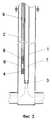
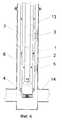
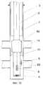
Установка (фиг. 1) включает добывающий (газлифтный, фонтанный или насосный) подъемник 1 и вспомогательную трубу 2, спущенные в скважину 3. Вспомогательная труба 2 (постоянного или переменного сечения) установлена внутри (фиг. 1) или(и) снаружи (фиг. 2) добывающего подъемника 1 (в зависимости от условий эксплуатации скважины) и оснащена концевым изолирующим устройством 4. Вспомогательная труба 2 может быть оснащена одним или несколькими нагнетательными устройствами 5. При этом возможно целенаправленно разобщать и(или) соединять полость 6 вспомогательной трубы 2 с полостью 7 добывающего подъемника 1 и(или) нагнетать рабочую среду в полость 7 добывающего подъемника 1. Вспомогательную трубу 2 спускают в скважину 3 концентрично (фиг. 1, 2) или эксцентрично (фиг. 3) в зависимости от конструкции и условий эксплуатации скважины. The installation (Fig. 1) includes a production (gas-lift, fountain or pump)
Вспомогательная труба 2 может быть снабжена одним или несколькими электронагревателями 8, связанными через кабель 9 со станцией управления 10 для нагревания среды с высокой теплопроводностью, например, непосредственно в полости 6 вспомогательной трубы 2. Добывающий подъемник 1 может быть оснащен наружным разобщителем 11 и нагнетательным устройством 5 для заполнения полости 12 средой с высокой или(и) низкой теплопроводностью. Снаружи (фиг. 1) или(и) внутри (фиг. 4) вспомогательной трубы 2 может быть установлена дополнительная труба 13. В ряде случаев дополнительная труба 13 может быть оснащена наружным разобщителем 11 и нагнетательным устройством 5. Призабойная зона скважины 3 гидравлически связана с продуктивным пластом 14. The
Нагнетательное устройство (фиг. 5) вспомогательной трубы 2 может быть выполнено в виде скважинной овальной камеры 15 с посадочным гнездом 16, в котором установлен съемный клапан, включающий полый корпус 17 с каналами 18, уплотнениями 19 и фиксатором 20. Внутри корпуса 17 размещен заряженный сжатым газом сильфон 21, с одной стороны жестко связанный с корпусом 17, а с другой - со штоком 22 запорного элемента, выполненного в виде затвора 23 и седла 24. Скважинная овальная камера 15 может иметь наружные 25 или внутренние 26 поперечные и продольные 27 каналы. При наличии каналов 26 и 27 нижний конец посадочного гнезда 16 герметично изолирован от полости камеры 15. The injection device (Fig. 5) of the
Концевое изолирующее устройство может быть выполнено в виде корпуса 28 (фиг. 6), внутри которого установлен полый поршень 29, причем корпус 28 с одной стороны соединен с концом вспомогательной трубы 2, а с другой - с наружным разобщителем 11, при этом полый поршень 29 жестко связан с добывающим подъемником 1. Последний может быть оснащен газлифтными клапанами 30 или(и) глубинным насосом 31, или фонтанным оборудованием. Причем газлифтные клапаны 30 и нагнетательные устройства 5 могут быть выполнены аналогично. The end insulating device can be made in the form of a housing 28 (Fig. 6), inside of which a
В качестве подаваемой в скважину 3 среды может быть использован флюид, добываемый из соседней скважины 32. As the medium supplied to the
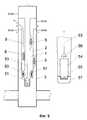
Концевое изолирующее устройство (фиг. 7) вспомогательной трубы 2 может быть выполнено в виде корпуса 33 с осевым несквозным 34 и поперечными 35 каналами, внутри которого установлена уплотняющая пробка 36, связанная с корпусом 33 срезными элементами 37. Причем при срезанном положении уплотняющей пробки 36 полость 6 вспомогательной трубы 2 гидравлически соединяется с поперечными каналами 35 (фиг. 7, В. 1). Концевое изолирующее устройство вспомогательной трубы 2 также может быть выполнено в виде заглушки 38 (фиг. 7, В. 2). Кроме того, оно может быть выполнено в виде установленных в ниппеле 39 съемной глухой пробки 40 (фиг. 7, В. 3) или клапана (фиг. 8). Съемный клапан также может быть выполнен в виде корпуса 41 с уплотнениями 42 и фиксатором 43, причем в корпусе 41 размещен заряженный сильфон 44, с одной стороны жестко связанный с корпусом 41, а с другой - со штоком 45 запорного элемента в виде затвора 46 и седла 47. При этом ниппель 39 выполнен в виде полого цилиндра с осевым продольным каналом 48. Ниппель 39 также может иметь поперечные каналы 49. The end insulating device (Fig. 7) of the
Концевое изолирующее устройство может быть выполнено в виде корпуса 50, внутри которого установлен уплотняющий неподвижный 51 (фиг. 9) или подвижный 52 (фиг. 10) поршень, причем корпус 50 соединен с концом вспомогательной трубы 2, а поршень 51 или 52 жестко связан с добывающим подъемником 1 или штангой 53 глубинного насоса 31. Глубинный насос 31 может быть выполнен в виде сильфона 54 с нижним 55 и верхним 56 клапанами. Сильфон 54 жестко связан нижним концом с цилиндром 57, а верхним концом - со штангой 53 (фиг. 9). Кроме того, полость 6 вспомогательной трубы 2 может быть гидравлически соединена с емкостью 58 рабочей среды через обратный клапан 59 (фиг. 10). The end insulating device can be made in the form of a
Вспомогательная труба 2 (фиг. 11) нижним заглушенным концом 4 может быть жестко соединена со штангой 53 или плунжером насоса 31, а сверху - с полированным полым штоком 60. The auxiliary pipe 2 (Fig. 11) with the
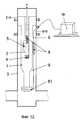
Электронагреватель 8 (фиг. 12) может быть установлен снаружи добывающего подъемника 1 и связан через питающий кабель 9, с одной стороны, со станцией управления 10, а с другой, - с погружным электродвигателем центробежного насоса 61. An electric heater 8 (Fig. 12) can be installed outside the
Вспомогательная труба 2 может быть дополнительно оснащена (фиг. 13) на уровне или под уровнем продуктивного пласта 14 элементом теплопередачи 62, а ниже - наружным разобщителем 11 для возможности использования в качестве среды с высокой теплопроводностью продукции пласта 63, расположенного ниже продуктивного пласта 14. The
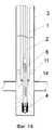
Вспомогательная труба 2 (фиг. 14) может быть спущена ниже продуктивного пласта 14 с концевым изолирующим устройством 4 в виде клапана (фиг. 8). The auxiliary pipe 2 (Fig. 14) can be lowered below the
Вспомогательная труба 2 (фиг. 15) может быть установлена ниже продуктивного пласта 14 с заглушенным концом 4 в зоне повышенной геотермической температуры горных пород. При этом добывающий подъемник 1 спускают ниже продуктивного пласта 14, причем добывающий подъемник 1 может быть оснащен наружным разобщителем 11 и(или) газлифтными клапанами 30, или насосом 31, или фонтанным оборудованием. The auxiliary pipe 2 (Fig. 15) can be installed below the
Вспомогательная 2 или(и) дополнительная 13 трубы (фиг. 16) могут быть соединены с кабелем 9 и оснащены одним или несколькими диэлектриками 64 и центраторами 65 внутри скважины 3, что позволяет использовать их в качестве электронагревателя. При этом кабель(и) 9 спускают внутри или снаружи труб 2 или 13 и соединяют их через контактные элементы 66. Auxiliary 2 or (and) additional 13 pipes (Fig. 16) can be connected to
При реализации способа установка работает следующим образом. When implementing the method, the installation works as follows.
Полость 6 вспомогательной трубы 2 (фиг. 1-3, 6, 9-15) заполняют средой с высокой теплопроводностью. Например, создают избыточное давление в полости 6, открывают нагнетательное 5 или концевое изолирующее 4 устройства, через которое выдавливают жидкость из вспомогательной трубы 2 путем заполнения полости 6 средой с высокой теплопроводностью. Затем снимают избыточное давление в вспомогательной трубе 2 и разобщают полость 6 от полости 7 добывающего подъемника 1, после чего от станции управления 10 через кабель 9 подают напряжение на электронагреватель 8, посредством чего нагревают среду до заданной температуры. При этом добываемый флюид из продуктивного пласта 14 поступает в полость 7 и входит в контакт с наружной или внутренней поверхностью вспомогательной трубы 2, в результате чего происходит нагревание флюида, что предотвращает возможность образования отложений, например, парафинов, гидратов и др. в процессе эксплуатации 3. Также в добываемый подъемник 1 может быть нагнетена рабочая среда (химреагент, газ, нефть, пар и т. д.) из вспомогательной трубы 2 через нагнетательное устройство 5 с целью получения дополнительного эффекта для предотвращения образования отложений, например, за счет разрушения их структуры химреагентом, изменения давления потока флюида или дополнительного подогрева рабочей средой. Кроме того, в полость 7 непрерывно или периодически может нагнетаться неоднородная среда в зависимости от эксплуатации скважины 3. Например, через нижнее нагнетательное устройство 5 подается химреагент, а через верхнее - газ. The
В зависимости от характера эксплуатации скважины 3 полость 12, образующаяся между добывающим подъемником 1 или дополнительной трубой 13 и скважиной 3 (фиг. 1), может быть заполнена средой с низкой теплопроводностью для снижения потерь тепла добываемого флюида (например, на глубине вечной мерзлоты) или средой с высокой теплопроводностью для передачи дополнительного тепла флюиду, а также для создания циркуляции рабочей среды через нагнетательное устройство 5. Следует отметить, что при подаче рабочей среды (нефти) в полость 7 добывающего подъемника 1 давление в ней растет, причем этот прирост давления уменьшает вероятность образования отложений, например, гидрата. С целью исключения возможности повреждения (смятия) ствола (обсадной колонны) скважины 3, средой с низкой теплопроводностью следует заполнять полость 6 вспомогательной трубы 2 (фиг. 2, 6,9), которая спущена снаружи добывающего подъемника 1. Depending on the nature of the operation of the
В полость 6 (фиг. 4) вспомогательной трубы 2 может быть подана нагретая среда и обеспечена циркуляция среды через полость дополнительной трубы 13. При этом тепло нагретой среды через поверхность вспомогательной трубы 2 передается добываемому флюиду. Heated medium can be supplied into the cavity 6 (Fig. 4) of the
Нагнетательное устройство (фиг. 5) вспомогательной или дополнительной труб или добывающего подъемника функционирует следующим образом. В случае подачи среды в полость вспомогательной трубы 2, избыточное давление через каналы 26 посадочного гнезда 16 и верхние каналы 18 корпуса 17 действует на площадь заряженного сильфона 21 и открывает затвор 23, таким образом среда поступает через нижние каналы 18 корпуса 17 и канал 27 камеры 15 в полость добывающего подъемника (каналы 25 отсутствуют). При снятии избыточного давления затвор 23, перемещаясь, закрывает проходное сечение седла 24. А в случае подачи среды в полость добывающего подъемника или дополнительной трубы, избыточное давление через каналы 25 камеры 15 и верхние каналы 18 корпуса 17 также действует на площадь заряженного сильфона 21 и открывает затвор 23, таким образом среда поступает в полость 6 вспомогательной трубы 2 через нижние каналы 18 корпуса 17 (каналы 26 и 27 отсутствуют). The discharge device (Fig. 5) auxiliary or additional pipes or mining hoist operates as follows. If the medium is supplied into the cavity of the
Концевое изолирующее устройство в виде клапана (фиг. 8) работает от избыточного давления в вспомогательной трубе 2. В случае необходимости сообщения полостей вспомогательной трубы 2 и добывающего подъемника 1 создают избыточное давление среды в вспомогательной трубе, тем самым воздействуют на площадь заряженного сильфона 44 и открывают затвор 46. An end isolation device in the form of a valve (Fig. 8) works from excessive pressure in the
Если полость 6 (фиг. 10) вспомогательной трубы 2 гидравлически связана с рабочей емкостью 58, то при ходе плунжера насоса 31 вверх давление в полости 6 растет за счет перемещения поршня 52, при этом нагнетательное устройство 5 открывается и через него рабочая среда (например, ингибитор) поступает в полость 7 добывающего подъемника 1. А при ходе плунжера вниз давление в полости 6 падает и тем самым рабочая среда из емкости 58 поступает в полость 6. If the cavity 6 (Fig. 10) of the
Продукция (вода, нефть и т.д.) пласта 63, расположенного ниже продуктивного 14 (фиг. 13), может быть направлена в полость 6 вспомогательной трубы 2, в результате чего нагревают добываемый флюид в призабойной зоне скважины 3 и добывающем подъемнике 1 через элемент теплопередачи 62 и поверхность вспомогательной трубы 2. The products (water, oil, etc.) of the
При необходимости теплового воздействия на призабойную зону пласта 14 (фиг. 14) создают требуемое избыточное давление в вспомогательной трубе 2 и открывают клапан концевого изолирующего устройства 4, через который непрерывно или периодически подают нагретую среду на забой скважины 3, тем самым нагревают добываемый флюид (например, с высокой вязкостью) в призабойной зоне скважины 3. If thermal influence is necessary on the bottom-hole zone of the formation 14 (Fig. 14), the required overpressure is created in the
Флюид из продуктивного пласта 14 (фиг. 15) может быть направлен в полость 7 добывающего подъемника 1 через вспомогательные трубы 2, расположенные ниже пласта 14 в зоне повышенной геотермической температуры горной породы. При этом флюид, проходя через полость 6 вспомогательной трубы 2, нагревается, что снижает вероятность образования отложений в добывающем подъемнике 1, а в случае высокой вязкости добываемого флюида снижает значение последней. The fluid from the reservoir 14 (Fig. 15) can be directed into the
При использовании в качестве электронагревателя вспомогательной 2 или(и) дополнительной 13 труб (фиг. 16) через кабель 9 подают электроэнергию на часть трубы 2 или(и) 13, изолированной диэлектриком 64 и центраторами 65, тем самым нагревают часть труб 2 или 13 и передают тепло добывающему флюиду. При необходимости трубы 2 или 13 могут быть оснащены несколькими диэлектриками 64 и кабелями 9 для обеспечения нагревания труб 2 и 13 на различных глубинах. Кабель 9 спускают внутри или снаружи трубы 2 или 13 и соединяют нагреваемую часть с помощью контактного элемента 66. Диэлектрик 64 служит для электрической изоляции нагреваемой и ненагреваемой частей трубы, а центраторы 65 - для исключения электрического контакта нагреваемой части трубы с добывающим подъемником 1 или скважиной 3. When using auxiliary 2 or (and) additional 13 pipes (Fig. 16) as an electric heater, electricity is supplied through
Для многократной интенсификации процесса теплопередачи добываемому флюиду может быть использовано вибрационное (импульсное) воздействие на поток нагретой среды или(и) флюида, например, путем изменения давления на устье скважины. Термодинамические параметры подаваемой в скважину 3 рабочей среды в качестве теплоносителя (например, влажного водяного пара) могут быть изменены путем регулирования давления теплоносителя на устье скважины 3, так как для влажного водяного пара температура однозначно определяется давлением, то со снижением давления снижается и температура. To repeatedly intensify the heat transfer process to the produced fluid, a vibrational (pulsed) effect on the flow of a heated medium or fluid can be used, for example, by changing the pressure at the wellhead. The thermodynamic parameters of the working medium supplied to the
Claims (21)
Translated fromRussianPriority Applications (1)
| Application Number | Priority Date | Filing Date | Title |
|---|---|---|---|
| RU97116568ARU2138622C1 (en) | 1997-10-06 | 1997-10-06 | Method and device for operation of well |
Applications Claiming Priority (1)
| Application Number | Priority Date | Filing Date | Title |
|---|---|---|---|
| RU97116568ARU2138622C1 (en) | 1997-10-06 | 1997-10-06 | Method and device for operation of well |
Publications (2)
| Publication Number | Publication Date |
|---|---|
| RU97116568A RU97116568A (en) | 1999-07-10 |
| RU2138622C1true RU2138622C1 (en) | 1999-09-27 |
Family
ID=20197766
Family Applications (1)
| Application Number | Title | Priority Date | Filing Date |
|---|---|---|---|
| RU97116568ARU2138622C1 (en) | 1997-10-06 | 1997-10-06 | Method and device for operation of well |
Country Status (1)
| Country | Link |
|---|---|
| RU (1) | RU2138622C1 (en) |
Cited By (9)
| Publication number | Priority date | Publication date | Assignee | Title |
|---|---|---|---|---|
| RU2181429C1 (en)* | 2000-09-15 | 2002-04-20 | Западинский Алексей Леонидович | Method of development of hydrocarbon material pool |
| RU2211916C1 (en)* | 2002-03-18 | 2003-09-10 | ООО "Уренгойгазпром" ОАО "Газпром" | Method of well operation |
| RU2289071C1 (en)* | 2005-10-05 | 2006-12-10 | Общество с ограниченной ответственностью "Новые энергосберегающие технологии" | Method of supplying heat to bed of hydrocarbon deposited |
| RU2300624C1 (en)* | 2006-07-19 | 2007-06-10 | Андрей Михайлович Овсянкин | Downhole multi-packer plant for well completion during stacked pool development |
| RU2306406C1 (en)* | 2005-11-24 | 2007-09-20 | Агзамнур Мухаматгалиевич Шарифуллин | Well dewaxing device |
| RU2325516C1 (en)* | 2007-06-19 | 2008-05-27 | Алексей Сергеевич Кашик | Petroleum deposit development process |
| RU2354816C1 (en)* | 2008-05-15 | 2009-05-10 | Алексей Сергеевич Кашик | Well |
| RU2438006C1 (en)* | 2010-04-09 | 2011-12-27 | Общество с ограниченной ответственностью "ЛУКОЙЛ-Инжиниринг" (ООО "ЛУКОЙЛ-Инжиниринг") | Procedure for control of paraffine deposits in oil-gas wells |
| RU2774570C1 (en)* | 2021-12-07 | 2022-06-21 | Денис Олегович Гарбузов | Petrothermal power plant |
Citations (7)
| Publication number | Priority date | Publication date | Assignee | Title |
|---|---|---|---|---|
| SU1252479A1 (en)* | 1984-08-25 | 1986-08-23 | Печорский государственный научно-исследовательский и проектный институт нефтяной промышленности "ПечорНИПИнефть" | Arrangement for producing a well yielding high-paraffin oil |
| SU1280114A1 (en)* | 1985-07-26 | 1986-12-30 | Всесоюзный нефтяной научно-исследовательский институт по технике безопасности | Arrangement for operating wells in heat action upon formation |
| SU1745902A1 (en)* | 1989-09-14 | 1992-07-07 | Западно-Сибирский научно-исследовательский геологоразведочный нефтяной институт | Method of wheel operation |
| US5297626A (en)* | 1992-06-12 | 1994-03-29 | Shell Oil Company | Oil recovery process |
| SU1839043A1 (en)* | 1990-10-30 | 1996-04-20 | Научно-производственное объединение Всесоюзного научно-исследовательского проектно-конструкторского и технологического института кабельной промышленности | Device for preventing formation of paraffinic hydrate formation in well tubing |
| RU2068491C1 (en)* | 1993-12-14 | 1996-10-27 | Илиза Загитовна Ахметшина | Apparatus for removal of hydrateparaffin sediments |
| US5713415A (en)* | 1995-03-01 | 1998-02-03 | Uentech Corporation | Low flux leakage cables and cable terminations for A.C. electrical heating of oil deposits |
- 1997
- 1997-10-06RURU97116568Apatent/RU2138622C1/ennot_activeIP Right Cessation
Patent Citations (7)
| Publication number | Priority date | Publication date | Assignee | Title |
|---|---|---|---|---|
| SU1252479A1 (en)* | 1984-08-25 | 1986-08-23 | Печорский государственный научно-исследовательский и проектный институт нефтяной промышленности "ПечорНИПИнефть" | Arrangement for producing a well yielding high-paraffin oil |
| SU1280114A1 (en)* | 1985-07-26 | 1986-12-30 | Всесоюзный нефтяной научно-исследовательский институт по технике безопасности | Arrangement for operating wells in heat action upon formation |
| SU1745902A1 (en)* | 1989-09-14 | 1992-07-07 | Западно-Сибирский научно-исследовательский геологоразведочный нефтяной институт | Method of wheel operation |
| SU1839043A1 (en)* | 1990-10-30 | 1996-04-20 | Научно-производственное объединение Всесоюзного научно-исследовательского проектно-конструкторского и технологического института кабельной промышленности | Device for preventing formation of paraffinic hydrate formation in well tubing |
| US5297626A (en)* | 1992-06-12 | 1994-03-29 | Shell Oil Company | Oil recovery process |
| RU2068491C1 (en)* | 1993-12-14 | 1996-10-27 | Илиза Загитовна Ахметшина | Apparatus for removal of hydrateparaffin sediments |
| US5713415A (en)* | 1995-03-01 | 1998-02-03 | Uentech Corporation | Low flux leakage cables and cable terminations for A.C. electrical heating of oil deposits |
Cited By (10)
| Publication number | Priority date | Publication date | Assignee | Title |
|---|---|---|---|---|
| RU2181429C1 (en)* | 2000-09-15 | 2002-04-20 | Западинский Алексей Леонидович | Method of development of hydrocarbon material pool |
| RU2211916C1 (en)* | 2002-03-18 | 2003-09-10 | ООО "Уренгойгазпром" ОАО "Газпром" | Method of well operation |
| RU2289071C1 (en)* | 2005-10-05 | 2006-12-10 | Общество с ограниченной ответственностью "Новые энергосберегающие технологии" | Method of supplying heat to bed of hydrocarbon deposited |
| WO2007040424A1 (en)* | 2005-10-05 | 2007-04-12 | Indus Kashipovich Shamatov | Method for supplying heat to a hydrocarbon accumulation bed |
| RU2306406C1 (en)* | 2005-11-24 | 2007-09-20 | Агзамнур Мухаматгалиевич Шарифуллин | Well dewaxing device |
| RU2300624C1 (en)* | 2006-07-19 | 2007-06-10 | Андрей Михайлович Овсянкин | Downhole multi-packer plant for well completion during stacked pool development |
| RU2325516C1 (en)* | 2007-06-19 | 2008-05-27 | Алексей Сергеевич Кашик | Petroleum deposit development process |
| RU2354816C1 (en)* | 2008-05-15 | 2009-05-10 | Алексей Сергеевич Кашик | Well |
| RU2438006C1 (en)* | 2010-04-09 | 2011-12-27 | Общество с ограниченной ответственностью "ЛУКОЙЛ-Инжиниринг" (ООО "ЛУКОЙЛ-Инжиниринг") | Procedure for control of paraffine deposits in oil-gas wells |
| RU2774570C1 (en)* | 2021-12-07 | 2022-06-21 | Денис Олегович Гарбузов | Petrothermal power plant |
Similar Documents
| Publication | Publication Date | Title |
|---|---|---|
| US3547193A (en) | Method and apparatus for recovery of minerals from sub-surface formations using electricity | |
| US3724543A (en) | Electro-thermal process for production of off shore oil through on shore walls | |
| US3782465A (en) | Electro-thermal process for promoting oil recovery | |
| US3605888A (en) | Method and apparatus for secondary recovery of oil | |
| US3399623A (en) | Apparatus for and method of producing viscid oil | |
| US4696343A (en) | Wireline dump bailer | |
| RU2138622C1 (en) | Method and device for operation of well | |
| CA3033284C (en) | Hydrocarbon resource recovery system and rf antenna assembly with thermal expansion device and related methods | |
| US5535825A (en) | Heat controlled oil production system and method | |
| CA3031649C (en) | Hydrocarbon resource recovery system with transverse solvent injectors and related methods | |
| RU2456441C1 (en) | Production method of high-viscous oil by means of simultaneous pumping of steam and extraction of liquid from single horizontal well | |
| US4805698A (en) | Packer cooling system for a downhole steam generator assembly | |
| CN110735618B (en) | Oil production and water injection string | |
| RU2300668C2 (en) | Pumping block for well operation (variants) | |
| US3420301A (en) | Apparatus for heating and recovering underground oil | |
| RU2131017C1 (en) | Well remedial unit | |
| CA3033287C (en) | Hydrocarbon resource recovery system and rf antenna assembly with latching inner conductor and related methods | |
| CA3033300C (en) | Hydrocarbon resource recovery system and component with pressure housing and related methods | |
| RU97116568A (en) | METHOD FOR OPERATING A WELL AND INSTALLATION FOR ITS IMPLEMENTATION | |
| SU1252479A1 (en) | Arrangement for producing a well yielding high-paraffin oil | |
| RU2416022C2 (en) | Procedures and system for perforating reservoir in underground well | |
| RU2713290C1 (en) | Well pumping unit for simultaneous separate operation of two formations | |
| RU2684262C9 (en) | Method for development of high deposits of high viscosity oil with water consistent zones | |
| RU2690588C2 (en) | Method of super-viscous oil field development | |
| CA3033289C (en) | Method for operating rf source and related hydrocarbon resource recovery systems |
Legal Events
| Date | Code | Title | Description |
|---|---|---|---|
| MM4A | The patent is invalid due to non-payment of fees | Effective date:20091007 |