RU2137150C1 - System determining position - Google Patents
System determining positionDownload PDFInfo
- Publication number
- RU2137150C1 RU2137150C1RU98107160ARU98107160ARU2137150C1RU 2137150 C1RU2137150 C1RU 2137150C1RU 98107160 ARU98107160 ARU 98107160ARU 98107160 ARU98107160 ARU 98107160ARU 2137150 C1RU2137150 C1RU 2137150C1
- Authority
- RU
- Russia
- Prior art keywords
- signals
- receiving
- receiving stations
- received
- moving object
- Prior art date
Links
Images


Classifications
- G—PHYSICS
- G01—MEASURING; TESTING
- G01S—RADIO DIRECTION-FINDING; RADIO NAVIGATION; DETERMINING DISTANCE OR VELOCITY BY USE OF RADIO WAVES; LOCATING OR PRESENCE-DETECTING BY USE OF THE REFLECTION OR RERADIATION OF RADIO WAVES; ANALOGOUS ARRANGEMENTS USING OTHER WAVES
- G01S1/00—Beacons or beacon systems transmitting signals having a characteristic or characteristics capable of being detected by non-directional receivers and defining directions, positions, or position lines fixed relatively to the beacon transmitters; Receivers co-operating therewith
- G01S1/02—Beacons or beacon systems transmitting signals having a characteristic or characteristics capable of being detected by non-directional receivers and defining directions, positions, or position lines fixed relatively to the beacon transmitters; Receivers co-operating therewith using radio waves
- G01S1/04—Details
- G01S1/045—Receivers
- G—PHYSICS
- G01—MEASURING; TESTING
- G01S—RADIO DIRECTION-FINDING; RADIO NAVIGATION; DETERMINING DISTANCE OR VELOCITY BY USE OF RADIO WAVES; LOCATING OR PRESENCE-DETECTING BY USE OF THE REFLECTION OR RERADIATION OF RADIO WAVES; ANALOGOUS ARRANGEMENTS USING OTHER WAVES
- G01S1/00—Beacons or beacon systems transmitting signals having a characteristic or characteristics capable of being detected by non-directional receivers and defining directions, positions, or position lines fixed relatively to the beacon transmitters; Receivers co-operating therewith
- G01S1/02—Beacons or beacon systems transmitting signals having a characteristic or characteristics capable of being detected by non-directional receivers and defining directions, positions, or position lines fixed relatively to the beacon transmitters; Receivers co-operating therewith using radio waves
- G01S1/04—Details
- G—PHYSICS
- G01—MEASURING; TESTING
- G01S—RADIO DIRECTION-FINDING; RADIO NAVIGATION; DETERMINING DISTANCE OR VELOCITY BY USE OF RADIO WAVES; LOCATING OR PRESENCE-DETECTING BY USE OF THE REFLECTION OR RERADIATION OF RADIO WAVES; ANALOGOUS ARRANGEMENTS USING OTHER WAVES
- G01S5/00—Position-fixing by co-ordinating two or more direction or position line determinations; Position-fixing by co-ordinating two or more distance determinations
- G01S5/02—Position-fixing by co-ordinating two or more direction or position line determinations; Position-fixing by co-ordinating two or more distance determinations using radio waves
- G01S5/0205—Details
- G—PHYSICS
- G01—MEASURING; TESTING
- G01S—RADIO DIRECTION-FINDING; RADIO NAVIGATION; DETERMINING DISTANCE OR VELOCITY BY USE OF RADIO WAVES; LOCATING OR PRESENCE-DETECTING BY USE OF THE REFLECTION OR RERADIATION OF RADIO WAVES; ANALOGOUS ARRANGEMENTS USING OTHER WAVES
- G01S5/00—Position-fixing by co-ordinating two or more direction or position line determinations; Position-fixing by co-ordinating two or more distance determinations
- G01S5/02—Position-fixing by co-ordinating two or more direction or position line determinations; Position-fixing by co-ordinating two or more distance determinations using radio waves
- G01S5/0284—Relative positioning
- G—PHYSICS
- G01—MEASURING; TESTING
- G01S—RADIO DIRECTION-FINDING; RADIO NAVIGATION; DETERMINING DISTANCE OR VELOCITY BY USE OF RADIO WAVES; LOCATING OR PRESENCE-DETECTING BY USE OF THE REFLECTION OR RERADIATION OF RADIO WAVES; ANALOGOUS ARRANGEMENTS USING OTHER WAVES
- G01S5/00—Position-fixing by co-ordinating two or more direction or position line determinations; Position-fixing by co-ordinating two or more distance determinations
- G01S5/02—Position-fixing by co-ordinating two or more direction or position line determinations; Position-fixing by co-ordinating two or more distance determinations using radio waves
- G01S5/10—Position of receiver fixed by co-ordinating a plurality of position lines defined by path-difference measurements, e.g. omega or decca systems
- H—ELECTRICITY
- H04—ELECTRIC COMMUNICATION TECHNIQUE
- H04W—WIRELESS COMMUNICATION NETWORKS
- H04W64/00—Locating users or terminals or network equipment for network management purposes, e.g. mobility management
Landscapes
- Engineering & Computer Science (AREA)
- Physics & Mathematics (AREA)
- General Physics & Mathematics (AREA)
- Radar, Positioning & Navigation (AREA)
- Remote Sensing (AREA)
- Computer Networks & Wireless Communication (AREA)
- Signal Processing (AREA)
- Mobile Radio Communication Systems (AREA)
- Position Fixing By Use Of Radio Waves (AREA)
- Radar Systems Or Details Thereof (AREA)
- Train Traffic Observation, Control, And Security (AREA)
- Paper (AREA)
- Control Of Position Or Direction (AREA)
- Vehicle Body Suspensions (AREA)
Abstract
Description
Translated fromRussianИзобретение относится к системе определения положения, использующей радиосигналы или другие радиоинформационные передачи, а более точно - к системе, использующей глобальную систему мобильной связи (GSM), или к другим системам передачи цифровой информации. The invention relates to a position determination system using radio signals or other radio information transmissions, and more precisely, to a system using a global mobile communications system (GSM), or to other digital information transmission systems.
В европейском патенте EP-B-0303371 раскрыта система радионавигации и слежения, в настоящее время известная под названием "Курсор" ("Cursor"), которая использует пространственную когерентность сигналов от нескольких радиопередатчиков с обеспечением определения положения подвижного приемника. Принципы действия этой системы раскрыты в описании, где показано, как сигналы, принимаемые непосредственно подвижным приемником (приемником подвижного объекта), сравниваются с сигналами, принимаемыми неподвижной базовой станцией с известным местоположением, для определения их разности фаз, и следовательно, разности расстояний от базы и подвижного объекта до каждого передатчика. Три таких измерения, выполняемых для независимых передатчиков, необходимы для навигации и слежения по двум координатам для определения положения подвижного объекта относительно базовой станции и сети передатчиков. Неизвестными величинами, рассчитываемыми для каждого нового положения, являются пространственные x и у координаты подвижного объекта наряду с фазовым сдвигом между сигналами локальных генераторов в аппаратуре двух приемников. В следующей заявке на патент WO 94128432 показано, как те же принципы можно применять в туннелях и других экранированных участках типа подземных автостоянок. Авторы Duffett-Smith и Woan ("Journal of Navigation", т. 45, стр. 157, 1992) описывают конкретное воплощение системы с измерением фазы, в которой амплитудно-модулированные сигналы от трех или более средневолновых общественных радиостанций используют для того, чтобы отслеживать положение транспортных средств в Кембридже, Великобритания, и вблизи него, при скоростях до 110 км/час и с точностью приблизительно 5 м. Одно из преимуществ такой системы заключается в том, что нет никакой необходимости создавать дополнительную дорогостоящую инфраструктуру когерентных радиопередатчиков для функционирования системы радионавигации и слежения "Курсор". Напротив, "Курсор" способен использовать сигналы из любых независимых радиопередатчиков, установленных для любой цели. EP-B-0303371 discloses a radio navigation and tracking system, currently known as a Cursor, which uses the spatial coherence of signals from several radio transmitters to provide a positioning of a mobile receiver. The principles of operation of this system are disclosed in the description, which shows how the signals received directly by the mobile receiver (receiver of a moving object) are compared with the signals received by a fixed base station with a known location to determine their phase difference, and therefore, the difference between the distances from the base and moving object to each transmitter. Three such measurements, performed for independent transmitters, are necessary for navigation and tracking along two coordinates to determine the position of a moving object relative to the base station and the network of transmitters. The unknown values calculated for each new position are the spatial x and y coordinates of the moving object along with the phase shift between the signals of the local generators in the equipment of two receivers. The following patent application WO 94128432 shows how the same principles can be applied in tunnels and other shielded areas such as underground car parks. Duffett-Smith and Woan (Journal of Navigation, v. 45, p. 157, 1992) describe a particular embodiment of a phase measurement system in which amplitude modulated signals from three or more medium-wave public radio stations are used to track the position of vehicles in and around Cambridge, United Kingdom, at speeds of up to 110 km / h and with an accuracy of approximately 5 m. One of the advantages of such a system is that there is no need to create additional expensive infrastructure of coherent radio eredatchikov for the functioning of radio navigation and tracking system "Cursor". On the contrary, the Cursor is able to use signals from any independent radio transmitters installed for any purpose.
В Европейском патенте EP-B-0303371 раскрыто, как могут использоваться широкополосные сигналы модулированных радиоинформационных передач для измерения разницы во времени между сигналами, принимаемыми из каждого передатчика базовой станции и из подвижного объекта. В этом случае положение пика кросс-корреляционной функции можно использовать в качестве оценки разницы во времени между двумя принятыми сигналами, и следовательно разницу в расстоянии от базы и от подвижного объекта. Как и в случае системы с измерением фазы, трех таких измерений, выполненных для трех далеко отстоящих друг от друга передатчиков, достаточно для вычисления пространственных x и у координат подвижного объекта наряду с временным сдвигом между генераторами двух приемных станций. EP-B-0303371 discloses how broadband signals of modulated radio information transmissions can be used to measure the time difference between signals received from each transmitter of a base station and from a mobile unit. In this case, the peak position of the cross-correlation function can be used as an estimate of the time difference between two received signals, and therefore the difference in distance from the base and from the moving object. As in the case of a system with phase measurement, three such measurements made for three far-spaced transmitters are sufficient to calculate the spatial x and y coordinates of the moving object along with the time shift between the generators of the two receiving stations.
Для мобильных телефонов все в большей степени используется глобальная система мобильной связи GSM и другие цифровые технические средства, и было бы выгодно добавить технологию позиционирования системы радионавигации и слежения "Курсор" с временным измерением, чтобы обеспечить дополнительные услуги для абонентов. Однако сигналы, излучаемые передатчика и цифровых телефонов, сложны. Существуют проблемы, которые должны быть преодолены, если объединить технологии. For mobile phones, the global GSM mobile communication system and other digital technical means are increasingly being used, and it would be advantageous to add the Cursor positioning system with time measurement to provide additional services for subscribers. However, the signals emitted by the transmitter and digital phones are complex. There are problems that must be overcome if technology is combined.
В основу настоящего изобретения поставлена задача создания системы определения положения, которая могла бы представить дополнительные услуги для абонентов. The basis of the present invention is the task of creating a position determination system that could provide additional services for subscribers.
Согласно изобретению предложена система определения положения по принимаемым широкополосным сигналам, передаваемым радиопередающими источниками, число которых равно по меньшей мере числу координат, по которым должно отслеживаться перемещение подвижного объекта, содержащая:
две приемные станции, причем первая из приемных станций находится в известном местоположении, а вторая расположена на подвижном объекте,
процессор определения положения,
средство для пересылки сигнала связи от каждой из приемных станций в процессор определения положения, причем сигнал связи содержит информацию о сигналах, принятых на приемной станции из радиопередающих источников,
при этом каждая из приемных станций предназначена для практически одновременного приема сигналов из соответствующих радиопередающих источников, а процессор определения положения предназначен для сравнения информации, принимаемой от одной приемной станции, о сигналах, принятых на этой приемной станции от радиопередающих источников, с информацией, принимаемой от другой приемной станции, о сигналах, принятых на другой приемной станции от радиопередающих источников, и для определения временной задержки между соответствующими сигналами, принятыми на обеих приемных станциях для определения положения подвижного объекта.According to the invention, a system for determining the position of the received broadband signals transmitted by radio transmitting sources, the number of which is equal to at least the number of coordinates along which the movement of a moving object is to be monitored, is provided, comprising:
two receiving stations, the first of the receiving stations being in a known location, and the second is located on a moving object,
positioning processor
means for sending a communication signal from each of the receiving stations to a position determination processor, the communication signal containing information about signals received at the receiving station from radio transmitting sources,
in addition, each of the receiving stations is designed for almost simultaneously receiving signals from corresponding radio transmitting sources, and the position determination processor is designed to compare information received from one receiving station about the signals received at this receiving station from radio transmitting sources with information received from another the receiving station, about signals received at another receiving station from radio transmitting sources, and to determine the time delay between the respective signals adopted at both receiving stations to determine the position of the moving object.
Приемные станции могут принимать сигналы из соответствующих радиопередающих источников последовательно и в той же самой последовательности, в какой они передаются. Receiving stations may receive signals from respective radio transmitting sources in series and in the same sequence in which they are transmitted.
Настоящее изобретение также включает способ определения положения подвижного объекта, который заключается в том, что осуществляют передачу широкополосного сигнала из радиопередающих источников в количестве, равном по меньшей мере числу координат, по которым должно отслеживаться перемещение подвижного объекта, принимают сигналы на двух приемных станциях, первая из которых находится в известном местоположении, а вторая располагается на подвижном объекте, причем каждую из приемных станций настраивают для практически одновременного приема сигналов из соответствующих радиопередающих источников, пересылают сигналы связи от каждой из приемных станций в процессор определения положения, причем сигналы связи содержат информацию о сигналах, принятых на соответствующих приемных станциях от радиопередающих источников, сравнивают информацию, принимаемую в процессоре определения положения от одной приемной станции о сигналах, принятых на этой приемной станции от радиопередающих источников, с информацией, принимаемой от другой приемной станции, о сигналах, принятых на другой приемной станции от радиопередающих источников и определяют временную задержку между соответствующими сигналами, принятыми на обеих приемных станциях, для определения положения подвижного объекта. The present invention also includes a method for determining the position of a moving object, which consists in transmitting a broadband signal from radio transmitting sources in an amount equal to at least the number of coordinates along which the movement of the moving object is to be monitored, receiving signals at two receiving stations, the first of which is located in a known location, and the second is located on a moving object, and each of the receiving stations is tuned for almost simultaneously receiving signals from respective radio transmitting sources, transmitting communication signals from each of the receiving stations to a position determination processor, the communication signals containing information about signals received at respective receiving stations from radio transmitting sources, comparing information received in the positioning processor from one receiving station about signals received at this receiving station from radio transmitting sources, with information received from another receiving station, about signals received on each second receiving station from the transmission sources, and determines the time delay between the respective signals received at both receiving stations in order to determine mobile unit position.
Дополнительно, изобретение включает способ оценки временного сдвига при приеме сигнала радиовещания, принимаемого в двух местоположениях, в случае, когда сигнал, принятый в некотором местоположении, возможно подвержен искажению эффектами многолучевого распространения радиосигналов, который заключается в том, что осуществляют автокорреляцию сигналов, принятых в одном местоположении, и автокорреляцию сигналов, принятых в другом местоположении, осуществляют кросс-корреляцию сигналов, принятых в одном и другом местоположениях, затем производят построение эталонного графика, содержащего ту часть автокорреляции сигналов, принятых в другом местоположении, которая соответствует отрицательной оси времени, и ту часть автокорреляции сигналов, принятых в первом местоположении, которая соответствует положительной оси времени, измеряют сдвиг, при котором эталонный график лучше всего аппроксимирует измеренную кросс- корреляцию сигналов, принятых в одном и другом местоположениях, в качестве оценки временного сдвига между сигналами, принятыми в двух местоположениях. Additionally, the invention includes a method for estimating a time shift when receiving a broadcast signal received at two locations in the case where a signal received at a location is possibly distorted by the effects of multipath propagation of radio signals, which consists in autocorrelation of signals received in one location, and autocorrelation of signals received at another location, cross-correlation of signals received at one and the other locations, then construct a reference graph containing that part of the autocorrelation of signals received at another location that corresponds to the negative time axis, and that part of the autocorrelation of signals received at the first location that corresponds to the positive time axis, measure the shift at which the reference graph best approximates the measured cross-correlation of signals received at one and the other locations as an estimate of the time shift between signals received at two locations.
В некоторых системах каждую из приемных станций также настраивают для приема второго сигнала из одного или более передатчиков, причем второй сигнал используют для обеспечения компенсации изменений в аппаратурных сдвигах во время приема последовательно принимаемых сигналов. In some systems, each of the receiving stations is also tuned to receive a second signal from one or more transmitters, the second signal being used to compensate for changes in hardware shifts during reception of sequentially received signals.
Процессор определения положения может быть расположен вместе с одной из приемных станций или на расстоянии. The positioning processor may be located together with one of the receiving stations or at a distance.
В одном из вариантов воплощения сигнал связи от одной из приемных станций посылают к другой приемной станции и от другой приемной станции к процессору определения положения. In one embodiment, a communication signal from one of the receiving stations is sent to another receiving station and from another receiving station to a position determination processor.
Для локации предпочтительно, чтобы сигнал, обеспечивающий информацию о положении подвижного объекта, посылали из процессора определения положения по меньшей мере к одной из приемных станций. For location, it is preferable that the signal providing information about the position of the moving object was sent from the position determination processor to at least one of the receiving stations.
Система может дополнительно содержать одну или более отслеживающих станций, и сигнал, обеспечивающий информацию о положении подвижного объекта, можно тогда посылать из процессора определения положения в одну или более отслеживающих станций. The system may further comprise one or more tracking stations, and a signal providing information about the position of the moving object may then be sent from the position determination processor to one or more tracking stations.
С целью обеспечения расширенных функциональных возможностей сервер базы данных может быть связан с процессором определения положения, причем сервер базы данных содержит элементы данных, касающиеся множества известных положений, а система дополнительно содержит средство для пересылки информации о положении подвижного объекта, определяемом процессором положения, в сервер базы данных, средство для восстановления элементов данных, связанных с положением, определяемым процессором определения положения, и средство для пересылки элементов данных в одну из приемных станций или в одну или более из отслеживающих станций. In order to provide enhanced functionality, the database server may be associated with a position determination processor, the database server containing data elements relating to a plurality of known positions, and the system further comprises means for sending information about the position of the moving object determined by the position processor to the database server data, means for recovering data elements associated with a position determined by the position determination processor, and means for transferring the element the data in one of the receiving stations or to one or more of the tracking stations.
Каждая приемная станция или каждая отслеживающая станция предпочтительно включает дисплей, и положение подвижного объекта отображается на дисплее, который может быть точечным матричным дисплеем. Each receiving station or each tracking station preferably includes a display, and the position of the moving object is displayed on a display, which may be a dot matrix display.
Сервер базы данных может содержать графическую информацию, и эту графическую информацию посылают в приемную станцию или отслеживающую станцию и отображают на дисплее для указания положения подвижного объекта. The database server may contain graphic information, and this graphic information is sent to a receiving station or tracking station and displayed on the display to indicate the position of the moving object.
Радиопередающие источники и приемные станции предпочтительно содержат компоненты цифровой сети сотовой телефонной связи типа сети глобальной системы мобильной связи GSM. Выгодно, если приемные станции контролируют интенсивность сигналов из многочисленных радиопередающих источников и выбирают ряд достаточно интенсивных сигналов для приема. The radio transmitting sources and receiving stations preferably comprise components of a digital cellular telephone network such as the GSM global mobile communication system network. Advantageously, if the receiving stations control the intensity of the signals from numerous radio transmitting sources and select a number of sufficiently intense signals for reception.
Квази - синхронизация между сигналами, принимаемыми из соответствующих радиопередающих источников, предпочтительно достигается путем отслеживания приема определенной части переданных сигналов, но может быть достигнута по-другому, средством, не зависимым от переданных сигналов, таким, как локальный синхросигнал, сигнал местного времени. Quasi - synchronization between signals received from respective radio transmitting sources is preferably achieved by tracking the reception of a certain part of the transmitted signals, but can be achieved in another way, by means independent of the transmitted signals, such as a local clock signal, a local time signal.
Система предпочтительно включает ряд региональных, национальных или даже международных сетевых стационарных приемных станций для обеспечения широкого охвата и использования систем позиционирования. The system preferably includes a number of regional, national, or even international networked fixed receiving stations to provide wide coverage and use of positioning systems.
Приемные станции могут иметь возможность принимать два или более каналов одновременно, и может быть выгодно повторять прием сигналов из многочисленных радиопередающих источников. Receiving stations may be able to receive two or more channels at the same time, and it may be advantageous to repeat the reception of signals from multiple radio transmitting sources.
Нижеследующее описание излагает, каким образом могут применяться принципы действия системы радионавигации и слежения с временными измерениями "Курсор" к цифровой радиосети типа системы телефонной связи GSM, для обеспечения возможности определения положения приемника, такого, как мобильный телефонный аппарат, относительно сети передатчиков. Аппаратура, используемая в такой сети, уже включает большинство из той аппаратуры, которая требует для операции определения положения, так что выполнение этой операции может быть достигнуто с небольшими дополнительными затратами. Точность каждого измерения положения обратно пропорциональна (среди прочих факторов) ширине полосы сигналов. Для одного канала глобальной системы мобильной связи GSM полосы шириной 200 КГц точность составляет приблизительно 50 м. Некоторое улучшение этой цифры может быть получено в тех случаях, когда и на базовой станции и на подвижном объекте можно принимать сигналы более чем из трех передатчиков системы GSM, все они могут затем использоваться в процессе определения положения. The following description sets out how the “Cursor” radio navigation and tracking system operating principles can be applied to a digital radio network such as a GSM telephone system to enable positioning of a receiver, such as a mobile telephone, relative to a transmitter network. The equipment used in such a network already includes most of the equipment that requires a positioning operation for the operation, so that this operation can be achieved at a small additional cost. The accuracy of each position measurement is inversely proportional (among other factors) to the signal bandwidth. For one channel of the 200 MHz wide GSM wideband GSM mobile communication system, the accuracy is approximately 50 m. Some improvement of this figure can be obtained in cases where signals from more than three GSM system transmitters can be received at both the base station and the mobile unit, all they can then be used in the positioning process.
Принципы действия системы определения положения настоящего изобретения и конкретное применение к технологии глобальной системы мобильной связи GSM описаны ниже со ссылками на сопровождающие чертежи, на которых:
фиг. 1 изображает схему основных элементов системы, согласно изобретению;
фиг. 2 изображает диаграмму для определения координат системы согласно изобретению;
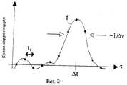
фиг. 3 иллюстрирует вычисление кросс-корреляционнвх функций, согласно изобретению;
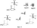
фиг. 4 иллюстрирует сеть GSM, с внедрением технологии временных измерений настоящего изобретения, и идентифицирует логические элементы этой технологии;
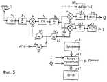
фиг. 5 иллюстрирует основные компоненты схемы телефонного аппарата системы GSM;
фиг. 6 иллюстрирует конкретный способ преодоления влияния многолучевого распространения радиосигналов на измерение относительных временных задержек, согласно изобретению;
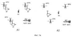
фиг. 7 (а, б, в) изображают различные конфигурации элементов в системе GSM, согласно изобретению;
фиг. 8 иллюстрирует графическое отображение информации о положении на небольшом жидкокристаллическом дисплее, согласно изобретению;
фиг. 9 иллюстрирует взаимное расположение элементов и контрольных пунктов при испытании, проведенном в Кембридже, согласно изобретению.The operating principles of the positioning system of the present invention and the specific application to the technology of the global GSM mobile communication system are described below with reference to the accompanying drawings, in which:
FIG. 1 shows a diagram of the main elements of a system according to the invention;
FIG. 2 is a diagram for determining the coordinates of a system according to the invention;
FIG. 3 illustrates the calculation of cross-correlation functions according to the invention;
FIG. 4 illustrates a GSM network, with the introduction of the time measurement technology of the present invention, and identifies the logical elements of this technology;
FIG. 5 illustrates the main circuit components of a telephone system of a GSM system;
FIG. 6 illustrates a specific method for overcoming the influence of multipath propagation of radio signals on the measurement of relative time delays, according to the invention;
FIG. 7 (a, b, c) depict various configurations of elements in a GSM system according to the invention;
FIG. 8 illustrates a graphical display of position information on a small liquid crystal display according to the invention;
FIG. 9 illustrates the relative positioning of elements and control points in a test conducted in Cambridge according to the invention.
Таблица 1 показывает, каким образом собственная погрешность измерения изменяется в зависимости от отношения сигнал/шум по мощности и числа регистрируемых бит. Table 1 shows how the intrinsic measurement error varies depending on the signal-to-noise ratio in power and the number of bits recorded.
Таблица 2 представляет некоторые результаты испытаний системы определения положения, проведенных в Кембридже. Великобритания. Table 2 presents some test results of the positioning system conducted in Cambridge. United Kingdom.
Ниже приводится описание принципа действия системы
Допустим, что передатчик A (фиг. 1) передает модулированные радиосигналы в пределах полосы частот шириной Δv с центральной частотой V0. Сигналы принимаются неподвижной базовой станцией О и подвижным приемником R.The following is a description of the principle of the system.
Assume that transmitter A (FIG. 1) transmits modulated radio signals within a frequency band of width Δv with a center frequency of V0 . Signals are received by the fixed base station O and the mobile receiver R.
Декартовы координаты (x, у) относительно осей с началом координат, находящимся в местоположении базовой станции, показаны на фиг. 2. Оси могут иметь любую ориентацию, но наиболее удобно установить их, привязываясь к карте местности, так, чтобы ось у лежала в направлении север-юг. Вектор


Передатчик A передает сигналы непрерывно. В заданный момент времени радиоприемники, расположенные в О и R, начинают принимать и регистрировать короткие отрезки передаваемой информации. Этот момент может быть отмечен, например, поступлением запускающего сигнала, переданного из А, или запускающего сигнала, выделенного из потока обычных сигналов, излучаемых передатчиком А, или запускающего сигнала, генерируемого локально. Последний из них может быть получен, например, с использованием импульса короткой длительности, полученного из заранее синхронизированных высокоточных часов, находящихся в приемниках R и О. В цифровой версии сигналы могли бы сначала преобразовываться из несущей Vo в основную полосу частот, преобразовываться в цифровую форму, и затем регистрироваться в динамической памяти. Хотя в приемниках О и R регистрация происходит почти одновременно, все же между двумя моментами регистрации будет иметь место временной сдвиг, который обуславливается и разницей в расстояниях AO и AR, и ошибкой синхронизации между появлением запускающего сигнала в точках O и R. Допустим, сдвиг Δt - это временной сдвиг, он задается выражением
где ε - ошибка синхронизации и v - скорость распространения радиосигналов.Transmitter A transmits signals continuously. At a given point in time, radios located in O and R begin to receive and register short pieces of transmitted information. This moment can be noted, for example, by the arrival of a trigger signal transmitted from A, or a trigger signal isolated from the stream of conventional signals emitted by transmitter A, or a trigger signal generated locally. The last of them can be obtained, for example, using a pulse of short duration, obtained from pre-synchronized high-precision clocks located in the receivers R and O. In the digital version, the signals could first be converted from the carrier Vo to the main frequency band, converted to digital form , and then register in dynamic memory. Although registration at the O and R receivers occurs almost simultaneously, nevertheless, there will be a time shift between the two moments of registration, which is caused by the difference in the distances AO and AR, and a synchronization error between the appearance of the trigger signal at points O and R. Suppose, the shift Δt is a time shift, it is given by the expression
where ε is the synchronization error and v is the propagation velocity of the radio signals.
Оценка временного сдвига Δt может быть получена из кросс-корреляции значений, сформированных в O и R. Каналы связи КС1 и КС2 (фиг.1) представляют собой передачу представлений сигналов, сформированных на каждой приемной станции, в процессор определения положения ПрОП. Природа каналов связи, т.е. передают ли они информацию в режиме, близком к режиму реального времени или вносят задержки, в принципе не имеет значения. Значение имеет только то, что копии значений, сформированных каждой приемной станцией, собираются вместе в процессоре определения положения для сравнения друг с другом. An estimate of the time shift Δt can be obtained from the cross-correlation of the values generated in O and R. The communication channels KC1 and KC2 (Fig. 1) represent the transmission of the representations of the signals generated at each receiving station to the processor for determining the position of the PROP. The nature of the communication channels, i.e. Whether they transmit information in a mode close to real-time or introduce delays, in principle, it does not matter. The only thing that matters is that copies of the values generated by each receiving station are collected together in the position determination processor for comparison with each other.
Взаимная корреляция двух значений выполняется процессором определения положения с использованием любого подходящего средства. В случае цифровых сигналов, возможно, лучше всего выполнять кросс-корреляцию микропроцессором, который вычисляет оценки функции на дискретных интервалах временного сдвига τ, соответствующих интервалу осуществления выборки ts, как изображено точками на фиг. 3. Маловероятно, чтобы пик функции совпал с конкретной выборкой, так что микропроцессор должен также строить по точкам интерполяционную функцию, изображенную пунктирной кривой, для получения более точной оценки положения пика. Значение τ, соответствующее пику, и есть оценочное значение временного сдвига Δt.Cross-correlation of the two values is performed by the position determination processor using any suitable means. In the case of digital signals, it may be best to cross-correlate with a microprocessor that calculates function estimates at discrete time-shift intervals τ corresponding to the sampling interval ts , as shown by dots in FIG. 3. It is unlikely that the peak of the function coincides with a particular sample, so the microprocessor must also plot the points of the interpolation function shown by the dashed curve to obtain a more accurate estimate of the position of the peak. The value of τ corresponding to the peak is the estimated value of the time shift Δt.
Этот процесс квази-одновременной регистрации, передачи по одному или более каналам связи, сбора копий в одном месте, и оценки значения временного сдвига Δt из кросс-корреляции, должен выполняться по меньшей мере с использованием двух или трех пространственно разделенных передатчиков. Если на станциях O и R имеется средство для достаточно точной синхронизации, то достаточно, главным образом, двух измерений. В противном случае, если ошибка синхронизации ε - неизвестна, что бывает чаще всего, то необходимо по меньшей мере три измерения. Предположим для последнего случая (когда ε - неизвестна), что A, B и C - это три передатчика, находящихся в точках векторов


Эти три нелинейных уравнения могут быть решены для того, чтобы найти неизвестные x, у и ε. Таким образом, определяется положение подвижного объекта. Фактически, решение этих трех уравнений вообще неоднозначно с двумя возможными парами координат (x, у). Часто они достаточно далеки друг от друга, в случае чего очевидно, какой из них является правильным результатом (например, только одно из решений может находиться в пределах треугольника, образованного тремя передатчиками). Но если неоднозначность должна решаться автоматически, то необходимо контролировать дополнительный передатчик
Точность способа зависит от ошибки и оценочной функции временного сдвига Δt, выведенной из кросс-корреляции, и имеется три главных фактора, влияющих на эту ошибку. Во-первых, на точность результата влияет ширина кросс-корреляционной функции, так как более широкая функция дает менее острый пик. Ширина оценочной функции обратно пропорциональна ширине полосы частот Δv передаваемых сигналов. Следовательно, передаваемые сигналы с более широкой полосой частот обеспечивают более точное определение истинного положения. Следует отметить, что "ширина полосы частот" может охватывать все сигналы, излучаемые из определенной мачтовой радиоантенны, а не только один конкретный канал. Например, если десять смежных каналов, шириной 200 КГц каждый, были активны в пределах полной полосы частот шириной 2 МГц, то можно, используя широкополосный приемник или приемник, который может принимать одновременно несколько каналов, использовать все десять каналов сразу, и таким образом получать точность, соответствующую ширине полосы 2 МГц. Если некоторые из каналов бездействовали, то можно получить результирующую точность, соответствующую наибольшему разделению двух каналов.This process of quasi-simultaneous recording, transmission over one or more communication channels, collecting copies in one place, and estimating the time offset Δt from cross-correlation should be performed using at least two or three spatially separated transmitters. If at stations O and R there is a means for sufficiently accurate synchronization, then mainly two measurements are sufficient. Otherwise, if the synchronization error ε - is unknown, which happens most often, then at least three measurements are necessary. Suppose for the latter case (when ε is unknown) that A, B and C are three transmitters located at the points of the vectors
These three nonlinear equations can be solved in order to find the unknown x, y and ε. Thus, the position of the moving object is determined. In fact, the solution of these three equations is generally ambiguous with two possible pairs of coordinates (x, y). Often they are far enough from each other, in which case it is obvious which of them is the correct result (for example, only one of the solutions can be within the triangle formed by three transmitters). But if ambiguity should be resolved automatically, then an additional transmitter must be controlled
The accuracy of the method depends on the error and the estimated time shift function Δt derived from cross-correlation, and there are three main factors that influence this error. First, the accuracy of the result is affected by the width of the cross-correlation function, since a wider function gives a less sharp peak. The width of the evaluation function is inversely proportional to the bandwidth Δv of the transmitted signals. Consequently, transmitted signals with a wider frequency band provide a more accurate determination of the true position. It should be noted that the "bandwidth" can cover all the signals emitted from a particular mast radio antenna, and not just one specific channel. For example, if ten adjacent channels, each 200 KHz wide, were active within the full frequency band of 2 MHz wide, then using a broadband receiver or a receiver that can receive several channels simultaneously, you can use all ten channels at once, and thus get accuracy corresponding to a bandwidth of 2 MHz. If some of the channels were inactive, then you can get the resulting accuracy corresponding to the largest separation of the two channels.
Во-вторых, важно отношение сигнал/шум r по мощности сигналов. Предположим, что регистрируются однобитовые выборки принимаемых сигналов, преобразованных сначала в основную полосу частот. Каждая выборка представляет собой "единицу" или "ноль" в зависимости от того, каким был сигнал в момент осуществления выборки: больше или меньше нуля. Также предполагают, что сигналы заключены в пределах сплошной полосы частот, простирающейся от нуля до Δv, и что их выборка осуществляется с минимально допустимой частотой опроса (частотой Найквиста), равной 2Δv. Погрешность оценки положения пика Δτ связана со средним числом g(r) последовательных выборок, которые содержат только одну ошибку, описываемую приблизительным выражением
где N - полное число выборок, используемых в кросс-корреляции. Минимальное значение g составляет 2, поскольку даже тогда, когда нет никакого сигнала, однобитовые выборки имеют равную вероятность оказаться правильными или неправильными. Здесь мы предположили, что кросс-корреляционная функция имеет скорее треугольную форму, чем форму квадрата функции sinc, ожидаемую для шумовых сигналов и прямоугольных полосовых фильтров. Погрешности оценки положения Δτ складывается квадратично, как и погрешности положения Δx, где Δx = vΔτ. Отношение между g(r) и r может быть получено из следующих выражений при условии, что сигналы являются сигналами типа шума
q(r) = 1/p

При выборе полосы частот Δv, равной 200 КГц, получены результаты, приведенные в таблице 1.Secondly, the signal-to-noise ratio r in terms of signal power is important. Suppose that single-bit samples of received signals are converted, first converted to the main frequency band. Each sample represents a “unit” or “zero” depending on what the signal was at the time of the sample: more or less than zero. It is also assumed that the signals are enclosed within a continuous frequency band extending from zero to Δv, and that they are sampled with the minimum allowable polling frequency (Nyquist frequency) equal to 2Δv. The error in estimating the position of the peak Δτ is related to the average number g (r) of consecutive samples that contain only one error, described by an approximate expression
where N is the total number of samples used in cross-correlation. The minimum value of g is 2, because even when there is no signal, single-bit samples are equally likely to be correct or incorrect. Here we hypothesized that the cross-correlation function has a triangular shape rather than a square shape of the sinc function expected for noise signals and rectangular bandpass filters. The errors in estimating the position Δτ are quadratic, as are the errors in the position Δx, where Δx = vΔτ. The relationship between g (r) and r can be obtained from the following expressions, provided that the signals are noise type signals
q (r) = 1 / p
When choosing a frequency band Δv equal to 200 KHz, the results are shown in table 1.
Как отмечено выше, ошибки измерений от каждого передатчика Δx1, Δx2, Δx3 должны складываться в квадрате друг с другом и с любыми другими ошибками оценки положения подвижного объекта. Следует обратить внимание на то, что достаточно хорошие результаты могут быть получены даже в условиях плохого приема.As noted above, the measurement errors from each transmitter Δx1 , Δx2 , Δx3 must be added in the square with each other and with any other errors in the assessment of the position of the moving object. It should be noted that fairly good results can be obtained even in conditions of poor reception.
В-третьих, и что обычно практически наиболее важно, имеется ошибка, вносимая отсутствием точного знания траекторий, по которым сигналы достигают подвижного объекта. Многолучевое распространение радиосигналов уширяет кросс-корреляционную функцию, затрудняя оценку положения максимума. Оно также может привести к кросс-корреляционной функции с несколькими пиками, в которой нужный пик имеет более низкую амплитуду, чем другие. Если все сигналы прибывают косвенными маршрутами, то может вообще не быть никакого пика, соответствующего траектории прямого распространения. Однако, следует отметить, что многолучевое распространение радиосигналов всегда приводит к задержке сигналов по сравнению с распространением сигналов по прямой траектории. При условии, когда антенна базовой станции находится явно выше мешающих отражений от окружающих объектов, так что она принимает только наиболее прямые сигналы, тогда задержанные сигналы на подвижном объекте всегда появляются на задней стороне пика кросс-корреляции. В этих обстоятельствах можно ослабить влияние многолучевого распространения радиосигналов, как объясняется ниже. При построении подходящей интерполяционной функции по дискретным выборкам важно выбрать наименьшее значение τ, при котором сосредоточена значительная часть сигнала, в качестве того значения временной задержки Δt, которое должно использоваться в вычислении положения, что предпочтительнее использования непосредственно положения пика. Thirdly, and what is usually practically most important, there is an error introduced by the lack of accurate knowledge of the paths along which the signals reach a moving object. The multipath propagation of radio signals broadens the cross-correlation function, making it difficult to estimate the position of the maximum. It can also lead to a cross-correlation function with several peaks, in which the desired peak has a lower amplitude than others. If all signals arrive via indirect routes, then there may be no peak at all corresponding to the direct propagation path. However, it should be noted that the multipath propagation of radio signals always leads to a delay of signals compared with the propagation of signals along a direct path. Provided that the antenna of the base station is clearly above interfering reflections from surrounding objects, so that it receives only the most direct signals, then the delayed signals on the moving object always appear on the back side of the cross-correlation peak. In these circumstances, the influence of multipath propagation of radio signals can be attenuated, as explained below. When constructing a suitable interpolation function from discrete samples, it is important to choose the smallest value of τ at which a significant part of the signal is concentrated, as the value of the time delay Δt that should be used in calculating the position, which is preferable to using the peak position itself.
Использование способа для глобальной системы мобильной связи GSM. Using the method for the global GSM mobile communication system.
Сигналы, излучаемые передатчиками в сети GSM, являются сложными. Гибкость и пропускная способность. Встроенные в ее структуру таковы, что трудно, если не невозможно, жертвовать ими для того, чтобы предсказать точно, как распределенный спектр (приблизительно 900 МГц и 1800 МГц в Европе) будет использоваться в произвольный момент. Полоса частот разделяется на ряд высокочастотных (ВЧ) каналов шириной 200 КГц, каждый из которых передает частотно-модулированные (ЧМ) сигналы, разделенные во времени на последовательность кадров. Основная единица - это так называемый кадр множественного доступа с временным разделением каналов (МДВРК) длительностью 4.615 мс, дополнительно разделенный на 8 временных интервалов. Каждый временной интервал несет 156.25 бит со скоростью 270 Кбит/сек и может представлять "нормальный пакет" данных и сопровождающую информацию, "пакет частотной коррекции" определенной конфигурации, "пакет синхронизации" данных и синхронизирующую информацию, или "пакет доступа" с синхронизирующей последовательностью и данными. Каждый из этих пакетов также несет заголовок, последний элемент и биты признака защиты. Число временных интервалов, используемых в произвольный момент времени в данном кадре, и число высокочастотных несущих, передаваемых из данного передатчика, зависит от конфигурации системы и от интенсивности потока транспорта в этот момент. Однако в наименее вероятном случае, когда все спокойно, одна из несущих высоких частот будет всегда действовать, неся так называемый радиовещательный канал управления (РКУ, логический канал), осуществляющий опрос мобильных телефонных аппаратов в соответствующих участках сотовой связи, посредством передачи одного пакета доступа в каждом кадре множественного доступа с временным разделением каналов (МДВРК). Следовательно, можно полагаться на то, что с каждой антенной мачты передатчика передается по меньшей мере один частотно-модулированный радиосигнал с шириной полосы приблизительно 200 КГц, который можно использовать для локации положения объекта. The signals emitted by the transmitters in the GSM network are complex. Flexibility and bandwidth. The built-in structures are such that it is difficult, if not impossible, to sacrifice them in order to predict exactly how the distributed spectrum (approximately 900 MHz and 1800 MHz in Europe) will be used at any time. The frequency band is divided into a number of high-frequency (HF) channels with a width of 200 KHz, each of which transmits frequency-modulated (FM) signals, divided in time into a sequence of frames. The basic unit is the so-called time division multiple access (TDMA) frame of 4.615 ms duration, further divided into 8 time slots. Each time interval carries 156.25 bits at a speed of 270 Kbps and can represent a “normal packet” of data and accompanying information, a “frequency correction packet” of a specific configuration, a “synchronization packet” of data and synchronization information, or an “access packet” with a synchronization sequence and data. Each of these packets also carries a header, the last element, and bits of a security tag. The number of time slots used at an arbitrary point in time in a given frame, and the number of high-frequency carriers transmitted from a given transmitter, depends on the configuration of the system and on the traffic flow intensity at that moment. However, in the least probable case, when everything is calm, one of the high-frequency carriers will always act, carrying the so-called broadcasting control channel (RCU, logical channel), which polls mobile telephones in the corresponding areas of cellular communication, by transmitting one access packet in each time division multiple access (TDMA) frame. Therefore, you can rely on the fact that at least one frequency-modulated radio signal with a bandwidth of approximately 200 KHz is transmitted from each antenna mast of the transmitter, which can be used to locate the position of the object.
Региональная сеть GSM, включающая систему позиционирования настоящего изобретения (фиг. 4) содержит базовые приемники (БП), помеченные индексами БПA, БПB, БПC, и т.д. для каждого соответствующего передатчика системы GSM A, B, C и т. д., способные принимать сигналы не только из их собственных локальных передатчиков, но и также по меньшей мере из двух других отдаленных передатчиков, ряд мобильных телефонных аппаратов, включающих мобильные приемники (ПП), помеченные индексами ППA, ППB, ППC, и т.д., действующие в заданной области. Важно то, что эти мобильные телефонные аппараты могут принимать сигналы из того же набора удаленных передатчиков также, как и из местного передатчика. Как отмечено выше, нет необходимости добиваться высокого отношения сигнал/шум для приема сигналов из удаленных передатчиков, но сама необходимость приема таких сигналов может ограничить применимость этой системы в сельской местности, где участки сотовой связи находятся на большом расстоянии. Система содержит также процессор определения положения (ПрОП) и базу данных системной службы (БДСС). Это устройство, которое обеспечивает данные, связанные с положением, соответствующие запросу абонентом системы определения положения. Например, абоненту может понадобиться инструкция для поиска вокзала в незнакомом городе. Процессор определения положения вычислит положение абонента и пошлет данные о положении в базу данных системной службы вместе с запросом абонента. База данных даст ответ посредством требуемого списка инструкций. Изображенная конфигурация, в которой процессор определения положения является автономным удаленным блоком, является только одной из нескольких возможных конфигураций. Например, процессор определения положения (ПрОП) и подвижный приемник (ПП) могли бы быть объединены вместе внутри телефонного аппарата так, что бы обработка положения проводилась собственным компьютером мобильного телефонного аппарата.The regional GSM network, including the positioning system of the present invention (Fig. 4), contains base receivers (PSUs) labeled with the indices BPA , PSUB , PSUC , etc. for each respective transmitter of the GSM system A, B, C, etc., capable of receiving signals not only from their own local transmitters, but also from at least two other remote transmitters, a number of mobile telephones including mobile receivers (PP ) marked by the indices PPA , PPB , PPC , etc., acting in a given area. Importantly, these mobile telephones can receive signals from the same set of remote transmitters as well as from a local transmitter. As noted above, there is no need to achieve a high signal-to-noise ratio for receiving signals from remote transmitters, but the very need to receive such signals can limit the applicability of this system in rural areas, where mobile communication areas are located at a long distance. The system also includes a position determination processor (POP) and a system service database (BDSS). This is a device that provides position related data corresponding to a request by a subscriber of a position determination system. For example, a subscriber may need instructions for finding a station in an unfamiliar city. The position determination processor will calculate the position of the subscriber and send position data to the system service database along with the subscriber’s request. The database will provide an answer through the required list of instructions. The configuration shown, in which the position determination processor is a standalone remote unit, is only one of several possible configurations. For example, a position determination processor (POP) and a mobile receiver (PP) could be combined together inside a telephone so that position processing would be carried out by the mobile phone's own computer.
Необходимо установить код запускающего сигнала, который передается периодически из каждого передатчика, возможно в пределах логического канала РКУ. Как отмечено выше, то может быть специальный код, задаваемый в пределах существующей структуры GSM, или повторяющийся элемент самих стандартных сигналов GSM, таких, как поступление номера кадра с тремя нулями на конце, происходящее каждые 4 секунды. Поступление кода запускающего сигнала приводит к тому, что активный подвижный приемник (ПП) начинает обработку записи сигналов по меньшей мере из трех передатчиков. Иногда может существовать коммерческая выгода в создании кода запускающего сигнала, уникального для конкретного оператора или для конкретного мобильного телефонного аппарата, таким образом обеспечивая одно из средств оплаты службы определения положения абонентами. Имеется, конечно, много других возможных путей оплаты. Код запускающего сигнала также активизирует механизм регистрации в базовом приемнике (БП), связанном с передатчиком системы GSM. Поскольку большинство мобильных телефонных аппаратов системы GSM могут принимать сразу только один высокочастотный канал, то сначала должен быть установлен порядок регистрации сигналов из удаленных передатчиков, например, путем использования сигналов сотового радиовещания или службы коротких сообщений. Ниже показано, что может быть также необходимо записывать сигналы локального передатчика второй раз, чтобы учесть дрейф на протяжении периода записи. Если для каждого из двух удаленных передатчиков регистрируется 2048 выборок (по 1024 выборки для синфазного 1 и квадратурного Q сигналов), и 4096 выборок для локального передатчика (два набора по 2048 выборок), то полная обработка может быть выполнена за несколько сотен миллисекунд, включая время, затраченное на переключение между каналами и на настройку на каждую новую частоту. Записи, выполненные подвижным приемником (ПП) и базовым приемником (БП), затем посылаются любым подходящим средством в процессор определения положения (ПрОП). Подвижный приемник мог бы использовать например, временные интервалы в сигналах системы GSM или он мог бы направлять запрос передачи данных. Базовый приемник может посылать свои сигналограммы по наземной линии связи в удаленный процессор определения положения. Процессор принимает и транслирует в память собственные копии сигналов, принимаемых базовым и подвижным приемниками, для корреляционной и позиционной обработки. Он мог бы также использовать другие параметры сигналов, регистрируемых двумя приемными станциями, такие как интенсивность сигнала. It is necessary to set the trigger code, which is transmitted periodically from each transmitter, possibly within the logical channel of the RCC. As noted above, it can be a special code defined within the existing GSM structure, or a repeating element of the standard GSM signals themselves, such as the arrival of a frame number with three zeros at the end, occurring every 4 seconds. The receipt of the trigger code leads to the fact that the active mobile receiver (PP) begins processing the recording of signals from at least three transmitters. Sometimes there may be commercial benefits in creating a trigger code that is unique to a particular operator or to a particular mobile telephone, thereby providing one of the means of payment for subscriber location services. Of course, there are many other possible payment methods. The trigger code also activates the registration mechanism in the base receiver (PSU) associated with the transmitter of the GSM system. Since most mobile phones of the GSM system can receive only one high-frequency channel at once, the procedure for registering signals from remote transmitters must first be established, for example, by using cellular broadcasting signals or short message service. It is shown below that it may also be necessary to record the local transmitter signals a second time to allow for drift over the recording period. If 2048 samples are recorded for each of the two remote transmitters (1024 samples each for in-
Сразу после трансляции данных процессор начинает выполнять кросс-корреляционный анализ. Можно использовать стандартные способы, но предпочтительным является способ, описанный ниже, который уменьшает эффекты многолучевого распространения радиосигналов. Имея выполненные оценки временных сдвигов Δta, Δtb, Δtc, процессор решает уравнения для оценки координат x и у. Однако необходимость последовательного приема сигналов из трех передатчиков вносит сложность, состоящую в том, что ошибка синхронизации ε все время изменяется и вряд ли может быть постоянной на протяжении периода регистрации. Можно моделировать эту ошибку на коротких промежутках времени как сумму постоянного сдвига и линейного наклона
ε = ε0+ε1t,
где ε0+ε1 - константы, t - время. Появляется дополнительная неизвестная величина ε1, которую необходимо оценить, это можно сделать, производя запись сигналов из локального передатчика заново во второй раз (и на базовой станции и на подвижном объекте). Теперь получается четыре значения временного сдвига Δt, полученные в последовательные моменты времени t1, t2, t3, и t4, и уравнения (1) приобретают вид


Первое и последнее из этих уравнений можно вычесть, чтобы получить выражение
Δta(t4)-Δta(t1) = ε1(t4-t1),
из которого можно найти ε1. Следовательно, имея четыре оценки временного сдвига Δt, можно численно решить уравнения (2) для определения координат x и у.Immediately after data transmission, the processor begins to perform cross-correlation analysis. Standard methods can be used, but the method described below is preferred, which reduces the effects of multipath propagation of radio signals. Having made estimates of the time shifts Δta , Δtb , Δtc , the processor solves the equations for estimating the x and y coordinates. However, the need for sequential reception of signals from three transmitters introduces a difficulty in that the synchronization error ε changes all the time and can hardly be constant during the recording period. You can simulate this error over short periods of time as the sum of a constant shift and a linear slope.
ε = ε0 + ε1 t,
where ε0 + ε1 are constants, t is time. An additional unknown quantity ε1 appears, which must be estimated; this can be done by recording the signals from the local transmitter again for the second time (both at the base station and at the moving object). Now we get four values of the time shift Δt obtained at successive times t1 , t2 , t3 , and t4 , and equations (1) take the form
The first and last of these equations can be subtracted to obtain the expression
Δta (t4 ) -Δta (t1 ) = ε1 (t4 -t1 ),
from which ε1 can be found. Therefore, having four estimates of the time shift Δt, we can numerically solve equations (2) to determine the coordinates x and y.
Мобильные телефонные аппараты, содержащие многоканальные приемники, способные принимать все три канала одновременно, не нуждаются в повторении регистрации сигналов из передатчика A, поскольку скорость дрейфа между тактовыми импульсами (измеряемая параметром ε1) в этом случае не имеет значения и не должна определяться. Высококачественные одноканальные мобильные телефонные аппараты могут также обходиться без повторной регистрации, если дрейф ошибки датчика тактовых импульсов достаточно мал, чтобы им пренебречь.Mobile telephones containing multichannel receivers capable of receiving all three channels simultaneously do not need to repeat the registration of signals from transmitter A, since the drift velocity between clock pulses (measured by parameter ε1 ) in this case does not matter and should not be determined. High-quality single-channel mobile telephones can also do without re-registration if the error drift of the clock sensor is small enough to be neglected.
Как отмечено выше, почти все элементы аппаратных средств, необходимые внутри мобильного телефонного аппарата системы GSM, уже существуют для стандартного функционирования системы GSM. На фиг. 5 показано типичное исполнение. Радиочастотные сигналы в диапазоне 900 МГц или 1800 МГц принимаются антенной 1, усиливаются в высокочастотном усилителе (УВЧ) 2 и фильтруются высокочастотным полосовым фильтром 3 перед тем, как они будут преобразованы в промежуточную частоту ПЧ в смесителе 4 сигналом локального генератора ЛГ1, генерируемым генератором 5. Локальный генератор ЛГ1 уже включает необходимую способность переключения канала. Важно, чтобы частота была синхронизирована по фазе с частотой задающего генератора ЗГ, как правило, кварцевого генератора 6. Это также требование для нормальной работы системы GSM, поскольку оно не вносит дополнительных затрат. Сигналы ПЧ усиливаются усилителем 7, фильтруются полосовым фильтром 8 и преобразуются в основную полосу частот в квадратурных смесителях 9 и 10 с использованием сигнала ЛГ2 из второго локального генератора 11. Как и локальный генератор ЛГ1, этот второй генератор также должен быть синхронизирован по фазе с задающим генератором. Однако, точная настройка частоты (автоматическая подстройка частоты, АПЧ) также часто вводится в контур, который должен поддерживать частоту постоянной во время процесса регистрации. Сигналы с квадратурных выходов фильтруются низкочастотными фильтрами 12 и 13, преобразуются в цифровую форму в аналого-цифровых преобразователях 14 и 15, на выходе имеются битовые потоки, обозначенные I и Q. Теперь для определения положения требуется, чтобы микропроцессор 16 просто зарегистрировал битовые потоки в динамическом ЗУПВ 17 под управлением программы 18. Может потребоваться некоторая дополнительная память. Основная модификация, необходимая для обеспечения возможности определения положения, состоит во встроенной программе, выполняемой в микропроцессоре, и в связи с этим может понадобиться модернизация самого процессора в сторону быстродействия. Подобная аппаратура необходима для базовой приемной станции.As noted above, almost all of the hardware elements needed inside the GSM mobile phone already exist for the standard functioning of the GSM system. In FIG. 5 shows a typical embodiment. RF signals in the 900 MHz or 1800 MHz range are received by
Коммерчески ограничивающим элементом в системе настоящего изобретения, вероятно, является средство, с помощью которого сигналы, зарегистрированные на базовой станции и подвижном объекте, передаются в процессор определения положения для кросс-корреляции. Поэтому важно в максимально возможной степени уменьшить число передаваемых бит. Как отмечено выше, осуществление однобитовой выборки производит адекватные результаты даже при условии приема слабого сигнала, и, хотя можно получить несколько более высокую точность с использованием, скажем, осуществления двухбитовой выборки. Увеличение загрузки связи нерационально. Лучше удвоить число однобитных выборок, и следовательно, удвоить длину интервала выборки, чем использовать двухбитовые выборки. Может также потребоваться измерение обоих каналов I и Q и выполнение сложной кросс-корреляции, так как сигналы базовой станции и подвижного объекта вряд ли будут синфазны друг с другом, а кварцевые генераторы не синхронизированы между собой. Пусть квадратурные битовые потоки в подвижном объекте (ПП) представлены величинами I и Q, где
I = V1(t)cos(θ1)
и Q = V2(t)sin(θ1), где θ1 - фаза сигналов, V1(t), V2(t) - их амплитуды. Соответствующие величины, зарегистрированные на базовой станции (БП), следующие:

I = V1 (t) cos (θ1 )
and Q = V2 (t) sin (θ1 ), where θ1 is the phase of the signals, V1 (t), V2 (t) are their amplitudes. The corresponding values recorded at the base station (BP) are as follows:
Микропроцессор затем должен вычислить четыре кросс-корреляции, соответствующих величинам II', QQ, lQ, I'Q, и затем искать пик величины p, где
Разность фаз θ = θ1-θ2, может быть также получена из выражения
и она может использоваться для устранения небольшого частотного сдвига между локальными генераторами на базовой станции и подвижном объекте, так, чтобы осуществлялось возможно более продолжительное интегрирование.The microprocessor then must calculate four cross-correlations corresponding to the values II ', QQ, lQ, I'Q, and then look for the peak of p, where
The phase difference θ = θ1 -θ2 can also be obtained from the expression
and it can be used to eliminate a small frequency shift between the local oscillators at the base station and the mobile unit, so that a longer integration is possible.
Уравнения (1) и (2), приведенные выше, показывают, каким образом можно использовать оценки временных задержек Δt для получения положения (x, у) подвижного объекта и ошибки синхронизации ε между базовой станцией и подвижным объектом. Для этого процесса самым важным является точность, с которой из кросс-корреляционных функций можно получить оценки временных задержек Δt. Как отмечено выше, главное ограничение точности, вызвано многолучевым распространением сигналов из передатчика системы GSM к подвижному объекту. Предполагается, что антенна на базовой станции установлена достаточно высоко над мешающими отражениями от окружения, чтобы гарантировать, что многолучевое распространение достаточно мало, чтобы им пренебречь. При этих обстоятельствах многолучевое распространение радиосигналов к подвижному объекту приводит к уширению пика кросс-корреляции в сторону более длинных временных задержек, поскольку сигналы по наиболее прямой траектории поступают первыми. Предпочтительный способ получения оценки временной задержки Δt основан на использовании автокорреляционной функции (АКФ) сигналов базовой станции и подвижного объекта, а также кросс-корреляционной функции (ККФ) между ними. В изобретении использованы две автокорреляционные функции, чтобы вывести вероятную форму кросс-корреляционной функции, и затем подогнать этот "эталонный график" к кросс-корреляционной функции для получения лучшей оценки временной задержки Δt.
Две автокорреляционные функции АКФПП и АКФБП наряду с кросс-корреляционной функцией ККФ, можно получить любым из стандартных средств (см. например в "Random Data: analysis and measurement procedures" by J.S. Bendat and A.G.Piersol, Wiley-interscience, 1971, ("Случайные данные: анализ и процедуры измерения"). Предпочтительны способы, которые включают быстрые преобразования Фурье (БПФ). Автокорреляционная функция АКФБП является хорошей оценкой "собственной" автокорреляции передаваемых сигналов (пренебрежимо малый эффект многолучевого распространения радиосигналов), тогда как автокорреляционная функция АКФПП искажается сигналами многолучевого распространения, то есть сигналами, задержанными более чем на 30 м эквивалентного пути. На фиг. 6 изображен частный пример, где записанная кривая A представляет собой автокорреляционную функцию АКФБП, а записанная кривая Б представляет собой автокорреляционную функцию АКФПП. Из диаграммы видно, что многолучевое распространение радиосигналов порождает в записанной кривой Б вторичные пики, которые появляются с обеих сторон от главного пика, так как автокорреляционная функция всегда симметрична. "Эталонный график" строят, беря левую часть автокорреляционной функции АКФБП (часть записанной кривой A слева от центрального пика, соответствующая отрицательной оси времени) и присоединяя ее к правой части АКФПП (записанная кривая Б справа от центрального пика. Соответствующая положительной оси времени). Этот "эталонный график" изображен в виде записанной кривой B. Измеренная кросс-корреляционная функция ККФ изображена в виде записанной кривой Г, и видно, что "эталонный график" В воспроизводит основные черты. Затем получают оценку временного сдвига Δt, подгоняя эталонный график к измеренной кросс-корреляционной функции ККФ, с использованием любого стандартного способа, допуская, чтобы амплитуды из двух половин эталонного графика были независимыми параметрами, также, как Δt. Процедура аппроксимации также дает параметр "качество аппроксимации", который можно использовать, как основание для отклонения или включения данных.Equations (1) and (2) above show how the estimates of time delays Δt can be used to obtain the position (x, y) of the moving object and the synchronization error ε between the base station and the moving object. For this process, the most important is the accuracy with which estimates of the time delays Δt can be obtained from cross-correlation functions. As noted above, the main limitation of accuracy is caused by the multipath propagation of signals from the transmitter of the GSM system to a moving object. It is assumed that the antenna at the base station is mounted high enough above the interfering reflections from the environment to ensure that the multipath is small enough to be neglected. Under these circumstances, the multipath propagation of radio signals to a moving object leads to a broadening of the cross-correlation peak towards longer time delays, since the signals arrive first along the most direct path. The preferred method of obtaining an estimate of the time delay Δt is based on the use of an autocorrelation function (ACF) of the signals of the base station and the moving object, as well as a cross-correlation function (CCF) between them. Two autocorrelation functions were used in the invention to derive the probable form of the cross-correlation function, and then fit this “reference graph” to the cross-correlation function to obtain a better estimate of the time delay Δt.
The two autocorrelation functions of ACFPP and ACFBP, along with the cross-correlation function of CCF, can be obtained using any of the standard tools (see, for example, in "Random Data: analysis and measurement procedures" by JS Bendat and AGPiersol, Wiley-interscience, 1971, " Random data: analysis and measurement ") are preferred methods which comprise fast Fourier transform (FFT) autocorrelation function ACFPD is a good estimate.." procedure own "autocorrelation of the transmitted signals (negligible multipath effect of the radio signals), whereas the autocorrelation Zion function ACFPP distorted multipath signals, i.e. signals delayed by more than 30 m equivalent path. FIG. 6 shows a specific example where the recorded curve A represents the autocorrelation function ACFPD and recorded curve B represents the autocorrelation function ACFPP : The diagram shows that the multipath propagation of radio signals generates secondary peaks in the recorded curve B, which appear on both sides of the main peak, since the autocorrelation function is where is symmetrical. The “reference graph” is constructed by taking the left side of the ACFBP autocorrelation function (the part of the recorded curve A to the left of the central peak corresponding to the negative time axis) and attaching it to the right side of the ACFBP (recorded curve B to the right of the central peak. Corresponding to the positive time axis) . This "reference graph" is depicted as a recorded curve B. The measured cross-correlation function of the CCF is depicted as a recorded curve D, and it is seen that the "reference graph" B reproduces the main features. An estimate of the time shift Δt is then obtained by fitting the reference graph to the measured cross-correlation function of the CCF using any standard method, assuming that the amplitudes of the two halves of the reference graph are independent parameters, like Δt. The approximation procedure also gives the parameter "approximation quality", which can be used as a basis for rejecting or including data.
В случаях, когда более трех передатчиков системы GSM могут приниматься как на базовой станции, так и на подвижном объекте, может быть выгодно использовать их все в процессе определения положения, особенно если одна или две из траекторий по существу искривлены. В таком случае высокое качество параметра аппроксимации может обеспечить весовой коэффициент для каждого Δt, используемого для определения положения. In cases where more than three transmitters of the GSM system can be received both at the base station and at the mobile site, it may be advantageous to use all of them in the process of determining the position, especially if one or two of the trajectories are essentially curved. In this case, the high quality of the approximation parameter can provide a weight coefficient for each Δt used to determine the position.
Мобильные телефонные аппараты системы GSM включают многоуровневые аналого-цифровые преобразователи (АЦП) и используют адаптивные способы обработки, чтобы уменьшить ошибки, возникающие в результате многолучевого распространения радиосигналов. Следовательно, в зависимости от конструкции мобильного телефонного аппарата, можно использовать сами демодулированные сигналы для кросс-корреляционной функции, и это предпочтительнее, чем использовать необработанные - потоки данных I и Q из приемников. Такую дополнительную задержку, вносимую адаптивной обработкой, следует, конечно, устранять, и никакой объем обработки не может учесть неизвестную дополнительную длину полностью искривленной траектории сигнала, но тем не менее демодулированные выходные данные могут лучше подходить для оценки временных задержек, чем предварительно обработанные потоки исходных данных I и Q. GSM mobile telephones include multi-level analog-to-digital converters (ADCs) and use adaptive processing methods to reduce errors resulting from multipath propagation of radio signals. Therefore, depending on the design of the mobile telephone, it is possible to use the demodulated signals themselves for the cross-correlation function, and this is preferable to using the unprocessed ones - data streams I and Q from the receivers. Such additional delay introduced by adaptive processing should, of course, be eliminated, and no amount of processing can take into account the unknown additional length of the completely curved signal path, but nonetheless, demodulated output data may be better suited for estimating time delays than pre-processed source data streams I and Q.
На фиг. 5 пунктирной линией изображен дискриминатор с частотной модуляцией 19 (ЧМД). ЧМ дискриминация преобразует частотный сдвиг в постоянный сдвиг (в виде постоянного тока) на выходе, так что квадратурные сигналы (I и Q) не требуются, а заменяются одним сигналом J. Это дает два дополнительных преимущества, состоящих в том, что:
а) вдвое меньше данных необходимо передавать по каналам связи, и
б) нет необходимости подстраивать частотный сдвиг в процессоре определения положения, что позволит сократить служебные действия процессора.In FIG. 5, the dashed line shows the discriminator with frequency modulation 19 (FMD). FM discrimination converts the frequency shift to a constant shift (in the form of a direct current) at the output, so that quadrature signals (I and Q) are not required, but are replaced by a single signal J. This has two additional advantages, namely:
a) half as much data must be transmitted over communication channels, and
b) there is no need to adjust the frequency shift in the position determination processor, which will reduce the processor's overhead.
Как отмечено выше, возможны несколько различных конфигураций системы определения положения настоящего изобретения в зависимости от относительных местоположений передатчиков системы GSM (часто называемых базовыми приемопередающими станциями, БППС) подвижных приемников (ПП), базовых приемников (БП), процессора определения положения (ПрОП), и базы данных системной службы (БДСС). На фиг. 7а, 7б, 7в представлены три конфигурации, обозначенные А. Б и В. Каждая из них далее подразделяется на две. Фиг. 7а изображает конфигурацию, в которой процессор определения положения (ПрОП) и база данных системной службы (БДСС) располагаются совместно в положении, удаленном и от базового приемника (БП) и от подвижного приемника (ПП). Это может иметь место, например, когда одна комбинированная система ПрОП/БДСС обслуживает весь регион. В конфигурации А1 каждая базовая приемопередающая станция (БПСС) имеет базовый приемник (БП), расположенный вместе с ней. В конфигурации А2 базовый приемник (БП), обслуживающий локальный участок сотовой связи, окруженный тремя базовыми приемо-передающими станциями (БППС), изображен в пределах локального участка сотовой связи. Конфигурация Б1 и Б2 (фиг. 76) подобны А1 и А2, соответственно, за исключением того, что теперь имеется много процессоров определения положения (ПрОП). В конфигурации Б1 каждая базовая приемо-передающая станция (БППС) имеет присоединенный к ней базовый приемник (БП). В конфигурации Б2 каждый треугольник из трех БППС имеет в своих пределах процессор определения положения (ПрОП), из которых изображен только один. Региональная база данных системной службы (БДСС) остается в удаленном местоположении. Конфигурации В1 и В2 (фиг. 7в) подобны А1 и А2, но в них вычисление положения осуществляется внутри каждого мобильного телефонного аппарата. Возможны также другие конфигурации, каждая из которых имеет относительные преимущества, делающие их подходящими для конкретных коммерческих применений. As noted above, several different configurations of the positioning system of the present invention are possible depending on the relative locations of the GSM system transmitters (often referred to as base transceiver stations, BTSs) of mobile receivers (PP), base receivers (PSU), position determination processor (POP), and system service databases (BDSS). In FIG. 7a, 7b, 7c, three configurations are presented, designated A. B and C. Each of them is further divided into two. FIG. 7a depicts a configuration in which a position determination processor (POP) and a system service database (BSS) are located together in a position remote from both the base receiver (PSU) and the mobile receiver (PP). This may occur, for example, when one combined POP / BDSSS system serves the entire region. In configuration A1, each base transceiver station (BPSS) has a base receiver (BP) located with it. In configuration A2, the base receiver (BP) serving the local area of cellular communication, surrounded by three base transceiver stations (BTS), is depicted within the local area of cellular communication. The configurations B1 and B2 (FIG. 76) are similar to A1 and A2, respectively, except that now there are many positioning processors (POPs). In configuration B1, each base transceiver station (BTS) has a base receiver (PSU) attached to it. In configuration B2, each triangle of the three BTSs has a position determination processor (POP) within its limits, of which only one is shown. The Regional System Service Database (BDSSS) remains at a remote location. The configurations B1 and B2 (Fig. 7c) are similar to A1 and A2, but in them the position is calculated inside each mobile telephone. Other configurations are also possible, each of which has relative advantages, making them suitable for specific commercial applications.
В некоторых коммерческих применениях может быть выгодно отображать информационную карту в графическом виде как часть ответа базы данных системной службы на запрос о координатно-информационном обеспечении. Подобный пример представлен на фиг. 8, которая изображает, как карта участка местности могла бы быть изображена на экране, подсоединенном к процессору определения положения, или на отслеживающей станции. Абонент сделал запрос о направлениях движения к точке, обозначенной закрашенным кружком с меткой Z, и процессор определения положения вычислил, что абонент находится где-то в пределах закрашенного круга с меткой W. Переносной телефонный аппарат абонента содержит жидкокристаллический матричный дисплей, который может отображать маленькие участки большой карты, а также и символьную информацию. Первое изображение, отображаемое на экране мобильного телефонного аппарата, может быть таким, как изображено на панели с пометкой (а) на фиг. 8. Это - крупномасштабная карта участка местности с кругом радиусом 100 м, центрированным в расчетном положении. Дороги помечены цифрами 1, 2, 3 и т.д., соответствующими названиям, указанным на втором изображении на экране, панель (б). При желании абонент может переключать эти изображения на экране - от одного к другому. Панель (в) изображает карту участка местности в большем масштабе вместе с указателем К, который указывает направление к месту назначения, Z. Очевидно, что возможно много других изображений информации на экране, включая изображение адреса места назначения, местных условий движения, приблизительного расстояния, и т.д. В коммерческих целях при необходимости можно изыскать возможность для ограниченной передачи рекламных объявлений на дисплее мобильного телефонного аппарата. In some commercial applications, it may be advantageous to display the information map in graphical form as part of the response of the system service database to the coordinate information support request. A similar example is shown in FIG. 8, which depicts how a site map could be displayed on a screen connected to a positioning processor, or at a tracking station. The subscriber made a request for directions to the point indicated by the filled circle marked with Z, and the position determination processor calculated that the subscriber is somewhere within the filled circle marked with W. The subscriber's portable telephone contains a liquid crystal matrix display that can display small areas large maps, as well as symbolic information. The first image displayed on the screen of the mobile telephone can be as shown on the panel marked (a) in FIG. 8. This is a large-scale map of a site with a circle with a radius of 100 m centered in the calculated position. Roads are marked with
Испытания макетной системы (опытного образца). Tests of the breadboard system (prototype).
Опытный образец с использованием пары стандартных портативных телефонных аппаратов и некоторой дополнительной регистрирующей аппаратуры был установлен в Кембридже, Великобритания. Базовая станция (БП) располагалась в трехэтажном здании вблизи центра города (фиг. 9) с антенной, закрепленной на крыше. Подвижный приемник (ПП) перемещался в автомобиле к различным местоположениям в южной части города, как показано крестиками. Три использовавшихся в испытании передатчика базовой приемо-передающей станции (БППС) системы GSM располагались, соответственно, в центре города, в Большом Шелфорде на юге, и в Фулборне на юго-востоке. Таблица 2 представляет средние ошибки позиционирования по обеим координатам, то есть разность между усредненными значениями приблизительно 10 независимых определений положения и истинными координатами положений, измеренными на карте. Использовались простые методы анализа данных без какого-либо специального устранения эффектов многолучевого распространения радиосигналов. Собственная точность устройства, полученная при испытаниях при совместном расположении на стенде базового приемника и подвижного приемника была менее 20 м (среднеквадратичное значение). Испытания с номерами от 1 до 6 были выполнены при остановке подвижного объекта, испытания с номерами 7-11 были выполнены при скоростях от 40 до 64 км в час. A prototype using a pair of standard portable telephones and some additional recording equipment was installed in Cambridge, UK. The base station (BP) was located in a three-story building near the city center (Fig. 9) with an antenna mounted on the roof. A mobile receiver (PP) moved in a car to various locations in the southern part of the city, as indicated by crosses. The three GSM systems used in the transmitter test of the base transceiver station (BTS) were located, respectively, in the city center, at Big Shelford in the south, and in Fulborn in the southeast. Table 2 presents the average positioning errors for both coordinates, that is, the difference between the averaged values of approximately 10 independent position determinations and the true position coordinates measured on the map. Simple data analysis methods were used without any special elimination of the effects of multipath propagation of radio signals. The intrinsic accuracy of the device obtained during tests with the joint location of the base receiver and the movable receiver on the stand was less than 20 m (rms value). Tests with numbers from 1 to 6 were performed when the moving object was stopped, tests with numbers 7-11 were performed at speeds from 40 to 64 km per hour.
Claims (20)
Translated fromRussianApplications Claiming Priority (3)
| Application Number | Priority Date | Filing Date | Title |
|---|---|---|---|
| GB9519087.2 | 1995-09-19 | ||
| GBGB9519087.2AGB9519087D0 (en) | 1995-09-19 | 1995-09-19 | Navigation and tracking system |
| PCT/GB1996/002308WO1997011384A1 (en) | 1995-09-19 | 1996-09-19 | Position determining system |
Publications (1)
| Publication Number | Publication Date |
|---|---|
| RU2137150C1true RU2137150C1 (en) | 1999-09-10 |
Family
ID=10780903
Family Applications (1)
| Application Number | Title | Priority Date | Filing Date |
|---|---|---|---|
| RU98107160ARU2137150C1 (en) | 1995-09-19 | 1996-09-19 | System determining position |
Country Status (17)
| Country | Link |
|---|---|
| US (2) | US6094168A (en) |
| EP (2) | EP1118871A3 (en) |
| JP (1) | JPH11513482A (en) |
| KR (1) | KR19990063677A (en) |
| CN (1) | CN1202968A (en) |
| AT (1) | ATE210303T1 (en) |
| AU (1) | AU713289B2 (en) |
| BR (1) | BR9610493A (en) |
| CA (1) | CA2230982A1 (en) |
| DE (1) | DE69617744T2 (en) |
| DK (1) | DK0880712T3 (en) |
| ES (1) | ES2165998T3 (en) |
| GB (1) | GB9519087D0 (en) |
| IL (1) | IL123599A (en) |
| PT (1) | PT880712E (en) |
| RU (1) | RU2137150C1 (en) |
| WO (1) | WO1997011384A1 (en) |
Cited By (13)
| Publication number | Priority date | Publication date | Assignee | Title |
|---|---|---|---|---|
| RU2302698C2 (en)* | 2005-08-09 | 2007-07-10 | Федеральное государственное унитарное предприятие "Научно-производственное предприятие "Полет" | Mobile equipment locating system |
| RU2325035C2 (en)* | 2002-04-15 | 2008-05-20 | Квэлкомм Инкорпорейтед | Method and measuring device for base station frequency applied for cellular communication networks equipped with mobile receivers гсп |
| RU2335846C2 (en)* | 2002-05-16 | 2008-10-10 | Квэлкомм Инкорпорейтед | System and method for detection and compensation of radio signal arrival time errors |
| RU2380832C2 (en)* | 2004-04-14 | 2010-01-27 | Эл Джи Электроникс Инк. | Positional information supply system representing user settings, and relevant service providing method |
| RU2389156C2 (en)* | 2005-08-25 | 2010-05-10 | Квэлкомм Инкорпорейтед | Location reporting through secure user plane location (supl) |
| RU2419227C2 (en)* | 2006-10-03 | 2011-05-20 | Квэлкомм Инкорпорейтед | Repeated synchronisation of time identifiers of ue in wireless communication system |
| RU2453862C2 (en)* | 2007-05-24 | 2012-06-20 | Пенгуин Отомейтед Системс Инк. | System of underground positioning and method to track subsurface movements |
| RU2454000C1 (en)* | 2011-05-30 | 2012-06-20 | Закрытое акционерное общество "ИРКОС" | Method of determining base station location |
| RU2470465C2 (en)* | 2010-12-20 | 2012-12-20 | Государственное образовательное учреждение высшего профессионального образования "Поволжский государственный университет телекоммуникаций и информатики" (ГОУВПО ПГУТИ) | Method for information protection of distributed random antenna |
| RU2479854C2 (en)* | 2007-07-09 | 2013-04-20 | Сагем Дефенс Секьюрите | Method of determining error in pseudorandom code tracking loop and satellite positioning system receiver |
| US9161212B2 (en) | 2006-10-03 | 2015-10-13 | Qualcomm Incorporated | Method and apparatus for re-synchronizing of temporary UE IDs in a wireless communication system |
| RU2624451C1 (en)* | 2016-07-15 | 2017-07-04 | Открытое акционерное общество научно-внедренческое предприятие "ПРОТЕК" | The ground navigation station longwave range radio transmitter, providing the formation and addition of standard signal and high accuracy signal to determine the consumers coordinates |
| RU2740514C1 (en)* | 2020-05-26 | 2021-01-15 | Открытое акционерное общество "Авнгард" | Method for monitoring the state of underground structures of the subway and system for its implementation |
Families Citing this family (173)
| Publication number | Priority date | Publication date | Assignee | Title |
|---|---|---|---|---|
| GB9519087D0 (en) | 1995-09-19 | 1995-11-22 | Cursor Positioning Sys Ltd | Navigation and tracking system |
| JPH1155212A (en)* | 1997-07-31 | 1999-02-26 | Sony Corp | Digital information signal receiving device |
| US6560461B1 (en) | 1997-08-04 | 2003-05-06 | Mundi Fomukong | Authorized location reporting paging system |
| WO1999021028A1 (en)* | 1997-10-22 | 1999-04-29 | Cambridge Positioning Systems Ltd. | Positioning system for digital telephone networks |
| GB9722324D0 (en) | 1997-10-22 | 1997-12-17 | Cambridge Positioning Sys Ltd | Positioning system for digital telephone networks |
| FI113896B (en) | 1997-11-11 | 2004-06-30 | Nokia Corp | Method of distributing defining position of a mobile station |
| US6009334A (en)* | 1997-11-26 | 1999-12-28 | Telefonaktiebolaget L M Ericsson | Method and system for determining position of mobile radio terminals |
| US6353412B1 (en)* | 1998-03-17 | 2002-03-05 | Qualcomm, Incorporated | Method and apparatus for determining position location using reduced number of GPS satellites and synchronized and unsynchronized base stations |
| US7215967B1 (en)* | 1998-12-22 | 2007-05-08 | Telefonaktiebolaget Lm Ericsson (Publ) | System and method for fast cold start of a GPS receiver in a telecommunications environment |
| US7908077B2 (en) | 2003-06-10 | 2011-03-15 | Itt Manufacturing Enterprises, Inc. | Land use compatibility planning software |
| US7612716B2 (en) | 1999-03-05 | 2009-11-03 | Era Systems Corporation | Correlation of flight track data with other data sources |
| US7570214B2 (en) | 1999-03-05 | 2009-08-04 | Era Systems, Inc. | Method and apparatus for ADS-B validation, active and passive multilateration, and elliptical surviellance |
| US7777675B2 (en) | 1999-03-05 | 2010-08-17 | Era Systems Corporation | Deployable passive broadband aircraft tracking |
| US7667647B2 (en) | 1999-03-05 | 2010-02-23 | Era Systems Corporation | Extension of aircraft tracking and positive identification from movement areas into non-movement areas |
| US8446321B2 (en) | 1999-03-05 | 2013-05-21 | Omnipol A.S. | Deployable intelligence and tracking system for homeland security and search and rescue |
| US8203486B1 (en) | 1999-03-05 | 2012-06-19 | Omnipol A.S. | Transmitter independent techniques to extend the performance of passive coherent location |
| US7739167B2 (en) | 1999-03-05 | 2010-06-15 | Era Systems Corporation | Automated management of airport revenues |
| US7889133B2 (en) | 1999-03-05 | 2011-02-15 | Itt Manufacturing Enterprises, Inc. | Multilateration enhancements for noise and operations management |
| US7782256B2 (en) | 1999-03-05 | 2010-08-24 | Era Systems Corporation | Enhanced passive coherent location techniques to track and identify UAVs, UCAVs, MAVs, and other objects |
| JP3658234B2 (en)* | 1999-03-17 | 2005-06-08 | 富士通株式会社 | Delay compensation system for wireless telephone system |
| GB9912724D0 (en)* | 1999-06-01 | 1999-08-04 | Cambridge Positioning Sys Ltd | Radio positioning system |
| KR20010080938A (en)* | 1999-09-07 | 2001-08-25 | 요트.게.아. 롤페즈 | Method of calculating the position of a mobile radio station based on shortest propagation time |
| JP2001174537A (en)* | 1999-12-21 | 2001-06-29 | Hitachi Ltd | Wireless terminal position measuring method and terminal device using the same |
| US20070127645A1 (en)* | 2000-01-19 | 2007-06-07 | Sony Ericsson Mobile Communications Ab | Technique for providing secondary information to a user equipment |
| US6922721B1 (en)* | 2000-10-17 | 2005-07-26 | The Phonepages Of Sweden Ab | Exchange of information in a communication system |
| US20070129074A1 (en)* | 2000-01-19 | 2007-06-07 | Bloebaum L S | System, Method and Device For Providing Secondary Information To A Communication Device |
| US6977909B2 (en)* | 2000-01-19 | 2005-12-20 | Phonepages Of Sweden, Inc. | Method and apparatus for exchange of information in a communication network |
| US8400946B2 (en)* | 2000-01-19 | 2013-03-19 | Sony Corporation | System and method for sharing common location-related information between communication devices |
| US6996072B1 (en) | 2000-01-19 | 2006-02-07 | The Phonepages Of Sweden Ab | Method and apparatus for exchange of information in a communication network |
| US7248862B2 (en) | 2000-01-19 | 2007-07-24 | Sony Ericsson Mobile Communications Ab | Method and apparatus for retrieving calling party information in a mobile communications system |
| US20070124481A1 (en)* | 2000-01-19 | 2007-05-31 | Sony Ericsson Mobile Communications Ab | System and method for sharing event-triggered, location-related information between communication devices |
| US7183942B2 (en) | 2000-01-26 | 2007-02-27 | Origin Technologies Limited | Speed trap detection and warning system |
| US7321774B1 (en) | 2002-04-24 | 2008-01-22 | Ipventure, Inc. | Inexpensive position sensing device |
| US7366522B2 (en)* | 2000-02-28 | 2008-04-29 | Thomas C Douglass | Method and system for location tracking |
| US7212829B1 (en) | 2000-02-28 | 2007-05-01 | Chung Lau | Method and system for providing shipment tracking and notifications |
| US7403972B1 (en) | 2002-04-24 | 2008-07-22 | Ip Venture, Inc. | Method and system for enhanced messaging |
| US6975941B1 (en) | 2002-04-24 | 2005-12-13 | Chung Lau | Method and apparatus for intelligent acquisition of position information |
| US7218938B1 (en) | 2002-04-24 | 2007-05-15 | Chung Lau | Methods and apparatus to analyze and present location information |
| US6826403B1 (en) | 2000-09-12 | 2004-11-30 | Phonepages Of Sweden Ab | Method and system for identifying a user |
| US7024331B2 (en) | 2000-11-15 | 2006-04-04 | Scientific Generics Limited | Tag tracking |
| AU2002214159B2 (en) | 2000-11-15 | 2006-09-07 | Turftrax Group Limited | Tag tracking |
| EP1340320B1 (en) | 2000-11-30 | 2008-10-15 | Intrasonics Limited | Apparatus and system for using data signal embedded into an acoustic signal |
| US6492945B2 (en)* | 2001-01-19 | 2002-12-10 | Massachusetts Institute Of Technology | Instantaneous radiopositioning using signals of opportunity |
| US8754807B2 (en) | 2001-02-02 | 2014-06-17 | Trueposition, Inc. | Time, frequency, and location determination for femtocells |
| US6952182B2 (en)* | 2001-08-17 | 2005-10-04 | The Rosom Corporation | Position location using integrated services digital broadcasting—terrestrial (ISDB-T) broadcast television signals |
| US6963306B2 (en)* | 2001-02-02 | 2005-11-08 | Rosum Corp. | Position location and data transmission using pseudo digital television transmitters |
| US20020184653A1 (en) | 2001-02-02 | 2002-12-05 | Pierce Matthew D. | Services based on position location using broadcast digital television signals |
| US7471244B2 (en)* | 2001-02-02 | 2008-12-30 | Rosum Corporation | Monitor units for television signals |
| US6753812B2 (en) | 2001-02-02 | 2004-06-22 | Rosum Corporation | Time-gated delay lock loop tracking of digital television signals |
| US7126536B2 (en)* | 2001-02-02 | 2006-10-24 | Rosum Corporation | Position location using terrestrial digital video broadcast television signals |
| US7463195B2 (en) | 2001-06-21 | 2008-12-09 | Rosum Corporation | Position location using global positioning signals augmented by broadcast television signals |
| US8677440B2 (en) | 2001-02-02 | 2014-03-18 | Trueposition, Inc. | Position determination using ATSC-M/H signals |
| US20050066373A1 (en)* | 2001-02-02 | 2005-03-24 | Matthew Rabinowitz | Position location using broadcast digital television signals |
| US20050251844A1 (en)* | 2001-02-02 | 2005-11-10 | Massimiliano Martone | Blind correlation for high precision ranging of coded OFDM signals |
| US6522297B1 (en) | 2001-02-02 | 2003-02-18 | Rosum Corporation | Position location using ghost canceling reference television signals |
| US8106828B1 (en) | 2005-11-22 | 2012-01-31 | Trueposition, Inc. | Location identification using broadcast wireless signal signatures |
| US7042396B2 (en)* | 2001-08-17 | 2006-05-09 | Rosom Corporation | Position location using digital audio broadcast signals |
| US8233091B1 (en) | 2007-05-16 | 2012-07-31 | Trueposition, Inc. | Positioning and time transfer using television synchronization signals |
| US6861984B2 (en) | 2001-02-02 | 2005-03-01 | Rosum Corporation | Position location using broadcast digital television signals |
| US6559800B2 (en)* | 2001-02-02 | 2003-05-06 | Rosum Corporation | Position location using broadcast analog television signals |
| US6717547B2 (en) | 2001-06-21 | 2004-04-06 | Rosum Corporation | Position location using broadcast television signals and mobile telephone signals |
| US8102317B2 (en)* | 2001-02-02 | 2012-01-24 | Trueposition, Inc. | Location identification using broadcast wireless signal signatures |
| US6859173B2 (en)* | 2001-06-21 | 2005-02-22 | The Rosum Corporation | Position location using broadcast television signals and mobile telephone signals |
| US6970132B2 (en)* | 2001-02-02 | 2005-11-29 | Rosum Corporation | Targeted data transmission and location services using digital television signaling |
| EP1235076A1 (en) | 2001-02-23 | 2002-08-28 | Cambridge Positioning Systems Limited | Improvements in positioning systems and methods |
| JP4396801B2 (en)* | 2001-02-27 | 2010-01-13 | パイオニア株式会社 | POSITIONING DEVICE, POSITIONING METHOD, AND POSITIONING SYSTEM |
| US6925399B2 (en)* | 2001-03-30 | 2005-08-02 | Verizon Laboratories Inc. | Methods and systems for the estimation of the injection point of foreign signals in a network |
| EP1255122A1 (en)* | 2001-05-04 | 2002-11-06 | Cambridge Positioning Systems Limited | Radio location system measurement unit |
| US6839024B2 (en) | 2001-06-21 | 2005-01-04 | Rosum Corporation | Position determination using portable pseudo-television broadcast transmitters |
| US6580393B2 (en) | 2001-06-25 | 2003-06-17 | Harris Corporation | System and method for determining the location of a transmitter using passive reflectors or refractors as proxy receivers and using database querying |
| US6522296B2 (en) | 2001-06-25 | 2003-02-18 | Harris Corporation | Method and system for calibrating wireless location systems |
| US6608593B2 (en) | 2001-06-25 | 2003-08-19 | Harris Corporation | System and method for determining the location of a transmitter using passive reflectors or refractors as proxy receivers |
| EP1278074A1 (en) | 2001-07-17 | 2003-01-22 | Cambridge Positioning Systems Limited | Radio positioning systems |
| SE0102729D0 (en) | 2001-08-15 | 2001-08-15 | Phone Pages Sweden Ab | Method and apparatus for exchange of information in a communication network |
| US6914560B2 (en)* | 2001-08-17 | 2005-07-05 | The Rosum Corporation | Position location using broadcast digital television signals comprising pseudonoise sequences |
| US6669125B1 (en)* | 2001-08-22 | 2003-12-30 | Dynacorp Engineering Inc. | Solids reduction processor |
| EP1301054A1 (en)* | 2001-10-04 | 2003-04-09 | Cambridge Positioning Systems Limited | On the coordination of a reference time in a cellular terminal or a base station |
| US7454217B2 (en)* | 2001-10-04 | 2008-11-18 | Stephen William Edge | Method and apparatus for wireless network timekeeping and synchronization |
| US7197092B2 (en)* | 2001-10-25 | 2007-03-27 | Symbol Technologies Inc. | Amplitude-offset invariant template detection for pulse position estimation; methods, systems and program products |
| AU2002354005A1 (en)* | 2001-11-08 | 2003-05-19 | Rosum Corporation | Position location and navigation using television signals |
| US9182238B2 (en) | 2002-04-24 | 2015-11-10 | Ipventure, Inc. | Method and apparatus for intelligent acquisition of position information |
| US9049571B2 (en) | 2002-04-24 | 2015-06-02 | Ipventure, Inc. | Method and system for enhanced messaging |
| US6934626B2 (en)* | 2002-05-13 | 2005-08-23 | The Charles Stark Draper Laboratory, Inc. | Low-cost, low-power geolocation system |
| EP1365613B1 (en) | 2002-05-22 | 2006-06-21 | Cambridge Positioning Systems Limited | Location system and method |
| ATE448490T1 (en)* | 2002-06-17 | 2009-11-15 | Cambridge Positioning Sys Ltd | RADIO LOCATION SYSTEM WITH INTERFERENCE CANCELLATION |
| EP1394562B1 (en)* | 2002-08-28 | 2011-01-19 | Cambridge Positioning Systems Limited | Improvements in radio positioning systems |
| US7551675B2 (en)* | 2002-09-27 | 2009-06-23 | Ibiquity Digital Corporation | Method and apparatus for synchronized transmission and reception of data in a digital audio broadcasting system |
| DE10252934A1 (en)* | 2002-10-28 | 2004-05-13 | Fraunhofer-Gesellschaft zur Förderung der angewandten Forschung e.V. | Method for continuous real-time tracking of the position of at least one mobile object and associated transmitters and receivers |
| DE60326925D1 (en)* | 2003-02-05 | 2009-05-14 | Cambridge Positioning Sys Ltd | Method and system for locating a mobile radio receiver in a radio system with multiple transmitters |
| US20040189515A1 (en)* | 2003-03-31 | 2004-09-30 | Giovanni Vannucci | Hybrid satellite based positioning system |
| US20040259573A1 (en)* | 2003-06-20 | 2004-12-23 | Steven D. Cheng | System and method for providing position alerting with a mobile device |
| AU2003903789A0 (en)* | 2003-07-22 | 2003-08-07 | Seeker Wireless Pty Limited | A method and apparatus for finding a mobile radio terminal |
| US7545326B2 (en)* | 2003-10-22 | 2009-06-09 | Awarepoint Corporation | Wireless tracking system and method with multipath error mitigation |
| WO2005062066A2 (en)* | 2003-10-22 | 2005-07-07 | Awarepoint Corporation | Wireless position location and tracking system |
| BRPI0417506A (en)* | 2003-12-09 | 2007-06-05 | Awarepoint Corp | plug in network appliance |
| CA2554336A1 (en)* | 2004-01-26 | 2005-08-04 | Cambridge Positioning Systems Limited | Transfer of calibrated time information in a mobile terminal |
| JP4693405B2 (en)* | 2004-12-17 | 2011-06-01 | 株式会社日立製作所 | NODE POSITIONING SYSTEM, WIRELESS BASE STATION, AND POSITION MEASURING METHOD |
| US7453961B1 (en) | 2005-01-11 | 2008-11-18 | Itt Manufacturing Enterprises, Inc. | Methods and apparatus for detection of signal timing |
| WO2006088599A1 (en) | 2005-01-19 | 2006-08-24 | The Charles Stark Draper Laboratory, Inc. | Systems and methods for positioning using multipath signals |
| US7973716B2 (en)* | 2005-01-19 | 2011-07-05 | The Charles Stark Draper Laboratory, Inc. | Systems and methods for transparency mapping using multipath signals |
| US8279119B2 (en)* | 2005-01-19 | 2012-10-02 | The Charles Stark Draper Laboratory, Inc. | Systems and methods for transparency mapping using multipath signals |
| US7974639B2 (en) | 2005-02-04 | 2011-07-05 | Qualcomm Incorporated | Method and apparatus for performing position determination with a short circuit call flow |
| US9154907B2 (en) | 2005-06-21 | 2015-10-06 | Qualcomm Incorporated | Efficient periodic location reporting in a radio access network |
| US8792902B2 (en) | 2005-06-21 | 2014-07-29 | Qualcomm Incorporated | Method and apparatus for providing location services with short-circuited message flows |
| US8472971B2 (en) | 2005-06-27 | 2013-06-25 | Cambridge Positioning Systems Limited | Method and apparatus for determining whether a mobile terminal has moved outside a given locale |
| US7283091B1 (en) | 2005-08-08 | 2007-10-16 | Trimble Navigation Limited | Radio positioning system for providing position and time for assisting GPS signal acquisition in mobile unit |
| US7295156B2 (en)* | 2005-08-08 | 2007-11-13 | Trimble Navigation Limited | Cellphone GPS positioning system |
| US8068056B2 (en) | 2005-08-25 | 2011-11-29 | Qualcomm Incorporated | Location reporting with secure user plane location (SUPL) |
| US8179318B1 (en) | 2005-09-28 | 2012-05-15 | Trueposition, Inc. | Precise position determination using VHF omni-directional radio range signals |
| US7498873B2 (en) | 2005-11-02 | 2009-03-03 | Rosom Corporation | Wide-lane pseudorange measurements using FM signals |
| US20070121555A1 (en)* | 2005-11-08 | 2007-05-31 | David Burgess | Positioning using is-95 cdma signals |
| US7583654B2 (en)* | 2005-12-28 | 2009-09-01 | Honeywell International Inc. | Sub-frame synchronized multiplexing |
| US8149168B1 (en) | 2006-01-17 | 2012-04-03 | Trueposition, Inc. | Position determination using wireless local area network signals and television signals |
| WO2007113086A1 (en) | 2006-04-04 | 2007-10-11 | Cambridge Positioning Systems Limited | Associating a universal time with a received signal |
| US7719994B2 (en)* | 2006-04-26 | 2010-05-18 | Honeywell International Inc. | Sub-frame synchronized ranging |
| US7965227B2 (en) | 2006-05-08 | 2011-06-21 | Era Systems, Inc. | Aircraft tracking using low cost tagging as a discriminator |
| US7466266B2 (en)* | 2006-06-22 | 2008-12-16 | Rosum Corporation | Psuedo television transmitters for position location |
| US7737893B1 (en) | 2006-06-28 | 2010-06-15 | Rosum Corporation | Positioning in a single-frequency network |
| US7706976B1 (en)* | 2006-07-26 | 2010-04-27 | Trimble Navigation, Ltd. | Position based velocity estimator |
| US7688747B2 (en)* | 2006-08-30 | 2010-03-30 | Honeywell International Inc. | Sub-frame synchronized residual ranging |
| US8682341B1 (en) | 2006-11-22 | 2014-03-25 | Trueposition, Inc. | Blind identification of single-frequency-network transmitters |
| US7797000B2 (en)* | 2006-12-01 | 2010-09-14 | Trueposition, Inc. | System for automatically determining cell transmitter parameters to facilitate the location of wireless devices |
| US7920875B2 (en)* | 2006-12-01 | 2011-04-05 | Trueposition, Inc. | Subscriptionless location of wireless devices |
| US8421675B2 (en) | 2006-12-07 | 2013-04-16 | Digimarc Corporation | Systems and methods for locating a mobile device within a cellular system |
| WO2008073347A1 (en)* | 2006-12-07 | 2008-06-19 | Venture Ad Astra, Llc | Space-time calibration system and method |
| US8451763B2 (en) | 2006-12-07 | 2013-05-28 | Digimarc Corporation | Wireless local area network-based position locating systems and methods |
| US7515092B2 (en)* | 2007-01-17 | 2009-04-07 | Honeywell International Inc. | Sub-frame synchronized residual radar |
| US8331953B2 (en)* | 2007-05-01 | 2012-12-11 | Andrew Llc | System and method for estimating the location of a mobile device |
| US8098150B2 (en)* | 2007-05-25 | 2012-01-17 | Palo Alto Research Center Incorporated | Method and system for locating devices with embedded location tags |
| US20090070847A1 (en)* | 2007-07-06 | 2009-03-12 | Rosum Corporation | Positioning with Time Sliced Single Frequency Networks |
| US20090175379A1 (en)* | 2007-12-12 | 2009-07-09 | Rosum Corporation | Transmitter Identification For Wireless Signals Having A Digital Audio Broadcast Physical Layer |
| US7792156B1 (en) | 2008-01-10 | 2010-09-07 | Rosum Corporation | ATSC transmitter identifier signaling |
| US20090199192A1 (en)* | 2008-02-05 | 2009-08-06 | Robert Laithwaite | Resource scheduling apparatus and method |
| US8072383B1 (en)* | 2008-05-30 | 2011-12-06 | The United States Of America As Represented By The Secretary Of The Air Force | Navigation and position determination with a multicarrier modulation signal of opportunity |
| RU2368920C1 (en)* | 2008-06-23 | 2009-09-27 | Валерий Георгиевич Бондарев | Method and device for flickering moving point coordinate measurement |
| US9035829B2 (en) | 2008-09-10 | 2015-05-19 | Nextnav, Llc | Wide area positioning systems and methods |
| US9119165B2 (en) | 2009-09-10 | 2015-08-25 | Nextnav, Llc | Coding in a wide area positioning system (WAPS) |
| EP3086619A1 (en) | 2008-09-10 | 2016-10-26 | Nextnav, LLC | Wide area positioning system |
| US9057606B2 (en) | 2009-09-10 | 2015-06-16 | Nextnav, Llc | Wide area positioning system |
| US8125389B1 (en) | 2008-10-20 | 2012-02-28 | Trueposition, Inc. | Doppler-aided positioning, navigation, and timing using broadcast television signals |
| US7983185B2 (en) | 2009-02-12 | 2011-07-19 | Zulutime, Llc | Systems and methods for space-time determinations with reduced network traffic |
| US8253627B1 (en) | 2009-02-13 | 2012-08-28 | David Burgess | Position determination with NRSC-5 digital radio signals |
| US8311558B2 (en)* | 2009-03-20 | 2012-11-13 | Buzby Networks, Llc | Real-time network node location system and method |
| US20100287025A1 (en)* | 2009-05-06 | 2010-11-11 | Brian Fletcher | Mobile resource task scheduling |
| US9473963B2 (en) | 2009-05-27 | 2016-10-18 | Echo Ridge Llc | Interactive RF system testing system and method |
| US8521092B2 (en) | 2009-05-27 | 2013-08-27 | Echo Ridge Llc | Wireless transceiver test bed system and method |
| US7994982B2 (en)* | 2009-06-12 | 2011-08-09 | Raytheon Company | Method and apparatus for bounded time delay estimation |
| DE202009009050U1 (en) | 2009-06-30 | 2009-09-03 | Schairer, Lothar | Foldable frame for a building |
| US9291712B2 (en) | 2009-09-10 | 2016-03-22 | Nextnav, Llc | Cell organization and transmission schemes in a wide area positioning system (WAPS) |
| US9372266B2 (en) | 2009-09-10 | 2016-06-21 | Nextnav, Llc | Cell organization and transmission schemes in a wide area positioning system (WAPS) |
| US9633327B2 (en) | 2009-09-25 | 2017-04-25 | Fedex Corporate Services, Inc. | Sensor zone management |
| US8299920B2 (en) | 2009-09-25 | 2012-10-30 | Fedex Corporate Services, Inc. | Sensor based logistics system |
| US8239169B2 (en) | 2009-09-25 | 2012-08-07 | Gregory Timothy L | Portable computing device and method for asset management in a logistics system |
| US8463290B2 (en) | 2010-07-09 | 2013-06-11 | Digimarc Corporation | Mobile device positioning in dynamic groupings of communication devices |
| US9588218B2 (en)* | 2010-09-30 | 2017-03-07 | Echo Ridge Llc | System and method for robust navigation and geolocation using measurements of opportunity |
| US10212687B2 (en) | 2010-09-30 | 2019-02-19 | Echo Ridge Llc | System and method for robust navigation and geolocation using measurements of opportunity |
| US9176217B2 (en) | 2011-08-02 | 2015-11-03 | Nextnav, Llc | Cell organization and transmission schemes in a wide area positioning system (WAPS) |
| US9594170B2 (en) | 2011-09-30 | 2017-03-14 | Echo Ridge Llc | Performance improvements for measurement of opportunity geolocation/navigation systems |
| US9739891B2 (en) | 2011-09-30 | 2017-08-22 | Echo Ridge Llc | System and method of using measurements of opportunity with vector tracking filters for improved navigation |
| US9148808B2 (en) | 2011-12-01 | 2015-09-29 | Echo Ridge Llc | Adaptive RF system testing system and method |
| US9282471B2 (en) | 2012-03-21 | 2016-03-08 | Digimarc Corporation | Positioning systems for wireless networks |
| WO2013184701A1 (en) | 2012-06-05 | 2013-12-12 | Arun Raghupathy | Systems and methods for location positioning of user device |
| RU2519294C1 (en)* | 2012-08-15 | 2014-06-10 | Владимир Петрович Панов | Method of transmitting and receiving radio signals |
| RU2519296C1 (en)* | 2012-08-15 | 2014-06-10 | Владимир Петрович Панов | Method of transmitting and receiving radio signals |
| US9390279B2 (en) | 2012-09-11 | 2016-07-12 | Nextnav, Llc | Systems and methods for providing conditional access to transmitted information |
| US9286490B2 (en) | 2013-09-10 | 2016-03-15 | Nextnav, Llc | Systems and methods for providing conditional access to transmitted information |
| US20140375505A1 (en)* | 2013-06-24 | 2014-12-25 | Trueposition, Inc. | Positioning Using DTV Broadcast Signaling |
| US9857452B2 (en)* | 2014-10-16 | 2018-01-02 | Henry H. Liao | Method for locating and positioning using broadcast FM signals and phase difference computation technique |
| US10775749B2 (en) | 2015-04-17 | 2020-09-15 | The Mitre Corporation | Robust and resilient timing architecture for critical infrastructure |
| KR101693304B1 (en)* | 2015-11-18 | 2017-01-06 | 한국항공우주연구원 | Apparatus for accuracy position determination and method for accuracy position determination on woodland using thereof |
| KR20190028926A (en)* | 2017-09-11 | 2019-03-20 | 현대자동차주식회사 | Vehicle Advertising System and Advertising Method Using It |
| CN110161545B (en)* | 2018-02-12 | 2022-04-15 | 清华大学 | Positioning system and method for generating positioning signal |
| US12270916B2 (en) | 2019-07-24 | 2025-04-08 | Echo Ridge Llc | System and method for aiding data processing for signals of opportunity-based assured position, navigation and timing (PNT) |
Family Cites Families (32)
| Publication number | Priority date | Publication date | Assignee | Title |
|---|---|---|---|---|
| BR8807655A (en)* | 1987-08-10 | 1990-06-05 | Peter James Duffett Smith | NAVIGATION AND TRACKING SYSTEM |
| US4829543A (en)* | 1987-12-04 | 1989-05-09 | Motorola, Inc. | Phase-coherent TDMA quadrature receiver for multipath fading channels |
| GB2241623A (en)* | 1990-02-28 | 1991-09-04 | Philips Electronic Associated | Vehicle location system |
| US5293642A (en)* | 1990-12-19 | 1994-03-08 | Northern Telecom Limited | Method of locating a mobile station |
| US5208756A (en)* | 1991-01-28 | 1993-05-04 | Song Han L | Vehicle locating and navigating system |
| GB2254508A (en)* | 1991-04-02 | 1992-10-07 | James Collier Mitchinson | Vehicle location determining system |
| JPH0567996A (en)* | 1991-09-09 | 1993-03-19 | Nec Corp | Automobile telephone set system |
| US5293645A (en)* | 1991-10-04 | 1994-03-08 | Sharp Microelectronics Technology, Inc. | Apparatus and method for locating mobile and portable radio terminals in a radio network |
| US5600706A (en)* | 1992-04-08 | 1997-02-04 | U S West, Inc. | Method and system for determining the position of a mobile receiver |
| US5436653A (en)* | 1992-04-30 | 1995-07-25 | The Arbitron Company | Method and system for recognition of broadcast segments |
| US5365450A (en)* | 1992-12-17 | 1994-11-15 | Stanford Telecommunications, Inc. | Hybrid GPS/data line unit for rapid, precise, and robust position determination |
| US5422813A (en)* | 1992-12-17 | 1995-06-06 | Stanford Telecommunications, Inc. | No-outage GPS/commercial RF positioning system |
| US5327144A (en)* | 1993-05-07 | 1994-07-05 | Associated Rt, Inc. | Cellular telephone location system |
| GB9310976D0 (en)* | 1993-05-27 | 1993-07-14 | Lynxvale Ltd | Navigation and tracking system for shielded spaces |
| US5519618A (en)* | 1993-08-02 | 1996-05-21 | Massachusetts Institute Of Technology | Airport surface safety logic |
| FR2711023B1 (en)* | 1993-10-05 | 1995-12-29 | Cofira Sa | Cellular radio communication system allowing access to a service based on location, corresponding sampling module and personalized service supply module. |
| SE515200C2 (en)* | 1993-11-17 | 2001-06-25 | Ericsson Telefon Ab L M | Distance Determination Procedure |
| SE514830C2 (en)* | 1993-11-17 | 2001-04-30 | Ericsson Telefon Ab L M | Method and apparatus for directional determination |
| US5510801A (en)* | 1994-03-01 | 1996-04-23 | Stanford Telecommunications, Inc. | Location determination system and method using television broadcast signals |
| US5604765A (en)* | 1994-12-23 | 1997-02-18 | Stanford Telecommunications, Inc. | Position enhanced communication system including system for embedding CDMA navigation beacons under the communications signals of a wireless communication system |
| US5701328A (en)* | 1994-12-23 | 1997-12-23 | Stanford Telecommunications, Inc. | Chirped spread spectrum positioning system |
| US5613205A (en)* | 1995-03-31 | 1997-03-18 | Telefonaktiebolaget Lm Ericsson | System and method of locating a mobile terminal within the service area of a cellular telecommunication system |
| US5568153A (en)* | 1995-05-30 | 1996-10-22 | Telefonaktiebolaget Lm Ericsson | Individually defined personal home area for subscribers in a cellular telecommunications network |
| GB2301725B (en) | 1995-05-31 | 2000-02-02 | Gen Electric | A reduced-power GPS-based system for tracking multiple objects from a central location |
| GB9519087D0 (en) | 1995-09-19 | 1995-11-22 | Cursor Positioning Sys Ltd | Navigation and tracking system |
| AUPN733395A0 (en) | 1995-12-22 | 1996-01-25 | University Of Technology, Sydney | Location and tracking system |
| EP0877950A4 (en)* | 1996-02-01 | 2000-01-26 | Stanford Telecomm Inc | RADIONAVIGATION SYSTEM USING OUT OF BAND PSEUDOLITES |
| WO1997028456A1 (en)* | 1996-02-05 | 1997-08-07 | Ericsson Inc. | Terminal position location using multiple beams |
| US5729694A (en)* | 1996-02-06 | 1998-03-17 | The Regents Of The University Of California | Speech coding, reconstruction and recognition using acoustics and electromagnetic waves |
| US5960355A (en) | 1996-02-16 | 1999-09-28 | Telefonaktiebolaget Lm Ericsson | Method and an arrangement relating to telecommunication systems |
| WO1998018018A1 (en)* | 1996-10-24 | 1998-04-30 | Northern Telecom Limited | Determining direction of a mobile terminal in a cellular communication system |
| FI103248B (en)* | 1996-10-29 | 1999-05-14 | Nokia Telecommunications Oy | Determination of the position of a terminal equipment in a radio system |
- 1995
- 1995-09-19GBGBGB9519087.2Apatent/GB9519087D0/enactivePending
- 1996
- 1996-09-16USUS09/043,221patent/US6094168A/ennot_activeExpired - Lifetime
- 1996-09-19EPEP01105348Apatent/EP1118871A3/ennot_activeWithdrawn
- 1996-09-19CACA002230982Apatent/CA2230982A1/ennot_activeAbandoned
- 1996-09-19JPJP9512479Apatent/JPH11513482A/ennot_activeWithdrawn
- 1996-09-19ESES96931145Tpatent/ES2165998T3/ennot_activeExpired - Lifetime
- 1996-09-19PTPT96931145Tpatent/PT880712E/enunknown
- 1996-09-19WOPCT/GB1996/002308patent/WO1997011384A1/ennot_activeApplication Discontinuation
- 1996-09-19ATAT96931145Tpatent/ATE210303T1/ennot_activeIP Right Cessation
- 1996-09-19CNCN96198421Apatent/CN1202968A/enactivePending
- 1996-09-19DEDE69617744Tpatent/DE69617744T2/ennot_activeExpired - Lifetime
- 1996-09-19RURU98107160Apatent/RU2137150C1/ennot_activeIP Right Cessation
- 1996-09-19DKDK96931145Tpatent/DK0880712T3/enactive
- 1996-09-19BRBR9610493Apatent/BR9610493A/ennot_activeIP Right Cessation
- 1996-09-19EPEP96931145Apatent/EP0880712B1/ennot_activeExpired - Lifetime
- 1996-09-19KRKR1019980702139Apatent/KR19990063677A/ennot_activeAbandoned
- 1996-09-19AUAU69942/96Apatent/AU713289B2/ennot_activeCeased
- 1996-09-19ILIL12359996Apatent/IL123599A/ennot_activeIP Right Cessation
- 2000
- 2000-02-17USUS09/506,014patent/US6342854B1/ennot_activeExpired - Lifetime
Cited By (15)
| Publication number | Priority date | Publication date | Assignee | Title |
|---|---|---|---|---|
| RU2325035C2 (en)* | 2002-04-15 | 2008-05-20 | Квэлкомм Инкорпорейтед | Method and measuring device for base station frequency applied for cellular communication networks equipped with mobile receivers гсп |
| RU2335846C2 (en)* | 2002-05-16 | 2008-10-10 | Квэлкомм Инкорпорейтед | System and method for detection and compensation of radio signal arrival time errors |
| RU2380832C2 (en)* | 2004-04-14 | 2010-01-27 | Эл Джи Электроникс Инк. | Positional information supply system representing user settings, and relevant service providing method |
| RU2302698C2 (en)* | 2005-08-09 | 2007-07-10 | Федеральное государственное унитарное предприятие "Научно-производственное предприятие "Полет" | Mobile equipment locating system |
| RU2389156C2 (en)* | 2005-08-25 | 2010-05-10 | Квэлкомм Инкорпорейтед | Location reporting through secure user plane location (supl) |
| US8374150B2 (en) | 2006-10-03 | 2013-02-12 | Qualcomm Incorporated | Re-synchronization of temporary UE IDs in a wireless communication system |
| RU2419227C2 (en)* | 2006-10-03 | 2011-05-20 | Квэлкомм Инкорпорейтед | Repeated synchronisation of time identifiers of ue in wireless communication system |
| US9161212B2 (en) | 2006-10-03 | 2015-10-13 | Qualcomm Incorporated | Method and apparatus for re-synchronizing of temporary UE IDs in a wireless communication system |
| RU2453862C2 (en)* | 2007-05-24 | 2012-06-20 | Пенгуин Отомейтед Системс Инк. | System of underground positioning and method to track subsurface movements |
| RU2479854C2 (en)* | 2007-07-09 | 2013-04-20 | Сагем Дефенс Секьюрите | Method of determining error in pseudorandom code tracking loop and satellite positioning system receiver |
| RU2470465C2 (en)* | 2010-12-20 | 2012-12-20 | Государственное образовательное учреждение высшего профессионального образования "Поволжский государственный университет телекоммуникаций и информатики" (ГОУВПО ПГУТИ) | Method for information protection of distributed random antenna |
| RU2454000C1 (en)* | 2011-05-30 | 2012-06-20 | Закрытое акционерное общество "ИРКОС" | Method of determining base station location |
| RU2624451C1 (en)* | 2016-07-15 | 2017-07-04 | Открытое акционерное общество научно-внедренческое предприятие "ПРОТЕК" | The ground navigation station longwave range radio transmitter, providing the formation and addition of standard signal and high accuracy signal to determine the consumers coordinates |
| RU2740514C1 (en)* | 2020-05-26 | 2021-01-15 | Открытое акционерное общество "Авнгард" | Method for monitoring the state of underground structures of the subway and system for its implementation |
| RU2740514C9 (en)* | 2020-05-26 | 2021-05-17 | Открытое акционерное общество "Авангард" | Method for monitoring the state of underground structures of the subway and system for its implementation |
Also Published As
| Publication number | Publication date |
|---|---|
| AU6994296A (en) | 1997-04-09 |
| EP0880712A1 (en) | 1998-12-02 |
| DE69617744D1 (en) | 2002-01-17 |
| US6094168A (en) | 2000-07-25 |
| CA2230982A1 (en) | 1997-03-27 |
| DK0880712T3 (en) | 2002-04-02 |
| JPH11513482A (en) | 1999-11-16 |
| PT880712E (en) | 2002-05-31 |
| DE69617744T2 (en) | 2002-05-23 |
| HK1015884A1 (en) | 1999-10-22 |
| MX9802182A (en) | 1998-08-30 |
| US6342854B1 (en) | 2002-01-29 |
| WO1997011384A1 (en) | 1997-03-27 |
| IL123599A0 (en) | 1998-10-30 |
| EP0880712B1 (en) | 2001-12-05 |
| CN1202968A (en) | 1998-12-23 |
| EP1118871A3 (en) | 2001-09-19 |
| ES2165998T3 (en) | 2002-04-01 |
| AU713289B2 (en) | 1999-11-25 |
| GB9519087D0 (en) | 1995-11-22 |
| IL123599A (en) | 2001-05-20 |
| EP1118871A2 (en) | 2001-07-25 |
| ATE210303T1 (en) | 2001-12-15 |
| KR19990063677A (en) | 1999-07-26 |
| BR9610493A (en) | 1999-04-06 |
Similar Documents
| Publication | Publication Date | Title |
|---|---|---|
| RU2137150C1 (en) | System determining position | |
| RU2107925C1 (en) | System for location of cellular telephone | |
| EP0929823B1 (en) | Passive position determination using two low-earth orbit satellites | |
| JP3383797B2 (en) | Method and system for determining the position of a mobile transmitter | |
| EP0941486B1 (en) | Position determination using one low-earth orbit satellite | |
| CA1314964C (en) | Navigation and tracking system | |
| GB2222922A (en) | Vehicle location system | |
| US7403155B2 (en) | Method for the accelerated acquisition of satellite signals | |
| EP1195614A1 (en) | Positioning device using cellular communication | |
| US20020160787A1 (en) | Communications system and related method for determining a position of a mobile station | |
| US6816705B1 (en) | Satellite communication system and method | |
| JPH11154897A (en) | Satellite communication system and method for compensating user terminal position through doppler shift | |
| US20060031696A1 (en) | Method and apparatus for determining time | |
| AU2003200955B2 (en) | Passive position determination using two low-earth orbit satellites | |
| MXPA98002182A (en) | Position determinator system | |
| HK1015884B (en) | Position determining system | |
| HK1038965A (en) | Method of estimating time offsets in a position determining system | |
| Chhokra | Accuracy enhancements for robust TOA estimation on resource constrained mobile platforms | |
| JPH08129061A (en) | Position measuring system | |
| HK1021567B (en) | Passive position determination using two low-earth orbit satellites | |
| HK1022742B (en) | Position determination using one low-earth orbit satellite |
Legal Events
| Date | Code | Title | Description |
|---|---|---|---|
| MM4A | The patent is invalid due to non-payment of fees | Effective date:20030920 |