RU2131748C1 - Automatic or manual device for injections of liquid medicinal agent - Google Patents
Automatic or manual device for injections of liquid medicinal agentDownload PDFInfo
- Publication number
- RU2131748C1 RU2131748C1RU95122674ARU95122674ARU2131748C1RU 2131748 C1RU2131748 C1RU 2131748C1RU 95122674 ARU95122674 ARU 95122674ARU 95122674 ARU95122674 ARU 95122674ARU 2131748 C1RU2131748 C1RU 2131748C1
- Authority
- RU
- Russia
- Prior art keywords
- cylinder
- piston
- needle
- ejector
- syringe assembly
- Prior art date
Links
Images


Classifications
- A—HUMAN NECESSITIES
- A61—MEDICAL OR VETERINARY SCIENCE; HYGIENE
- A61M—DEVICES FOR INTRODUCING MEDIA INTO, OR ONTO, THE BODY; DEVICES FOR TRANSDUCING BODY MEDIA OR FOR TAKING MEDIA FROM THE BODY; DEVICES FOR PRODUCING OR ENDING SLEEP OR STUPOR
- A61M5/00—Devices for bringing media into the body in a subcutaneous, intra-vascular or intramuscular way; Accessories therefor, e.g. filling or cleaning devices, arm-rests
- A61M5/178—Syringes
- A61M5/31—Details
- A61M5/315—Pistons; Piston-rods; Guiding, blocking or restricting the movement of the rod or piston; Appliances on the rod for facilitating dosing ; Dosing mechanisms
- A61M5/31511—Piston or piston-rod constructions, e.g. connection of piston with piston-rod
- A—HUMAN NECESSITIES
- A61—MEDICAL OR VETERINARY SCIENCE; HYGIENE
- A61M—DEVICES FOR INTRODUCING MEDIA INTO, OR ONTO, THE BODY; DEVICES FOR TRANSDUCING BODY MEDIA OR FOR TAKING MEDIA FROM THE BODY; DEVICES FOR PRODUCING OR ENDING SLEEP OR STUPOR
- A61M5/00—Devices for bringing media into the body in a subcutaneous, intra-vascular or intramuscular way; Accessories therefor, e.g. filling or cleaning devices, arm-rests
- A61M5/002—Packages specially adapted therefor, e.g. for syringes or needles, kits for diabetics
- A—HUMAN NECESSITIES
- A61—MEDICAL OR VETERINARY SCIENCE; HYGIENE
- A61M—DEVICES FOR INTRODUCING MEDIA INTO, OR ONTO, THE BODY; DEVICES FOR TRANSDUCING BODY MEDIA OR FOR TAKING MEDIA FROM THE BODY; DEVICES FOR PRODUCING OR ENDING SLEEP OR STUPOR
- A61M5/00—Devices for bringing media into the body in a subcutaneous, intra-vascular or intramuscular way; Accessories therefor, e.g. filling or cleaning devices, arm-rests
- A61M5/178—Syringes
- A61M5/20—Automatic syringes, e.g. with automatically actuated piston rod, with automatic needle injection, filling automatically
- A61M5/2033—Spring-loaded one-shot injectors with or without automatic needle insertion
- A—HUMAN NECESSITIES
- A61—MEDICAL OR VETERINARY SCIENCE; HYGIENE
- A61M—DEVICES FOR INTRODUCING MEDIA INTO, OR ONTO, THE BODY; DEVICES FOR TRANSDUCING BODY MEDIA OR FOR TAKING MEDIA FROM THE BODY; DEVICES FOR PRODUCING OR ENDING SLEEP OR STUPOR
- A61M5/00—Devices for bringing media into the body in a subcutaneous, intra-vascular or intramuscular way; Accessories therefor, e.g. filling or cleaning devices, arm-rests
- A61M5/178—Syringes
- A61M5/20—Automatic syringes, e.g. with automatically actuated piston rod, with automatic needle injection, filling automatically
- A61M2005/206—With automatic needle insertion
- A—HUMAN NECESSITIES
- A61—MEDICAL OR VETERINARY SCIENCE; HYGIENE
- A61M—DEVICES FOR INTRODUCING MEDIA INTO, OR ONTO, THE BODY; DEVICES FOR TRANSDUCING BODY MEDIA OR FOR TAKING MEDIA FROM THE BODY; DEVICES FOR PRODUCING OR ENDING SLEEP OR STUPOR
- A61M5/00—Devices for bringing media into the body in a subcutaneous, intra-vascular or intramuscular way; Accessories therefor, e.g. filling or cleaning devices, arm-rests
- A61M5/178—Syringes
- A61M5/20—Automatic syringes, e.g. with automatically actuated piston rod, with automatic needle injection, filling automatically
- A61M2005/2073—Automatic syringes, e.g. with automatically actuated piston rod, with automatic needle injection, filling automatically preventing premature release, e.g. by making use of a safety lock
- A—HUMAN NECESSITIES
- A61—MEDICAL OR VETERINARY SCIENCE; HYGIENE
- A61M—DEVICES FOR INTRODUCING MEDIA INTO, OR ONTO, THE BODY; DEVICES FOR TRANSDUCING BODY MEDIA OR FOR TAKING MEDIA FROM THE BODY; DEVICES FOR PRODUCING OR ENDING SLEEP OR STUPOR
- A61M5/00—Devices for bringing media into the body in a subcutaneous, intra-vascular or intramuscular way; Accessories therefor, e.g. filling or cleaning devices, arm-rests
- A61M5/178—Syringes
- A61M5/31—Details
- A61M5/3129—Syringe barrels
- A61M5/3137—Specially designed finger grip means, e.g. for easy manipulation of the syringe rod
- A61M2005/3139—Finger grips not integrally formed with the syringe barrel, e.g. using adapter with finger grips
- A—HUMAN NECESSITIES
- A61—MEDICAL OR VETERINARY SCIENCE; HYGIENE
- A61M—DEVICES FOR INTRODUCING MEDIA INTO, OR ONTO, THE BODY; DEVICES FOR TRANSDUCING BODY MEDIA OR FOR TAKING MEDIA FROM THE BODY; DEVICES FOR PRODUCING OR ENDING SLEEP OR STUPOR
- A61M5/00—Devices for bringing media into the body in a subcutaneous, intra-vascular or intramuscular way; Accessories therefor, e.g. filling or cleaning devices, arm-rests
- A61M5/002—Packages specially adapted therefor, e.g. for syringes or needles, kits for diabetics
- A61M5/003—Kits for diabetics
- A—HUMAN NECESSITIES
- A61—MEDICAL OR VETERINARY SCIENCE; HYGIENE
- A61M—DEVICES FOR INTRODUCING MEDIA INTO, OR ONTO, THE BODY; DEVICES FOR TRANSDUCING BODY MEDIA OR FOR TAKING MEDIA FROM THE BODY; DEVICES FOR PRODUCING OR ENDING SLEEP OR STUPOR
- A61M5/00—Devices for bringing media into the body in a subcutaneous, intra-vascular or intramuscular way; Accessories therefor, e.g. filling or cleaning devices, arm-rests
- A61M5/178—Syringes
- A61M5/24—Ampoule syringes, i.e. syringes with needle for use in combination with replaceable ampoules or carpules, e.g. automatic
- A—HUMAN NECESSITIES
- A61—MEDICAL OR VETERINARY SCIENCE; HYGIENE
- A61M—DEVICES FOR INTRODUCING MEDIA INTO, OR ONTO, THE BODY; DEVICES FOR TRANSDUCING BODY MEDIA OR FOR TAKING MEDIA FROM THE BODY; DEVICES FOR PRODUCING OR ENDING SLEEP OR STUPOR
- A61M5/00—Devices for bringing media into the body in a subcutaneous, intra-vascular or intramuscular way; Accessories therefor, e.g. filling or cleaning devices, arm-rests
- A61M5/178—Syringes
- A61M5/31—Details
- A61M5/315—Pistons; Piston-rods; Guiding, blocking or restricting the movement of the rod or piston; Appliances on the rod for facilitating dosing ; Dosing mechanisms
- A61M5/31533—Dosing mechanisms, i.e. setting a dose
- A61M5/31545—Setting modes for dosing
- A61M5/31548—Mechanically operated dose setting member
- A61M5/3155—Mechanically operated dose setting member by rotational movement of dose setting member, e.g. during setting or filling of a syringe
- A61M5/31551—Mechanically operated dose setting member by rotational movement of dose setting member, e.g. during setting or filling of a syringe including axial movement of dose setting member
- A—HUMAN NECESSITIES
- A61—MEDICAL OR VETERINARY SCIENCE; HYGIENE
- A61M—DEVICES FOR INTRODUCING MEDIA INTO, OR ONTO, THE BODY; DEVICES FOR TRANSDUCING BODY MEDIA OR FOR TAKING MEDIA FROM THE BODY; DEVICES FOR PRODUCING OR ENDING SLEEP OR STUPOR
- A61M5/00—Devices for bringing media into the body in a subcutaneous, intra-vascular or intramuscular way; Accessories therefor, e.g. filling or cleaning devices, arm-rests
- A61M5/178—Syringes
- A61M5/31—Details
- A61M5/315—Pistons; Piston-rods; Guiding, blocking or restricting the movement of the rod or piston; Appliances on the rod for facilitating dosing ; Dosing mechanisms
- A61M5/31533—Dosing mechanisms, i.e. setting a dose
- A61M5/31545—Setting modes for dosing
- A61M5/31548—Mechanically operated dose setting member
- A61M5/31563—Mechanically operated dose setting member interacting with a displaceable stop member
- A—HUMAN NECESSITIES
- A61—MEDICAL OR VETERINARY SCIENCE; HYGIENE
- A61M—DEVICES FOR INTRODUCING MEDIA INTO, OR ONTO, THE BODY; DEVICES FOR TRANSDUCING BODY MEDIA OR FOR TAKING MEDIA FROM THE BODY; DEVICES FOR PRODUCING OR ENDING SLEEP OR STUPOR
- A61M5/00—Devices for bringing media into the body in a subcutaneous, intra-vascular or intramuscular way; Accessories therefor, e.g. filling or cleaning devices, arm-rests
- A61M5/178—Syringes
- A61M5/31—Details
- A61M5/315—Pistons; Piston-rods; Guiding, blocking or restricting the movement of the rod or piston; Appliances on the rod for facilitating dosing ; Dosing mechanisms
- A61M5/31565—Administration mechanisms, i.e. constructional features, modes of administering a dose
- A61M5/3159—Dose expelling manners
- A61M5/31593—Multi-dose, i.e. individually set dose repeatedly administered from the same medicament reservoir
- A61M5/31595—Pre-defined multi-dose administration by repeated overcoming of means blocking the free advancing movement of piston rod, e.g. by tearing or de-blocking
- A—HUMAN NECESSITIES
- A61—MEDICAL OR VETERINARY SCIENCE; HYGIENE
- A61M—DEVICES FOR INTRODUCING MEDIA INTO, OR ONTO, THE BODY; DEVICES FOR TRANSDUCING BODY MEDIA OR FOR TAKING MEDIA FROM THE BODY; DEVICES FOR PRODUCING OR ENDING SLEEP OR STUPOR
- A61M5/00—Devices for bringing media into the body in a subcutaneous, intra-vascular or intramuscular way; Accessories therefor, e.g. filling or cleaning devices, arm-rests
- A61M5/178—Syringes
- A61M5/31—Details
- A61M5/32—Needles; Details of needles pertaining to their connection with syringe or hub; Accessories for bringing the needle into, or holding the needle on, the body; Devices for protection of needles
- A61M5/3205—Apparatus for removing or disposing of used needles or syringes, e.g. containers; Means for protection against accidental injuries from used needles
- A61M5/321—Means for protection against accidental injuries by used needles
- A61M5/3243—Means for protection against accidental injuries by used needles being axially-extensible, e.g. protective sleeves coaxially slidable on the syringe barrel
- A61M5/326—Fully automatic sleeve extension, i.e. in which triggering of the sleeve does not require a deliberate action by the user
Landscapes
- Health & Medical Sciences (AREA)
- Animal Behavior & Ethology (AREA)
- Veterinary Medicine (AREA)
- Anesthesiology (AREA)
- Biomedical Technology (AREA)
- Heart & Thoracic Surgery (AREA)
- Hematology (AREA)
- Life Sciences & Earth Sciences (AREA)
- Vascular Medicine (AREA)
- Engineering & Computer Science (AREA)
- General Health & Medical Sciences (AREA)
- Public Health (AREA)
- Diabetes (AREA)
- Infusion, Injection, And Reservoir Apparatuses (AREA)
- Catching Or Destruction (AREA)
- Injection Moulding Of Plastics Or The Like (AREA)
- Burglar Alarm Systems (AREA)
- Massaging Devices (AREA)
- Toys (AREA)
Abstract
Description
Translated fromRussianЭто изобретение относится к автоматическим инъекционным устройствам для инъекции жидких лекарственных средств в телесную ткань. This invention relates to automatic injection devices for injecting liquid drugs into body tissue.
Автоматическое инъекционное устройство - это такое устройство, которое позволяет человеку самому применить жидкое лекарственное средство, располагая на месте и приводя в действие это устройство. Устройство содержит измеренную дозу лекарственного средства в герметическом стерильном состоянии, и способно хранить лекарственное средство без его использования в течение длительного периода времени. Устройство автоматически вводит отдельную дозу, так что пользователю не нужно на взгляд вставлять иглу в ткань или нажимать на поршень, как в обычном шприце. An automatic injection device is such a device that allows a person to apply a liquid medicine himself, locating and actuating this device. The device contains a measured dose of the drug in a hermetically sterile state, and is capable of storing the drug without its use for a long period of time. The device automatically introduces a single dose, so that the user does not need to insert a needle into the tissue or press the plunger, as in a regular syringe.
Автоматические инъекции особенно полезны в чрезвычайных обстоятельствах. Такие инъекторы могут содержать: противоядия для нервно-паралитического газа для использования в чрезвычайных условиях химической войны; инсулин для диабета; адреналин для аллергических реакций или аналгезирующие средства. Automatic injections are especially useful in emergency situations. Such injectors may contain: antidotes for nerve gas for use in extreme conditions of chemical warfare; insulin for diabetes; epinephrine for allergic reactions or analgesics.
Автоматический инъектор обычно включает в себя удлиненный трубчатый корпус и "сосуд" для лекарственного средства. Сосуд для лекарственного средства содержит дозу жидкого лекарственного средства. Кроме того, инъектор включает в себя иглу для инъекции лекарственного средства в пользователя. Инъектор имеет также спусковой механизм, который вызывает проникновение иглы в ткань пользователя и инъекцию лекарственного средства из емкости. An automatic injector typically includes an elongated tubular body and a "vessel" for the drug. A drug vessel contains a dose of a liquid drug. In addition, the injector includes a needle for injecting the drug into the user. The injector also has a trigger that causes the needle to penetrate the tissue of the user and inject the drug from the container.
Типичные автоматические инъекционные устройства имеют тот недостаток, что они позволяют вводить единственную, одновременную дозу лекарственного средства и не могут быть повторно использованы. После этого однократного использования выбрасывают все устройство. В результате это приводит к большим затратам и отходам. Typical automatic injection devices have the disadvantage that they allow a single, simultaneous dose of the drug to be administered and cannot be reused. After this single use, the entire device is discarded. As a result, this leads to high costs and waste.
Другой недостаток заключается в сравнительно коротком времени хранения некоторых лекарственных средств. Срок хранения лекарственного средства обычно меньше срока использования автоматического инъекционного устройства. Автоматические инъекторы предполагается хранить в течение длительных периодов времени, часто 5 лет или более. К сожалению, многие лекарственные средства имеют сравнимый срок хранения. Например, некоторые лекарственные средства имеют сроки хранения 1 - 2 года или менее. Таким образом, лекарственное средство могло бы стать неэффективным до использования инъектора, что привело бы к расточительному выбросу неиспользованных инъекционных устройств. Это также способствует большим расходам. Another disadvantage is the relatively short shelf life of certain drugs. The shelf life of the drug is usually less than the life of the automatic injection device. Automatic injectors are intended to be stored for extended periods of time, often 5 years or more. Unfortunately, many drugs have a comparable shelf life. For example, some drugs have a shelf life of 1 to 2 years or less. Thus, the drug could become ineffective before using the injector, which would result in wasteful discharge of unused injection devices. It also contributes to high costs.
Неспособность автоматического инъекционного устройства к повторному заряжению приводит к значительным дополнительным затратам по иным причинам. Хранение составляющих одно целое автоматических инъекторов однократного пользования оказывается более сложным делом, при этом запасы нужно тщательно инвентаризировать и отслеживать даты их использования. Ввиду больших размеров инъекционного устройства обычно не имеются в наличии медикаменты, нуждающиеся в хранении или лучше всего сохраняющиеся при особых условиях (охлаждении). В дополнение к запасам лекарственных средств, используемых в больницах, требуется также хранить лекарственные средства, применяемые в автоматических инъекторах для неотложной помощи. Эти факторы становятся особенно трудными и дорогостоящими для армии ввиду связанных с этим тыловых проблем, вопросов хранения и огромных количеств. The inability of the automatic injection device to recharge leads to significant additional costs for other reasons. Storage of integral single-use automatic injectors is more difficult, while stocks need to be carefully inventoried and the dates of their use must be tracked. Due to the large size of the injection device, medications that need to be stored or are best preserved under special conditions (cooling) are usually not available. In addition to the supply of medicines used in hospitals, it is also required to store medicines used in automatic injectors for emergency care. These factors are becoming especially difficult and costly for the army in view of the logistical problems associated with this, storage issues and huge numbers.
Другой серьезный недостаток заключается в том, что известные автоматические инъекторы не позволяют производить инъекцию вручную, когда они вышли из строя. Такие неисправности могут быть вызваны рядом причин. Инъекционная игла может оказаться неправильно расположенной, так что невозможно сделать инъекцию. Другая возможная неисправность заключается в неправильном срабатывании устройства, при котором не выпускается лекарственное средство из иглы. Неправильное срабатывание может также иметь место в спусковом и выталкивающем механизмах. В значительном количестве случаев любая неполадка может оказаться опасной для жизни. Another serious drawback is that the known automatic injectors do not allow manual injection when they are out of order. Such malfunctions can be caused by a number of reasons. The injection needle may not be correctly positioned, so it is impossible to make an injection. Another possible malfunction is a malfunction of the device, in which the drug is not released from the needle. Malfunctioning can also occur in triggers and ejectors. In a significant number of cases, any malfunction can be life threatening.
Известные инъекторы изготавливают в виде единого, выполненного за одно целое устройство, которое обеспечивает однократное применение лекарственного средства и затем выбрасывается. Однако в случае выхода из строя спускового, выталкивающего или иного механизма инъекция оказывается невозможной, а пользователь не может получить доступ к лекарственному средству, содержащемуся в закупоренном целом корпусе. Даже если пользователь и сможет получить доступ к ампуле с лекарственным средством, невозможно будет вручную использовать внутренние компоненты для инъекции лекарственного средства. Эта невозможность использовать внутренние компоненты в некоторых известных конструкциях инъекторов проистекает из того факта, что либо не имеется никакого поршня в ампуле или шприцевом узле, либо поршень является частью выталкивающего механизма, а при разборке инъектора невозможно удалить шприц и получить доступ к нему. Таким образом, с известными инъекторами связан риск того, что из-за механической неисправности не будет введено лекарственное средство. Known injectors are made in the form of a single, made in one whole device, which provides a single use of the drug and then discarded. However, in the event of a failure of the trigger, ejection or other mechanism, the injection is impossible, and the user cannot access the drug contained in the sealed whole case. Even if the user can access the ampoule with the drug, it will not be possible to manually use the internal components for the injection of the drug. This inability to use the internal components in some known injector designs stems from the fact that either there is no piston in the ampoule or syringe assembly, or the piston is part of the ejector mechanism, and when the injector is disassembled, it is impossible to remove the syringe and gain access to it. Thus, with the known injectors there is a risk that, due to a mechanical malfunction, the drug will not be administered.
Согласно этому изобретению предлагается автоматическое инъекционное устройство, которое может быть заряжено непосредственно перед его использованием или альтернативно продано уже заряженным. Инъекционное устройство может быть заряжено разнообразными лекарственными средствами, необходимыми для конкретной ситуации, и позже может быть вновь заряжено, чтобы освежить лекарственное средство или заменить лекарственные средства. Устройство может быть многократно повторно заряжено патронами, обычно используемыми в больничных запасах, так что не требуется двойные запасы и возможны более лучшие условия хранения. Когда используют отдельные патроны или когда содержащееся в них лекарственное средство становится недействующим, пользователь просто заменяет патрон новым, не избавляясь от инъектора. Таким образом, заменяют только недорогие патроны, а не все устройство. Это может значительно снизить расходы. Кроме того, инъектор позволяет пользователю иметь доступ к шприцевому узлу и удалять его. Шприцевой узел можно использовать для инъекции вручную в случае неисправности инъектора или патрона или в случае желания пользователя просто сделать инъекцию вручную. Описанное устройство имеет также варианты выполнения, в которых находится двойная доза для возможности введения второй дозы. Инъекцию второй дозы можно выполнять либо автоматически, либо вручную. According to this invention, an automatic injection device is provided that can be charged immediately before use or alternatively sold already charged. The injection device can be charged with a variety of drugs necessary for a particular situation, and can later be recharged to refresh the drug or replace drugs. The device can be repeatedly recharged with cartridges commonly used in hospital supplies, so double supplies are not required and better storage conditions are possible. When using individual cartridges or when the drug contained in them becomes inactive, the user simply replaces the cartridge with a new one without getting rid of the injector. Thus, they replace only inexpensive cartridges, and not the entire device. This can significantly reduce costs. In addition, the injector allows the user to access and remove the syringe assembly. The syringe assembly can be used for manual injection in the event of a malfunction of the injector or cartridge or if the user wishes to simply inject manually. The described device also has embodiments in which there is a double dose for the possibility of introducing a second dose. Injection of the second dose can be performed either automatically or manually.
Ниже описывается предпочтительные варианты осуществления изобретения со ссылкой на прилагаемые чертежи. Для обеспечения сходных составных частей и деталей на чертежах везде используются одинаковые цифры. Ниже кратко описываются чертежи. The following describes preferred embodiments of the invention with reference to the accompanying drawings. To ensure similar components and parts in the drawings, the same numbers are used throughout. The drawings are briefly described below.
Фиг. 1 - вид сбоку перезаряжаемого автоматического инъекционного устройство согласно этому изобретению. FIG. 1 is a side view of a rechargeable automatic injection device according to this invention.
Фиг. 2 - вид в продольном разрезе устройства на фиг. 1, на котором показан шприцевой узел, помещенный в цилиндре устройства. На фиг. 2 устройство показано во взведенном положении с шприцевым узлом, полностью находящимся внутри цилиндра. FIG. 2 is a longitudinal sectional view of the device of FIG. 1, which shows a syringe unit placed in the cylinder of the device. In FIG. 2, the device is shown in cocked position with a syringe assembly completely inside the cylinder.
Фиг. 3 - вид в разрезе устройства, сходного с устройством на фиг. 2, с показом устройства в выдвинутом положении с шприцевым узлом, частично выступающим из цилиндра. FIG. 3 is a sectional view of a device similar to the device of FIG. 2, showing the device in an extended position with a syringe assembly partially protruding from the cylinder.
Фиг. 4 - увеличенный вид с частичным разрезом конца устройства на фиг. 2, который показывает предохранительный механизм по этому изобретению. FIG. 4 is an enlarged partially cutaway view of the end of the device of FIG. 2, which shows the safety mechanism of this invention.
Фиг. 5 - увеличенный вид с частичным разрезом, сходный с видом на фиг.4, при удаленной предохранительной детали и нажатом спусковом механизме. FIG. 5 is an enlarged view in partial section, similar to that of FIG. 4, with the safety part removed and the trigger pulled.
Фиг. 6 - вид с продольным разрезом устройства согласно другому предпочтительному варианту осуществления этого изобретения. На фиг. 6 устройство показано во взведенном положении с шприцевым узлом, полностью находящимся внутри цилиндра. FIG. 6 is a longitudinal sectional view of a device according to another preferred embodiment of this invention. In FIG. 6, the device is shown in cocked position with a syringe assembly completely inside the cylinder.
Фиг. 7 - вид с продольным разрезом устройства, сходного с устройством на фиг. 6. На фиг. 7 устройство показано в выдвинутом положении с шприцевым узлом, частично выступающим из цилиндра. FIG. 7 is a longitudinal sectional view of a device similar to the device of FIG. 6. In FIG. 7, the device is shown in an extended position with a syringe assembly partially protruding from the cylinder.
Фиг. 8 - поперечное сечение стопорного кольца, используемого в устройстве на фиг. 6. FIG. 8 is a cross-sectional view of a retaining ring used in the device of FIG. 6.
Фиг. 9 - вид с продольным разрезом переносного футляра для хранения и ношения перезаряжаемого инъекционного устройства по этому изобретению. FIG. 9 is a longitudinal sectional view of a portable case for storing and wearing a rechargeable injection device of this invention.
Фиг. 10 - вид с продольным разрезом устройства по еще одному предпочтительному варианту осуществления этого изобретения, в котором имеется съемник оболочки, установленный на цилиндре. FIG. 10 is a longitudinal sectional view of a device according to another preferred embodiment of this invention, in which there is a shell puller mounted on a cylinder.
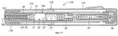
Фиг. 11 - вид с продольным разрезом устройства на фиг. 10, хранящимся в переносном футляре по этому изобретению. FIG. 11 is a longitudinal sectional view of the device of FIG. 10 stored in the portable case of this invention.
Фиг. 12 - увеличенный вид с частичным продольным разрезом инъектора, сходного с устройством на фиг. 11, но имеющего видоизмененную форму. Инъектор показан более подробно с переносным футляром и видоизмененным съемником оболочки. FIG. 12 is an enlarged view in partial longitudinal section of an injector similar to the device of FIG. 11, but having a modified shape. The injector is shown in more detail with a portable case and a modified shell remover.
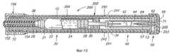
Фиг. 13 - вид с продольным разрезом устройства по еще одному варианту осуществления этого изобретения, имеющему пускатель. FIG. 13 is a longitudinal sectional view of a device according to yet another embodiment of this invention having a starter.
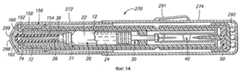
Фиг. 14 - вид с продольным разрезом устройства на фиг. 13, хранящемуся в переносном футляре по этому изобретению. FIG. 14 is a longitudinal sectional view of the device of FIG. 13 stored in the portable case of this invention.
Фиг. 15 - вид с продольным разрезом альтернативного патрона, изготовленного в соответствии с этим изобретением. FIG. 15 is a longitudinal sectional view of an alternative cartridge made in accordance with this invention.
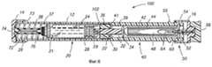
На фиг. 1 показано перезаряжаемое автоматическое инъекционное устройство 10 согласно этому изобретению. Инъекционное устройство или "инъектор" имеет удлиненный корпус или цилиндр 12, который простирается между первым, дистальным или концевым колпачком 14 и вторым, проксимальным или спусковым концевым колпачком 16. Цилиндр 12 представляет собой по существу цилиндрическую полую трубку, и предпочтительно изготавливается из твердого, долговечного материала, как например, металла или пластмассы. Концевые колпачки 14 и 16 подобным же образом изготавливают из твердого, долговечного материала. Цилиндр 12 имеет удлиненное, продольно расположенное окошко 18, образованное в нем для обеспечения возможности визуального доступа внутрь трубки. Окошко 18 может быть открытым и без какого-либо материала или предпочтительно состоять из прозрачного материала, как например, прозрачной пластмассы. In FIG. 1 shows a rechargeable
На фиг. 2 и 3 устройство 10 показано более подробно. Устройство 10 сконструировано с возможностью размещения в нем заменяемого шприцевого узла 20 однократного пользования. Главной частью этого узла 20 является патрон 21 с лекарственным средством. Патрон 21 содержит в себе ампулу или сосуд 22 для помещения и содержания жидкого лекарственного средства 24. Ампулой 22 предпочтительно является небольшой стеклянный или пластмассовый пузырек, который содержит измеренное количество лекарственного средства. Количество лекарственного средства (как например, противоядия, антибиотиков, адреналина, инсулина и т.д.) варьируется в зависимости от вида лекарственного средства и предлагаемых условиях его использования. Патрон 21 также имеет иглу 26 для подкожных инъекций, установленную на дистальном конце ампулы 22 с использованием колпачка 27 для крепления иглы. Патрон 21 имеет также непроницаемый для жидкости поршень, который представляет собой пробку 28, плотно посаженную и скользящую внутри ампулы 22. Пробка 28 предпочтительно изготовлена из резины или эластомерного материала, и имеет соединительную деталь в виде закрепленного штифта или снабженного резьбой выступа 29. Соединительная деталь поршня обращена наружу и, как показано, выступает наружу из пробки 28. Патрон 21 имеет общеизвестную конструкцию и имеется в продаже. Примерами предпочтительных патронов этой конструкции являются патроны, изготавливаемые компанией "Вайф Лэборэтэри, Инк" под товарным знаком "ТУБЕКС" и компанией "Элькинс-Синн" под товарным знаком "ДОЗЕТТЕ". In FIG. 2 and 3,
Поршень шприцевого узла имеет также съемный шток 30. Этот шток 30 поршня разъемного соединения с пробкой 28, с использованием подходящего разъемного соединения в штоке поршня. Хотя и предпочитается соединение, снабженное резьбой, могут быть применены и другие обычные способы обеспечения разъемного соединения между штоком 30 поршня и пробкой 28. Как показано, соединение содержит снабженный резьбой выступ 29, входящий в снабженное резьбой гнездо, образованное во внутреннем конце штока поршня. Шток 30 поршня включает в себя стержень 32 и головку штока, образованную в виде упорного диска или фланца 34. Шток 30 поршня предпочтительно изготавливают из жесткого материала, как например, пластмассы или металла. The piston of the syringe assembly also has a
Шприцевой узел 20 предпочтительно включает в себя также защитную оболочку 76, расположенную внутри цилиндра 12 вокруг иглы 26 патрона 21. Кончик иглы 26 немного заделан в головку оболочки для защиты острия и герметического закрывания отверстия иглы во избежание попадания загрязнений. Головка оболочки имеет фланец 78, входящий в гнездо 79 колпачка 14. Оболочка имеет трубчатую часть, которая простирается от головки и служит для помещения ниппеля 130 колпачка 27 иглы. Таким образом, оболочка 76 образует защитный изолирующий колпачок, который сохраняет стерильность иглы до ее использования. Шприцевой узел 20 не дорог в изготовлении и подлежит выбрасыванию после введения лекарственного средства 24 в пользователя. The
Согласно изобретению перезаряжаемое инъекционное устройство предназначено для автоматического использования и опорожнения патрона 21. Однако в случае неисправности устройства пользователь все еще может сделать инъекцию вручную, используя съемный шприцевой узел 20. Шприцевой узел 20 может быть легко вынут из инъекционного устройства 10 и может действовать в качестве самостоятельного управляемого вручную шприца в том случае, когда инъектор поврежден и не сработает. Эта сторона изобретения обладает преимуществом по сравнению с известными инъекторами, которые полностью заключены в оболочку и не позволяют иметь доступ к внутренней капсуле с лекарственным средством или удалять ее. According to the invention, the rechargeable injection device is designed to automatically use and empty the
Цилиндр 12 перезаряжаемого инъекционного устройства 10 имеет трубчатую форму и ограничивает внутреннюю полость 36 с первой или патронной камерой 37, имеющей достаточные размеры для помещения шприцевого узла 20, и с примыкающей второй камерой или камерой 39 выталкивателя. В предпочтительном варианте камера 37 имеет круглое поперечное сечение с диаметром несколько больше диаметра капсулы 22, с тем чтобы шприцевой узел мог легко передвигаться внутри полости 36 из первого положения или положения хранения, показанного на фиг. 2, во второе или разблокированное положение, показанное на фиг. 3. Патронная камера 37 несколько больше по поперечному сечению, чем вторая камера 39. Предпочтительно, чтобы камера 37 сводилась на конус у камеры 39, тем самым образуя конический заплечик 41. The
Автоматическое инъекционное устройство 10 содержит также выталкиватель 40 для введения иглы и вытеснения лекарственного средства из патрона. Выталкиватель 40 удерживается во взведенном положении и может быть управляемым образом высвобожден под действием его спускного механизма 50. Устройство также содержит вспомогательную или отжимную пружину 38, которая отжимает шприцевой узел 20 от дульного конца. Шприцевой узел предпочтительно отжат к заплечику 41, с тем чтобы лучше защищать иглу 26 от нечаянного выстреливания. Заплечик 41 также предотвращает смещение этого узла в направлении к выталкивателю относительно поршня и преждевременный выброс жидкости внутри цилиндра, например, при случайном падении устройства. Отжимная пружина 38 действует также в качестве подвески и амортизатора, чтобы вместе с оболочкой 76 обеспечивать безопасность хранения шприцевого узла в трубчатом футляре во время транспортировки и при условиях, которые могут вызвать перемещение или дребезжание этого узла. The
Выталкиватель 40 включает в себя продольный стержень 42, который может передвигаться в полости 36 цилиндра 12 между взведенным положением (фиг. 2) и одним или большим числом выдвинутых положений (фиг. 3). Выталкиватель 40 имеет также главную или выталкивающую пружину 44 для смещения и выталкивания стержня 42 в направлении к выдвинутому положению. Стержень 42 выталкивателя предпочтительно является жесткой деталью, изготовленной из пластмассы или металла, и расположен в цилиндре 12 вдоль его оси. Стержень 42 имеет боек или контактную головку 46, которая упирается в упорный диск 34 поршня во взведенном положении, и хвостовую часть 48. Головка 46 образует также заплечик, в который упирается выталкивающая пружина. Выталкивающая пружина 44 установлена соосно шприцевому узлу и намотана вокруг стержня 42. Когда выталкиватель 40 находится во взведенном положении, он расположен внутри камеры 39 полости 38 цилиндра. The
Спусковой механизм 50 выталкивателя удерживает выталкиватель 40 во взведенном положении, пока пользователь не будет готов к осуществлению инъекции. Спусковой механизм 50 включает в себя захват 52 и пускатель 54 для высвобождения захвата при приведении в действие или нажатии на пускатель. Спусковой механизм выталкивателя включает в себя также предохранитель для предотвращения срабатывания пускателя и высвобождения захвата. Пускатель 54 выполнен в виде концевого колпачка 16 и способен перемещаться относительно цилиндра 12 из положения покоя или выдвинутого положения в нажатое положение, в котором он упирается в кольцевой выступ 44 на наружной поверхности цилиндра 12. Пускатель 54 приводит в действие устройство при своем движении между положением покоя и нажатым положением. The
На фиг. 4 и 5 более подробно показан спусковой механизм 50 выталкивателя. Захват 52 представляет собой защелкивающий механизм для разъемного соединения выталкивателя с его спусковым механизмом. Защелкивающий механизм захвата 52 состоит из стреловидных или зазубренных наконечников 62 на многочисленных зубцах 64 (выполненных на хвостовой части 48 стержня 42). Зубцы пропущены через отверстие 58 захвата и защелкнуты за торцевую стенку 60 цилиндра 12. Торцевая стенка 60 предпочтительно выполнена в виде металлического круглого диска, заделанного в пластмассовый цилиндр 12, но она может быть в виде пластмассовой торцевой детали, формованной за одно целое с цилиндром 12. Зубцы 64 изготовлены с возможностью изгибаться из нормального, радиально раздвинутого положения, показанного на фиг. 4, в радиально сжатое положение, показанное на фиг. 5, чтобы наконечники 62 могли быть пропущены через отверстие 58. Как объяснено ниже, зубцы под действием пускателя 54 могут быть контролируемым образом согнуты в сжатое положение. In FIG. 4 and 5 show in more detail the
Через отверстие 58 в центральную часть между многочисленными зубками 64 вставлен предохранительный штифт 56 для удержания зубцов в их раздвинутом положении, с тем чтобы наконечники оставались захваченными позади торцевой стенки 60. Предохранительный штифт 56 можно вынимать из устройства 10 в направлении, показанном стрелкой 66 (фиг. 4). Предохранительный штифт 56 имеет соответствующее соединение с пускателем 54, чтобы предотвратить преждевременное выпадение предохранителя с конца устройства, допуская при этом его отделение вручную. Through the
Пускатель 54 нажимают или приводят в действие посредством внешнего усилия (как например, нажатием большого пальца пользователя) в направлении, показанном стрелками 68 на фиг. 5. Пускатель 54 имеет надавливающий элемент 70, который при нажатии на пускатель движется вперед и входит в соприкосновение с наружными наклонными поверхностями на наконечниках 62. Надавливающий элемент предпочтительно имеет скошенную внутреннюю поверхность, которая является сопряженной по отношению к наклонным поверхностям наконечников 62. Надавливающие элементы 70 сжимают наконечники до тех пор, пока они не отсоединяются от торцевой стенки 62 и не выйдут через отверстие 58. В этот момент высвобождается выталкиватель 40, и выталкивающая пружина 44 двигает выталкиватель по цилиндру 12, чтобы после этого разблокировать иглу и ввести ее с последующим выпуском лекарственного средства через введенную иглу. The
Возвращаемая к фиг. 2 и 3, на которых левый концевой колпачок 14 разъемно соединен с цилиндром 12, чтобы можно было вставлять и извлекать шприцевой узел 20. В предпочтительном варианте съемный колпачок 14 и дульный конец 72 цилиндра снабжены взаимно дополняющими резьбами, с тем чтобы съемный колпачок 14 можно было навинтить на цилиндр 12, хотя могут быть применены и другие соединительные приспособления. Колпачок 14 можно накручивать на цилиндр 12, пока он не достигнет кольцевого выступа 73, образованного на наружной поверхности цилиндра 12. Колпачок 14 закрывает полость 36 при соединении с цилиндром 12 и, наоборот, открывает полость при снятии с цилиндра, позволяя извлечь шприцевой узел. В съемном колпачке 14 образовано отверстие или проход 74 для иглы, через который может выступать игла 26 патрона 21, когда пользователем приводится в действие инъекционное устройство 10 и происходит срабатывание шприцевого узла (фиг. 3). Returning to FIG. 2 and 3, on which the
Оболочка 76 закрывает отверстие 74 для предотвращения загрязнения иглы 26. Оболочку 76 предпочтительно изготавливают из деформирующегося материала, например резины, который может изгибаться под действием усилия выталкивающей пружины 44 выталкивателя 40, как это показано на фиг. 3. Отбортованная часть оболочки 76 упирается во внутреннюю поверхность колпачка 14, и головка оболочки прокаливается иглой 26, шприцевой узел посредством выталкивателя перемещается по цилиндру. Колпачок 14 имеет ступенчатую внутреннюю поверхность для размещения отжимной пружины 38 и отбортованной части оболочки 76. The
Теперь со ссылкой на фиг. 2 и 3 будет описан принцип действия этого изобретения. После изготовления пустое инъекционное устройство пригодно для хранения длительный период времени. Индивидуальные шприцевые узлы, содержащие различные виды лекарственных средств, изготавливают и хранят отдельно в соответствии с обозначенными сроками годности. Если срок хранения лекарственного средства в шприцевом узле превышает срок годности, то можно выбросить отдельный шприцевой узел. Способ изготовления шприцевых узлов заключается в простом модифицировании существующих патронов, как например, патронов "ТУБЕКС" и "ДОЗЕТТЕ", снабдив их оболочкой и съемным поршнем, как это описано здесь. В этом случае пользователь может вручную делать инъекцию, используя шприцевой узел. Это делается путем удаления оболочки, введения иглы и нажатия вручную на поршень обычным образом. Now with reference to FIG. 2 and 3, the principle of operation of this invention will be described. After manufacture, the empty injection device is suitable for storage for a long period of time. Individual syringe assemblies containing various types of medicines are made and stored separately in accordance with the indicated expiration dates. If the shelf life of the drug in the syringe unit exceeds the expiration date, you can discard a separate syringe unit. A method for manufacturing syringe assemblies consists in simply modifying existing cartridges, such as TUBEX and DOSETTE cartridges, providing them with a shell and a removable piston, as described here. In this case, the user can manually inject using the syringe unit. This is done by removing the sheath, inserting the needle and manually pressing the piston in the usual way.
При автоматическом способе инъекции автоматическое инъекционное устройство перед временем его прогнозируемого возможного использования заряжают необходимым шприцевым узлом с выбранным лекарственным средством. Вначале удаляют колпачок 14 с дульного конца 72 цилиндра 12. Если устройство не взведено, то тогда можно вставить в полость подходящий стержень и отжать выталкиватель во взведенное положение на фиг. 2. Затем может быть вставлен предохранитель 56. После этого через дульный конец вставляют шприцевой узел 20 в цилиндр 12 и ориентируют его в нем так, чтобы защищенная оболочкой игла была направлена наружу к дульному концу. Надевают отжимную пружину 38 на оболочку 76 и вновь навинчивают колпачок 14 на цилиндр. В этом состоянии устройство 10 находится во взведенном положении с шприцевым узлом, безопасно отведенном внутри цилиндра, как этого показано на фиг. 2. Теперь устройство 10 заряжено и готового к использованию. With the automatic injection method, the automatic injection device is charged with the necessary syringe unit with the selected drug before the time of its predicted possible use. First,
Окошко 18 в цилиндре 12 позволяет пользователю видеть патрон и лекарственное средство. По этой визуальной проверке пользователь может быстро определить относительное положение поршня, уровень дозы и то, стало ли лекарственное средство испорченным (например, определяемое по его помутнению или изменению цвета). The window 18 in the
Для приведения устройства 10 в действие снимают предохранитель 56 и нажимают на пускатель 54 для освобождения захвата 52. Высвобождается энергия, запасенная выталкивающей пружиной 44 выталкивателя 40, которая заставляет шприцевой узел 20 двигаться по цилиндру 12. Игла 26 прокалывает головку оболочки 76 и выталкивается наружу через отверстие 74 в колпачке 14. Одновременно под действием усилия выталкивающей пружины 44 сплющивается трубчатая часть оболочки 76 и сжимается вспомогательная пружина 38. Шприцевой узел 20 останавливается, когда он достигает конца цилиндра после перемещения на полезное расстояние, обеспечивающее надлежащее введение обнаженной иглы в ткань пользователя. Полностью сжатая вспомогательная пружина 38 действует в качестве упора для ампулы 22 или колпачка 27 иглы. To actuate the
После перемещения шприцевого узла в положение инъекции продолжает действовать толкающая сила выталкивателя 40, которая давит на поршень 30. Это приводит к передвижению поршня 28 патрона и вытеснению жидкого лекарственного средства через иглу 26 для подкожных инъекций. Поршень опускается до тех пор, пока упорный диск 34 не соприкоснется с концом ампулы 22 или же пока не остановится. Устройство и патроны сконструированы таким образом, чтобы длина хода поршня была точной для инъекции заданной дозы лекарственного средства. After moving the syringe assembly to the injection position, the pushing force of the
После завершения инъекции пользователь может удалить устройство и иглу. Использованное устройство затем можно вновь зарядить. Для этого просто снимают колпачок 14, после чего удаляют и выбрасывают использованный шприцевой узел. Вновь взводят выталкиватель 40, вставляя тонкий инструмент (как например, отвертку, ручки или карандаш) в цилиндр, и толкая стержень 42 против усилия пружины 44 до тех пор, пока зазубренные наконечники не сожмутся и не пройдут через отверстие 58, а затем не разожмутся для закрепления позади стенки 62 (фиг. 4). В этот момент можно вновь вставить предохранитель 56 для предотвращения нежелательного срабатывания устройства. Затем можно вставить в цилиндр новый шприцевой узел, содержащий одинаковое или иное лекарственное средство, и вновь присоединить колпачок. After the injection is completed, the user can remove the device and the needle. The used device can then be recharged. To do this, simply remove the
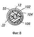
На фиг. 6 - 8 показано перезаряжаемое инъекционное устройство 100 согласно другому предпочтительному варианту осуществления изобретения. Устройство 100 предназначено для выполнения многократных (обычно двух) инъекций с использованием одного и того же шприцевого узла. Устройство 100 очень похоже на устройство 10 на фиг. 2 - 5, и для обозначения сходных деталей используются одинаковые цифры. Подробно будут описаны только отличительные особенности этого устройства. In FIG. 6 to 8 show a
Устройство 100 включает в себя съемный стопор 102 для остановки движения выталкивателя в выдвинутом положении после его высвобождения. Стопор 102 находится внутри цилиндра 12 и расположен по крайней мере частично вокруг поршневого штока 32 шприцевого узла 20. Стопор 102 имеет такой радиальный размер, чтобы упираться в торец ампулы 22, и также заранее определенную длину, чтобы при одном и том же шприцевом узле обеспечивать приблизительно равные дозы для каждой инъекции. В своем предпочтительном варианте съемный стопор 102 состоит из первой и второй полуцилиндрических кольцевых частей 104, расположенных вокруг штока 32 поршня (фиг. 8). The
При использовании устройство 100 заряжают шприцевым узлом и выбивают или выстреливают по существу так, как описано выше. Однако в этом варианте осуществления изобретения стопор 102 останавливает движение поршня 30 до того, как будет полностью вытеснено лекарственное средство из ампулы 22. Конкретнее, упорный диск 34 поршня 30 перемещается до тех пор, пока он не соприкаснется с кольцевыми частями 104 и 106. Это частичное перемещение поршня 30 соответствует инъекции первой дозы лекарственного средства. Если пользователь желает сделать вторую инъекцию с использованием оставшегося лекарственного средства, то он может просто снять колпачок 14 и вынуть шприцевой узел из цилиндра. Это позволяет удалить разрезное кольцо, которое легко вынимается благодаря его разрезной конструкции. Затем вновь взводят инъектор нажатием на выталкиватель 40. Частично опорожненный шприцевой узел вновь помещают в цилиндр и опять устанавливают концевой колпачок 14. При удаленном стопоре 102 устройство 100 теперь по существу одинаково с устройством 10 и готово для своего второго приведения в действие. Когда приводится в действие выталкиватель 50, поршень дальше вдавливается в ампулу 22 для вытеснения оставшегося жидкого лекарственного средства через иглу 26. In use,
Благодаря такой конструкции перезаряжаемого инъекционного устройства 100 пользователь по выбору может ввести вторую дозу вручную без повторного взведения и заряжения устройства. Пользователь может просто вынуть шприцевой узел из устройства, снять стопорные кольца и вручную ввести лекарственное средство, используя шприцевой узел. Это очень полезно в условиях оказания неотложной помощи, когда время имеет решающее значение и не может тратиться на повторное взведение и заряжение устройства. Подобным же образом может быть открыто устройство и по варианту 10, и по варианту 100 и извлечен шприцевой узел для возможности выполнения инъекции вручную. Это может потребоваться из-за механических затруднений или по другим причинам. Due to this design of the
Следует также учесть, что новое устройство согласно этому изобретению может применяться для уменьшения или устранения потери ценных лекарственных средств. Такие лекарственные средства прежде терялись при использовании в инъекторах для неотложной помощи. Это происходит вследствие их порчи со временем и того факта, что лекарственное средство закупорено внутри инъектора. Для предотвращения таких потерь настоящее изобретение можно применять любым из двух способов. Во-первых, лекарственные средства могут быть помещены в устройство только при необходимости в них и могут быть взяты из обычных запасов. Во-вторых, лекарственные средства, используемые в новых инъекторах, могут помещены в них и затем удалены в соответствующее время, чтобы позволить больнице или другой медицинской службе использовать их в обычном курсе оказания услуг, таким образом предотвращая потерю патрона из-за порчи лекарственного средства со временем. Инъектор не теряется лишь из-за старения лекарственного средства и может продолжить служить в качестве запасного или быть перезаряженным. It should also be noted that the new device according to this invention can be used to reduce or eliminate the loss of valuable drugs. Such medicines were previously lost when used in injectors for emergency care. This is due to their deterioration over time and the fact that the drug is clogged inside the injector. To prevent such losses, the present invention can be applied in any of two ways. Firstly, medicines can only be placed on the device if necessary and can be taken from ordinary supplies. Secondly, the drugs used in the new injectors can be placed in them and then removed at the appropriate time to allow the hospital or other medical service to use them in the normal course of service, thus preventing cartridge loss due to drug damage time. The injector is not lost just because of the aging of the drug and can continue to serve as a spare or be recharged.
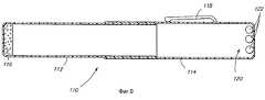
На фиг. 9 показан предпочтительный переносной футляр 110, который может быть использован с инъекционными устройствами по этому изобретению. Футляр 110 может такие размеры, чтобы вмещать в себя устройства 10 или 100. Футляр 110 имеет первую и вторую половины 112 и 114, которые плотно сцеплены друг с другом с образованием полого, трубчатого корпуса. Первая половина 112 имеет пенопластовую подкладку 116, расположенную на ее конце с образованием амортизирующей подушки, которая помогает предотвратить дребезжание или перемещение устройства внутри футляра. К наружной поверхности футляра 110 прикреплен зажим 118, который похож на зажимы шариковых ручек и подобно им пригоден для прикрепления футляра 110 к карману рубашки или т.п. Футляр 110 имеет также углубления 120 для хранения таблеток 122, как например, пероральные антигистаминные средства. In FIG. 9 shows a preferred
На фиг. 10 показано перезаряжаемое инъекционное устройство 150 согласно еще одному предпочтительному варианту осуществления этого изобретения. Устройство 150 очень похоже на устройство 10 на фиг. 2 - 5, поэтому будут описаны подробно только отличительные особенности. In FIG. 10 shows a
Инъекционное устройство 150 имеет видоизмененный дистальный, дульный концевой колпачок 152, который посредством резьбы может быть присоединен к дульному концу 72 цилиндра 12. Видоизмененный концевой колпачок 152 изготовлен с образованным в нем отверстием 74 для иглы, через который может выступать игла при инъекции. Устройство 150 имеет защитную оболочку 154, предусмотренную на игле 26. Оболочка 154 защищает иглу 26 и сохраняет ее стерильность. Оболочку предпочтительно изготавливают из пластмассы или резины. Она имеет такие размеры, чтобы проходить через отверстие 74 для иглы в концевом колпачке 152. The
Инъектор 150 включает в себя также съемник 156 оболочки для сцепления с защитной оболочкой 154 и удаления ее с иглы 26. Съемник 156 оболочки разъемно соединен с дульным концом 72 цилиндра 12. Съемник 156 оболочки предпочтительно состоит из трубчатой части 158, которая открыта с одного конца, и торцевой стенки 160. Трубчатая часть 158 имеет внутренний диаметр, который приблизительно равен наружному диаметру концевого колпачка 152, так что можно плотно установить съемник 156 оболочки, надевая его на концевой колпачок 152 у дульного конца 72. Можно также использовать другие виды соединений, как например соединения, снабженные резьбой. Съемник оболочки предпочтительно изготавливает из твердого, долговечного материала, как например, пластмассы или металла. The
Съемник 156 оболочки имеет зажимное отверстие 162, образованное в торцевой стенке 160. Отверстие 162 имеет такие размеры, чтобы вмещать и плотно зажимать защитную оболочку 154. Когда съемник 156 оболочки снимают с инъекционного устройства 150, зажимное отверстие 162 захватывает оболочку 154 для ее одновременного удаления и обнажения иглы 26 для инъекции. Съемник оболочки по выбору можно снабдить зубцами (см. фиг. 12) вокруг отверстия 162 для зацепления съемника с оболочкой. Эта альтернативная конструкция предпочитается при использовании резиновой оболочки. The
На фиг. 11 показано инъекционное устройство 150 в защитном переносном футляре 170, изготовленном согласно другой стороне этого изобретения. Переносный футляр 170 представляет собой полое, по существу трубчатое изделие и размерами, позволяющими поместить устройство 150 в футляр. Футляр 170 состоит из передней или нижней части 172 и задней или верхней части 174. Части 172 и 174 можно разъединить вручную, чтобы можно было извлечь инъекционное устройство 150. После удаления верхней части 174 инъектор обычно будет находиться в нижней части. Передняя и задняя части футляра имеют соединение 176 с плотной посадкой для удержания обоих частей вместе с разъединяемым вручную футляре. In FIG. 11 shows an
Футляр 170 включает в себя также держатель 178 съемника оболочки. Этот держатель 178 плотно сцеплен со съемником 156 оболочки, например, благодаря точному выбору размеров взаимодополняющих поверхностей или образованием между ними посадки с незначительным натягом. Держатель 178 сцеплен со съемником 156 оболочки и удерживает его, с тем чтобы защитная оболочка 154 автоматически удалялась с иглы, когда инъектор вынимают из нижней части 172 футляра. Таким образом, инъектор сразу же оказывается готовым для снятия предохранителя и для приведения устройства в действие, тем самым устраняя дополнительную стадию удаления оболочки. Футляр по выбору можно изготовить без держателя для съемника оболочки, а съемник 156 оболочки и сцепленную с ним оболочку 154 можно удалят вручную после извлечения инъектора из футляра. The
На фиг. 12 показан увеличенный вид дульного конца заключенного в футляр инъекционного устройства и подробнее изображен альтернативный съемник оболочки зажимного типа. Съемник оболочки содержит зазубренный зажим 180, который прочно зажимает оболочку 154. Зажим 180 позволяет легко вставлять оболочку 154 в него, но препятствует удалению оболочки из него. Таким образом, зажим 180 легко надевается на оболочку 154, когда съемник 156 оболочки устанавливают на цилиндр 12 инъектора. Однако при извлечении инъектора 150 из футляра 170 зажим захватывает оболочку для ее удаления одновременно со снятием части 172 футляра с дульного конца цилиндра 12. In FIG. 12 is an enlarged view of the muzzle end of an injection device enclosed in a case, and an alternate clamp-type shell remover is shown in more detail. The sheath puller comprises a
В предпочтительной конструкции зажим 180 является однонаправленным зажимом, который позволяет легко вставлять оболочку в первом направлении при надевании части 172 футляра на инъектор, но препятствует извлечению оболочки во втором противоположном направлении, когда с инъектора снимают эту часть футляра. Зажим 180 содержит многочисленные изгибающиеся выступы 182 (например, четыре выступа), имеющие зазубренные захваты 184 на своих внутренних концах. Зазубренные захваты имеют наклонные поверхности 186, которые облегчают вставление оболочки, и направленные внутрь острые концы, которые захватывают оболочку после ее вставления в зажим. Альтернативно выступы могут быть преобразованы в круглое кольцо или козырек (не показан), которые при виде в разрезе выглядел бы одинаковым или похожим на зазубренные выступы на фиг. 12. In a preferred design, the
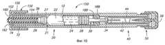
На фиг. 13 показано перезаряжаемое инъекционное устройство 200 согласно еще одному предпочтительному варианту осуществления этого изобретения. Устройство 200 похоже на устройство 10 на фиг. 2 - 5 и устройство 150 на фиг. 10. Однако в отличие от этих более ранних вариантов инъектор 200 имеет пускатель 202, соединенный со спусковым механизмом 50 выталкивателя. Пускатель 202 предпочтительно выполнен в форме трубки, которая образует наружный корпус инъектора. Его полезно изготавливать в виде цилиндрической трубки, несколько большей и диаметральном размере, чем цилиндр 12, и способной передвигаться по нему. In FIG. 13 shows a
Верхний конец пускателя предпочтительно снабжен торцевой стенкой 203 с отверстием 205, через которое выступает предохранительный штифт 57 предохранителя 56. Отверстие 205 служит также в качестве спускового отверстия благодаря сжимающим поверхностям 71, которые касаются и сжимают кончики 62 снабженного выступами захвата выталкивателя. После удаления предохранителя 56 пускатель можно перемещать из положения неиспользования устройства в положение его пуска в действие, передвигая пускатель 202 влево на фиг. 13 относительно цилиндра 12. Таким образом, при передвижении пускателя в положение пуска устройства в действие спусковой механизм 50 высвобождает выталкиватель 40. The upper end of the starter is preferably provided with an
Пускатель 202 включает в себя надеваемую вручную трубку 204, которая установлена на цилиндре 12 и перемещается по нему. Трубка 202 передвигается относительно цилиндра 12 из положения неиспользования устройства или несрабатывания спускового механизма в положение использования устройства или срабатывания спускового механизма. Предпочитается, чтобы трубка 204 значительно простиралась вдоль цилиндра 12 от его проксимального конца 13 к его дистальному, дульному концу 72. Трубка предпочтительно простирается по крайней мере на 75% длины цилиндра до места, примыкающего к концевому колпачку 152. Более предпочтительно, чтобы трубка простиралась на длину, достаточную для того, чтобы соприкасаться с обращенным внутрь краем съемника 156 оболочки, кода устройство находится в заряженном, а не в использованном положении. Такое соприкосновение имеет предохранительное значение, ограничивая продольное движение трубки пускателя во взведенном положении до тех пор, пока с дульного конца инъектора не будут удалены съемник оболочки и сама оболочка. Таким образом, если даже и удален предохранитель, инъектор в большинстве случаев может быть приведен в действие только после удаления оболочки и съемник оболочки. В показанной конструкции съемник оболочки тем самым действует в качестве второго предохранителя.
На фиг. 13 показано также, что цилиндр 12 и пускатель 202 можно изготовить так, чтобы удерживать пускатель на цилиндре и обеспечивать механическое взаимосцепление между ними. Эти функции в сочетании успешно обеспечиваются с помощью одного или большего числа держателей на цилиндре, которые находятся в сцеплении с пускателем. Как показано, цилиндр снабжен двумя взаимодополняющими удерживающими выступами 242, которые входят в прорези 241. Удерживающие выступы 242 предпочтительно снабжены нижней поверхностью, которая расположена поперек продольной оси инъектора. Верхняя поверхность предпочтительно наклонена, образуя часть конической поверхности. Эти наклоннные верхние поверхности служат для облегчения установки пускателя на цилиндр путем вставления цилиндра в дульный конец пускателя и деформации соответствующих частей на достаточную величину, чтобы выступы точно совпали с принимающими их прорезями 241. In FIG. 13 also shows that the
Прорези 241 образованы в стенке пускателя или проходят через нее. Когда инъектор находится в зараженном состоянии и не введен в действие, нижние поверхности выступов опираются на нижние концы прорезей 241. После удаления предохранителя 56 можно затем опустить пускатель 204 для его передвижения относительно цилиндра. The
Выступы 242 и прорези 241 обеспечивают также механическое взаимосцепление между пускателем и цилиндром. Конкретное, это сцепление предотвращает чрезмерное продольное движение. Оно также предотвращает вращательное движение между цилиндром и пускателем. Эта возможность предотвращать вращение позволяет крутить концевой колпачок 152 относительно цилиндра, одновременно удерживая пускатель. Это относительное кручение необходимо для удаления концевого колпачка с цилиндра и установки на него, например, при использовании устройства вручную для оказания неотложной помощи, или при заряжении или разряжении инъектора. Эта конструкция позволяет также более эффективно использовать пускатель в качестве захватываемой рукой части устройства, через которую можно передавать усилие как при введении иглы в человека, подвергающегося инъекции, так и при выведении иглы из него. The
Цилиндр и пускатель наиболее предпочтительно изготавливать из прозрачного материала, например, из прозрачной пластмассы. Эта конструкция позволяет пользователю заглядывать внутрь инъектора для определения того, имеется ли патрон в инъекторе. Она также позволяет пользователю определять, стало ли непригодным лекарственное средство в ампуле, на что может указывать его обесцвечивание или помутнение. The cylinder and starter are most preferably made from a transparent material, for example, from a transparent plastic. This design allows the user to look inside the injector to determine if there is a cartridge in the injector. It also allows the user to determine whether the drug in the ampoule has become unusable, as indicated by discoloration or turbidity.
Для приведения инъектора 200 в действие пользователь вначале отделяет съемник 156 оболочки, тем самым одновременно удаляя оболочку 154. Пользователь затем удаляет предохранитель 56 для приведения инъектора в состояние готовности, зажимает пускатель 202 в руке и вводит лекарственное средство быстрым движением руки, при котором дульный конец 72 ударяется о тело пользователя в желаемом месте инъекции. Цилиндр остановится при соприкосновении с пользователем, а пускатель будет продолжать двигаться, высвобождая выталкиватель 40. Под действием усилия главной пружины 44 выталкиватель 40 вводит иглу 24 шприцевого узла 20 в ткань пользователя и выдает надлежащую дозу лекарственного средства 24. To bring the
Пускатель облегчает введение лекарственного средства благодаря легкости захватывания и перемещения пускателя. Это особенно полезно для пользователей, которые находятся в ослабленном состоянии и в меньшей степени способны привести в действие более требовательный "пальцевый" пускатель, описанный выше. The starter facilitates the administration of the drug due to the ease of gripping and moving the starter. This is especially useful for users who are in a weakened state and are less able to actuate the more demanding “finger” starter described above.
Следует отметить, что варианты осуществления изобретения, показанные на фиг. 10 и 13, наиболее предпочтительно оснащать стопорным устройством, которое регулирует и ограничивает перемещение поршня шприца. Как показано на фиг. 10, в стопорном устройстве используют первый стопор 188 и второй стопор 189. Первый стопор 188 является съемным стопором, предпочтительно образованным взаимодополняющими полукольцами, которые расположены вокруг штока поршня. Верхний торец первого стопора входит в соприкосновение с головкой 34 поршня. Этот стопор определяет количество лекарственного средства, вводимого в первой дозе. Разрезное кольцо 188 удаляют, снимая дульный колпачок 152 и извлекая шприцевой узел из цилиндра 12. После удаления разрезного кольца второй стопор 189 служит для остановки поршня при введении второй дозы. Головка 34 поршня соприкасается со вторым стопором 189. Второй стопор полезно выполнять в виде неизвлекаемой кольцевой детали, удерживаемой на штоке поршня. Второй стопор 189 позволяет хорошо контролировать объем второй вводимой дозы. It should be noted that the embodiments of the invention shown in FIG. 10 and 13, it is most preferable to equip with a locking device that controls and restricts the movement of the plunger of the syringe. As shown in FIG. 10, a
Как показано на фиг. 14, изобретение касается также другого инъекционного устройства с футляром 270, похожим на футляр 170. Футляр 270 имеет верхнюю или первую часть 274, с размерами, обеспечивающими ее плотное сцепление с нижней или второй частью 272. На фиг. 13 футляр 270 показан с находящимся в нем инъектором 200. Крайний или нижний конец полезно снабжать углублением 298, в которое без заметного усилия помещается конец оболочки. В углублении 298 футляра 270 помещена также упругая подкладка 299 для конца оболочки. Футляр снабжен зажимом 291 для поддержки футляра в кармане пользователя. При желании футляр 270 может также содержать дополнительные лекарственные средства, как например, таблетки 292. As shown in FIG. 14, the invention also relates to another injection device with a
На фиг. 15 показан альтернативный патрон или шприцевой узел, который можно успешно использовать в инъекторах, изготовленных в соответствии с этим изобретением. Патрон на фиг. 15 имеет регулируемый шток 330 поршня, который полезно изготовить с использованием первой части 331 штока поршня. Она имеет первое соединение или соединение с поршнем, которое полезно выполнять в виде снабженного резьбой гнезда 332, в которое входит шпилька 29 на поршне шприца. Первая часть 331 штока поршня имеет также второе соединение или регулируемое соединение с головкой, которое полезно выполнять в виде снабженного резьбой гнезда 336 для головки штока. В это гнездо входит вторая часть 335 штока поршня, предпочтительно с возможностью регулирования в осевом направлении. Возможность регулирования в осевом направлении наиболее предпочтительно осуществляется с использованием резьбового соединения, которое позволяет ввинчивать головку в гнездо и вывинчивать из него для регулирования положения контактной головки 334. Эта конструкция может быть использована для регулирования и для изменений в длине шприца и положении поршня внутри ампулы. Головку 334 предпочтительно регулируют, используя измерительный прибор (не изображен), который показывает желаемое положение головки, и затем ввинчивая вторую часть 335 штока поршня для достижения желаемого положения головки. Стопор 188 полезно выбирать с длиной, приблизительно равной половине расстояния между стопором 189 и контактной поверхностью головки 334, когда содержание ампулы требуется вводить в виде двух приблизительно равных доз. In FIG. 15 shows an alternative cartridge or syringe assembly that can be successfully used in injectors made in accordance with this invention. The cartridge of FIG. 15 has an
Перезаряжаемое инъекционное устройство по этому изобретению полезно благодаря предоставляемой им максимальной гибкости в том, что можно легко и удобно осуществлять ручную или автоматическую инъекцию одинарной или многократной дозы лекарственного средства. Изобретение также повышает надежность устройства, так как в случае механического повреждения инъектора пользователь может иметь легкий доступ к инъекционному узлу, и вручную ввести лекарственное средство. Эти и другие преимущества и выгоды изобретения описаны или очевидны из приведенного здесь описания. The rechargeable injection device of this invention is useful due to its maximum flexibility in that it is easy and convenient to carry out manual or automatic injection of a single or multiple dose of the drug. The invention also improves the reliability of the device, since in the case of mechanical damage to the injector, the user can have easy access to the injection site and manually enter the drug. These and other advantages and benefits of the invention are described or apparent from the description herein.
Изобретения полезны в связи и инъекцией лекарственного средства и производством медицинских инъекционных устройств. The invention is useful in connection with both drug injection and the manufacture of medical injection devices.
Claims (15)
Translated fromRussianApplications Claiming Priority (7)
| Application Number | Priority Date | Filing Date | Title |
|---|---|---|---|
| US08/068,644US5358489A (en) | 1993-05-27 | 1993-05-27 | Reloadable automatic or manual emergency injection system |
| US08/068,644 | 1993-05-27 | ||
| US08/068.644 | 1993-05-27 | ||
| US08/243,641US5540664A (en) | 1993-05-27 | 1994-05-16 | Reloadable automatic or manual emergency injection system |
| US08/243,641 | 1994-05-16 | ||
| US08/243.641 | 1994-05-16 | ||
| PCT/US1994/005949WO1994027660A1 (en) | 1993-05-27 | 1994-05-26 | Reloadable automatic or manual emergency injection system |
Publications (2)
| Publication Number | Publication Date |
|---|---|
| RU95122674A RU95122674A (en) | 1998-02-10 |
| RU2131748C1true RU2131748C1 (en) | 1999-06-20 |
Family
ID=26749198
Family Applications (1)
| Application Number | Title | Priority Date | Filing Date |
|---|---|---|---|
| RU95122674ARU2131748C1 (en) | 1993-05-27 | 1994-05-26 | Automatic or manual device for injections of liquid medicinal agent |
Country Status (11)
| Country | Link |
|---|---|
| US (2) | US5540664A (en) |
| EP (1) | EP0700307B1 (en) |
| JP (1) | JPH08507239A (en) |
| AT (1) | ATE213424T1 (en) |
| AU (1) | AU683901B2 (en) |
| CA (1) | CA2163005C (en) |
| DE (1) | DE69429918T2 (en) |
| ES (1) | ES2173117T3 (en) |
| PL (1) | PL176380B1 (en) |
| RU (1) | RU2131748C1 (en) |
| WO (1) | WO1994027660A1 (en) |
Cited By (17)
| Publication number | Priority date | Publication date | Assignee | Title |
|---|---|---|---|---|
| RU2299723C2 (en)* | 2001-08-31 | 2007-05-27 | Ново Нордиск А/С | Ampulla for liquid insulin |
| RU2300396C2 (en)* | 2002-05-10 | 2007-06-10 | Кембридж Байостабилити Лтд | Single-use injector |
| RU2337719C2 (en)* | 2003-08-01 | 2008-11-10 | Шеринг Акциенгезелльшафт | Injector |
| RU2355430C2 (en)* | 2004-01-23 | 2009-05-20 | Зе Медикал Хаус Плк | Injection device |
| RU2387460C2 (en)* | 2004-06-23 | 2010-04-27 | Эбботт Биотекнолоджи Лимитед | Automatic injector |
| RU2401668C2 (en)* | 2007-10-23 | 2010-10-20 | Общество с ограниченной ответственностью Научно-производственное предприятие "АВАНГАРД-МТ" | Automatic injector |
| RU2405574C2 (en)* | 2006-05-10 | 2010-12-10 | Медрад, Инк. | Medical injector with front loading and syringes to be applied with it |
| RU2438721C2 (en)* | 2006-06-30 | 2012-01-10 | Эбботт Байотекнолоджи Лтд. | Automatic injection device |
| RU2493882C2 (en)* | 2007-01-27 | 2013-09-27 | Лтс Ломанн Терапи-Системе Аг | Disposable injector with at least one draw hook |
| RU2502527C2 (en)* | 2007-04-19 | 2013-12-27 | Лтс Ломанн Терапи-Системе Аг | Disposable injector with at least one pull bar and movable wedge mechanism for cocking release of locking elements |
| US8636704B2 (en) | 2009-04-29 | 2014-01-28 | Abbvie Biotechnology Ltd | Automatic injection device |
| US8679061B2 (en) | 2006-06-30 | 2014-03-25 | Abbvie Biotechnology Ltd | Automatic injection device |
| US8708968B2 (en) | 2011-01-24 | 2014-04-29 | Abbvie Biotechnology Ltd. | Removal of needle shields from syringes and automatic injection devices |
| US8758301B2 (en) | 2009-12-15 | 2014-06-24 | Abbvie Biotechnology Ltd | Firing button for automatic injection device |
| US9180244B2 (en) | 2010-04-21 | 2015-11-10 | Abbvie Biotechnology Ltd | Wearable automatic injection device for controlled delivery of therapeutic agents |
| US9265887B2 (en) | 2011-01-24 | 2016-02-23 | Abbvie Biotechnology Ltd. | Automatic injection devices having overmolded gripping surfaces |
| US10806867B2 (en) | 2011-01-24 | 2020-10-20 | E3D Agricultural Cooperative Association Ltd. | Injector |
Families Citing this family (285)
| Publication number | Priority date | Publication date | Assignee | Title |
|---|---|---|---|---|
| US5569189A (en)* | 1992-09-28 | 1996-10-29 | Equidyne Systems, Inc. | hypodermic jet injector |
| GB9412301D0 (en)* | 1994-06-17 | 1994-08-10 | Safe T Ltd | Hollow-needle drugs etc applicators |
| US5730723A (en) | 1995-10-10 | 1998-03-24 | Visionary Medical Products Corporation, Inc. | Gas pressured needle-less injection device and method |
| AU1860697A (en)* | 1995-09-08 | 1997-07-28 | Visionary Medical Products Corporation | Pen-type injector drive mechanism |
| US5658259A (en)* | 1995-10-19 | 1997-08-19 | Meridian Medical Technologies, Inc. | Dental cartridge assembly auto-injector with protective needle cover |
| US5709662A (en)* | 1996-08-23 | 1998-01-20 | Becton Dickinson France, S.A. | Cartridge for an injection device |
| AU7398096A (en)* | 1996-10-09 | 1998-05-05 | Equidyne Systems, Incorporated | Hypodermic jet injector |
| US6093172A (en)* | 1997-02-05 | 2000-07-25 | Minimed Inc. | Injector for a subcutaneous insertion set |
| US6607509B2 (en) | 1997-12-31 | 2003-08-19 | Medtronic Minimed, Inc. | Insertion device for an insertion set and method of using the same |
| US20070142776A9 (en)* | 1997-02-05 | 2007-06-21 | Medtronic Minimed, Inc. | Insertion device for an insertion set and method of using the same |
| US5851197A (en)* | 1997-02-05 | 1998-12-22 | Minimed Inc. | Injector for a subcutaneous infusion set |
| US6605058B1 (en) | 1997-11-17 | 2003-08-12 | Disetronic Licensing Ag | Device for introducing a needle |
| US6482176B1 (en) | 1997-11-27 | 2002-11-19 | Disetronic Licensing Ag | Method and device for controlling the introduction depth of an injection needle |
| WO1999030759A2 (en) | 1997-12-16 | 1999-06-24 | Meridian Medical Technologies, Inc. | Automatic injector for administrating a medicament |
| JP4194754B2 (en)* | 1998-01-12 | 2008-12-10 | モルソエ,クラウス | Syringe |
| US6290679B1 (en)* | 1999-05-14 | 2001-09-18 | Disetronic Licensing Ag | Device for metered administration of an injectable product |
| USD526409S1 (en) | 1998-07-14 | 2006-08-08 | Unomedical A/S | Medical puncturing device |
| US6664953B2 (en)* | 1998-08-06 | 2003-12-16 | Hewlett-Packard Development Company, L.P. | Method and receptacle for receiving and releasing a pen |
| WO2000029049A1 (en)* | 1998-11-13 | 2000-05-25 | Elan Pharma International Limited | Drug delivery systems and methods |
| DE29822494U1 (en)* | 1998-12-17 | 2000-05-04 | Medico Development Investment Co., Ascona | Injection device |
| DE19925904C1 (en) | 1999-06-07 | 2001-02-01 | Disetronic Licensing Ag | Unit for subcutaneous application of an injectable product comprises a system which indicates whether the protection sleeve of the injection needle is in its fully retracted position |
| EP1257307A2 (en) | 1999-09-13 | 2002-11-20 | Vitro Diagnostics, Inc. | Multi-dose syringe driver |
| US6569123B2 (en) | 1999-10-14 | 2003-05-27 | Becton, Dickinson And Company | Prefillable intradermal injector |
| US6569143B2 (en) | 1999-10-14 | 2003-05-27 | Becton, Dickinson And Company | Method of intradermally injecting substances |
| US6382204B1 (en)* | 1999-10-14 | 2002-05-07 | Becton Dickinson And Company | Drug delivery system including holder and drug container |
| US6494865B1 (en) | 1999-10-14 | 2002-12-17 | Becton Dickinson And Company | Intradermal delivery device including a needle assembly |
| US20020193740A1 (en) | 1999-10-14 | 2002-12-19 | Alchas Paul G. | Method of intradermally injecting substances |
| US6776776B2 (en)* | 1999-10-14 | 2004-08-17 | Becton, Dickinson And Company | Prefillable intradermal delivery device |
| US6843781B2 (en)* | 1999-10-14 | 2005-01-18 | Becton, Dickinson And Company | Intradermal needle |
| US6190361B1 (en) | 2000-04-18 | 2001-02-20 | Gettig Technologies, Inc. | Selectively lockable needle guard |
| US6605065B1 (en)* | 2000-06-15 | 2003-08-12 | Tony Tarentino | Non-slip syringe |
| EP3138598B1 (en)* | 2000-08-02 | 2019-10-23 | Becton, Dickinson and Company | Pen needle and safety shield system |
| US6986760B2 (en)* | 2000-08-02 | 2006-01-17 | Becton, Dickinson And Company | Pen needle and safety shield system |
| SE518981C2 (en)* | 2000-12-14 | 2002-12-17 | Shl Medical Ab | autoinjector |
| US6387078B1 (en)* | 2000-12-21 | 2002-05-14 | Gillespie, Iii Richard D. | Automatic mixing and injecting apparatus |
| US6673049B2 (en) | 2001-02-15 | 2004-01-06 | Disetronic Licensing Ag | Injection device for injecting fluid |
| IL157561A0 (en) | 2001-03-04 | 2004-03-28 | Sterling Medivations Inc | Infusion hub assembly and fluid line disconnect system |
| JP2004529754A (en) | 2001-03-14 | 2004-09-30 | ペンジェット・コーポレーション | System and method for removing dissolved gases from a solution |
| EP1383560B2 (en)* | 2001-04-06 | 2023-04-26 | F. Hoffmann-La Roche AG | Infusion set |
| US6613010B2 (en) | 2001-04-13 | 2003-09-02 | Penjet Corporation | Modular gas-pressured needle-less injector |
| US20050192530A1 (en)* | 2001-04-13 | 2005-09-01 | Penjet Corporation | Method and apparatus for needle-less injection with a degassed fluid |
| EP1427463A2 (en) | 2001-04-27 | 2004-06-16 | PenJet Corporation | Method and apparatus for filling or refilling a needle-less injector |
| CA2451816A1 (en) | 2001-06-29 | 2003-01-09 | Becton, Dickinson And Company | Intradermal delivery of vaccines and gene therapeutic agents via microcannula |
| US20060018877A1 (en)* | 2001-06-29 | 2006-01-26 | Mikszta John A | Intradermal delivery of vacccines and therapeutic agents |
| US6830562B2 (en) | 2001-09-27 | 2004-12-14 | Unomedical A/S | Injector device for placing a subcutaneous infusion set |
| US6824526B2 (en) | 2001-10-22 | 2004-11-30 | Penjet Corporation | Engine and diffuser for use with a needle-less injector |
| ITTO20011228A1 (en) | 2001-12-28 | 2003-06-28 | Cane Srl | DISPOSABLE NEEDLE CONTAINER. |
| WO2003068290A2 (en) | 2002-02-11 | 2003-08-21 | Antares Pharma, Inc. | Intradermal injector |
| DE60304681T2 (en) | 2002-02-12 | 2007-01-25 | Unomedical A/S | INFUSION DEVICE WITH NADELSCHUTZHÜLSE |
| US6979316B1 (en)* | 2002-05-23 | 2005-12-27 | Seedlings Life Science Ventures Llc | Apparatus and method for rapid auto-injection of medication |
| MY139059A (en)* | 2002-06-24 | 2009-08-28 | Alza Corp | Reusable, spring driven autoinjector |
| EP3610909A1 (en) | 2002-07-02 | 2020-02-19 | PHC Holdings Corporation | Automatic administration instrument for medical use |
| AU2003257994A1 (en)* | 2002-07-31 | 2004-02-16 | Alza Corporation | Injection device providing automatic needle retraction |
| EP1534378B1 (en) | 2002-09-02 | 2008-12-31 | Unomedical A/S | A device for subcutaneous administration of a medicament to a patient and tubing for same |
| AU2003257754A1 (en) | 2002-09-02 | 2004-03-19 | Unomedical A/S | An apparatus and a method for adjustment of the length of an infusion tubing |
| US20040051019A1 (en) | 2002-09-02 | 2004-03-18 | Mogensen Lasse Wesseltoft | Apparatus for and a method of adjusting the length of an infusion tube |
| AU2003258487A1 (en) | 2002-09-02 | 2004-03-19 | Unomedical A/S | A device for subcutaneous administration of a medicament to a patient |
| US7070071B2 (en)* | 2002-09-23 | 2006-07-04 | Agouron Pharmaceuticals, Inc. | Dispensing apparatus and method for liquid products, particularly medicinal products |
| US7018356B2 (en) | 2002-10-31 | 2006-03-28 | Wise Roger R | Method and apparatus for adjusting the contents of a needle-less injector |
| US7381184B2 (en) | 2002-11-05 | 2008-06-03 | Abbott Diabetes Care Inc. | Sensor inserter assembly |
| DK200201823A (en) | 2002-11-26 | 2004-05-27 | Maersk Medical As | Connection piece for a hose connection |
| EP2526996B1 (en) | 2002-12-20 | 2019-09-11 | Xeris Pharmaceuticals, Inc. | Formulation for intracutaneous injection |
| US7252651B2 (en) | 2003-01-07 | 2007-08-07 | Becton, Dickinson And Company | Disposable injection device |
| US6767336B1 (en)* | 2003-01-09 | 2004-07-27 | Sheldon Kaplan | Automatic injector |
| US20040158202A1 (en) | 2003-02-12 | 2004-08-12 | Soren Jensen | Cover |
| US7070580B2 (en) | 2003-04-01 | 2006-07-04 | Unomedical A/S | Infusion device and an adhesive sheet material and a release liner |
| US8932264B2 (en)* | 2003-08-11 | 2015-01-13 | Becton, Dickinson And Company | Medication delivery pen assembly with needle locking safety shield |
| IL157984A (en) | 2003-09-17 | 2015-02-26 | Dali Medical Devices Ltd | Autoneedle |
| IL157981A (en) | 2003-09-17 | 2014-01-30 | Elcam Medical Agricultural Cooperative Ass Ltd | Auto-injector |
| USD579541S1 (en) | 2003-10-15 | 2008-10-28 | Unomedical A/S | Medical insertion device |
| USD554253S1 (en) | 2003-10-15 | 2007-10-30 | Unomedical A/S | Medical infusion device |
| USD576267S1 (en) | 2003-10-15 | 2008-09-02 | Unomedical A/S | Medical infusion device |
| USD902408S1 (en) | 2003-11-05 | 2020-11-17 | Abbott Diabetes Care Inc. | Analyte sensor control unit |
| US7309326B2 (en)* | 2003-11-18 | 2007-12-18 | Icu Medical, Inc. | Infusion set |
| IL160891A0 (en) | 2004-03-16 | 2004-08-31 | Auto-mix needle | |
| MXPA06010784A (en) | 2004-03-26 | 2006-12-15 | Unomedical As | Injector device for infusion set. |
| JP4507671B2 (en)* | 2004-03-31 | 2010-07-21 | パナソニック株式会社 | Medical dosing device |
| US9066688B2 (en)* | 2004-05-07 | 2015-06-30 | Becton, Dickinson And Company | Contact activated lancet device |
| KR101121072B1 (en)* | 2004-05-07 | 2012-03-15 | 벡톤 디킨슨 앤드 컴퍼니 | Contact activated lancet device |
| US9380975B2 (en)* | 2004-05-07 | 2016-07-05 | Becton, Dickinson And Company | Contact activated lancet device |
| GB2414402B (en) | 2004-05-28 | 2009-04-22 | Cilag Ag Int | Injection device |
| GB2414409B (en) | 2004-05-28 | 2009-11-18 | Cilag Ag Int | Injection device |
| GB2414399B (en) | 2004-05-28 | 2008-12-31 | Cilag Ag Int | Injection device |
| GB2414406B (en)* | 2004-05-28 | 2009-03-18 | Cilag Ag Int | Injection device |
| GB2414401B (en) | 2004-05-28 | 2009-06-17 | Cilag Ag Int | Injection device |
| GB2414403B (en) | 2004-05-28 | 2009-01-07 | Cilag Ag Int | Injection device |
| GB2414775B (en) | 2004-05-28 | 2008-05-21 | Cilag Ag Int | Releasable coupling and injection device |
| GB2414400B (en) | 2004-05-28 | 2009-01-14 | Cilag Ag Int | Injection device |
| US8062250B2 (en) | 2004-08-10 | 2011-11-22 | Unomedical A/S | Cannula device |
| GB0418389D0 (en)* | 2004-08-18 | 2004-09-22 | Liversidge Barry P | Injection apparatus |
| DE102004042581B4 (en)* | 2004-09-02 | 2022-09-15 | Ypsomed Ag | Auto-Pen for dual-chamber ampoule |
| US8500054B2 (en)* | 2004-09-27 | 2013-08-06 | Deka Products Limited Partnership | Infusion set improvements |
| US10737028B2 (en) | 2004-11-22 | 2020-08-11 | Kaleo, Inc. | Devices, systems and methods for medicament delivery |
| US7648483B2 (en) | 2004-11-22 | 2010-01-19 | Intelliject, Inc. | Devices, systems and methods for medicament delivery |
| WO2006057636A1 (en) | 2004-11-22 | 2006-06-01 | Intelliject, Llc | Devices, systems, and methods for medicament delivery |
| US11590286B2 (en) | 2004-11-22 | 2023-02-28 | Kaleo, Inc. | Devices, systems and methods for medicament delivery |
| US7947017B2 (en) | 2004-11-22 | 2011-05-24 | Intelliject, Inc. | Devices, systems and methods for medicament delivery |
| US7621891B2 (en)* | 2004-12-06 | 2009-11-24 | Washington Biotech Corporation | Method and apparatus for delivering epinephrine |
| US7905352B2 (en)* | 2004-12-06 | 2011-03-15 | Washington Biotech Corporation | Kits containing medicine injection devices and containers |
| WO2007008257A2 (en)* | 2005-07-06 | 2007-01-18 | Washington Biotech Corp. | Method and apparatus for delivering epinephrine |
| US20110226646A1 (en)* | 2004-12-06 | 2011-09-22 | Wyrick Ronald E | Kits Containing Medicine Injection Devices And Containers |
| US7297136B2 (en)* | 2004-12-06 | 2007-11-20 | Wyrick Ronald E | Medicine injection devices and methods |
| MX2007006974A (en)* | 2004-12-09 | 2007-10-11 | West Pharm Serv Inc | Automatic injection and retraction syringe. |
| US8123724B2 (en)* | 2004-12-09 | 2012-02-28 | West Pharmaceutical Services Of Delaware, Inc. | Auto-injection syringe having vent device |
| US7867199B2 (en) | 2004-12-10 | 2011-01-11 | Unomedical A/S | Inserter |
| US20090105569A1 (en) | 2006-04-28 | 2009-04-23 | Abbott Diabetes Care, Inc. | Introducer Assembly and Methods of Use |
| US9788771B2 (en) | 2006-10-23 | 2017-10-17 | Abbott Diabetes Care Inc. | Variable speed sensor insertion devices and methods of use |
| US9572534B2 (en) | 2010-06-29 | 2017-02-21 | Abbott Diabetes Care Inc. | Devices, systems and methods for on-skin or on-body mounting of medical devices |
| US7697967B2 (en) | 2005-12-28 | 2010-04-13 | Abbott Diabetes Care Inc. | Method and apparatus for providing analyte sensor insertion |
| US7883464B2 (en) | 2005-09-30 | 2011-02-08 | Abbott Diabetes Care Inc. | Integrated transmitter unit and sensor introducer mechanism and methods of use |
| US10226207B2 (en) | 2004-12-29 | 2019-03-12 | Abbott Diabetes Care Inc. | Sensor inserter having introducer |
| US9259175B2 (en) | 2006-10-23 | 2016-02-16 | Abbott Diabetes Care, Inc. | Flexible patch for fluid delivery and monitoring body analytes |
| US9398882B2 (en) | 2005-09-30 | 2016-07-26 | Abbott Diabetes Care Inc. | Method and apparatus for providing analyte sensor and data processing device |
| US8512243B2 (en) | 2005-09-30 | 2013-08-20 | Abbott Diabetes Care Inc. | Integrated introducer and transmitter assembly and methods of use |
| US8333714B2 (en) | 2006-09-10 | 2012-12-18 | Abbott Diabetes Care Inc. | Method and system for providing an integrated analyte sensor insertion device and data processing unit |
| EP1843809B1 (en) | 2005-01-21 | 2017-04-19 | Novo Nordisk A/S | An automatic injection device with a top release mechanism |
| HUE042286T2 (en) | 2005-01-24 | 2019-06-28 | Antares Pharma Inc | Needle-filled pre-filled syringe |
| US8231573B2 (en) | 2005-02-01 | 2012-07-31 | Intelliject, Inc. | Medicament delivery device having an electronic circuit system |
| AU2006210865B2 (en) | 2005-02-01 | 2008-12-04 | Kaleo, Inc. | Devices, systems, and methods for medicament delivery |
| US7985199B2 (en) | 2005-03-17 | 2011-07-26 | Unomedical A/S | Gateway system |
| GB2424835B (en) | 2005-04-06 | 2010-06-09 | Cilag Ag Int | Injection device (modified trigger) |
| GB2427826B (en) | 2005-04-06 | 2010-08-25 | Cilag Ag Int | Injection device comprising a locking mechanism associated with integrally formed biasing means |
| GB2424838B (en) | 2005-04-06 | 2011-02-23 | Cilag Ag Int | Injection device (adaptable drive) |
| GB2424836B (en) | 2005-04-06 | 2010-09-22 | Cilag Ag Int | Injection device (bayonet cap removal) |
| GB2425062B (en) | 2005-04-06 | 2010-07-21 | Cilag Ag Int | Injection device |
| PL2425776T3 (en) | 2005-04-07 | 2013-12-31 | Becton Dickinson Co | Lancet device |
| CN101282756A (en)* | 2005-06-21 | 2008-10-08 | 伊莱利利公司 | Apparatus and method for injecting a pharmaceutical |
| CA2612664A1 (en) | 2005-06-28 | 2007-01-04 | Unomedical A/S | Packing for infusion set and method of applying an infusion set |
| US20070031619A1 (en)* | 2005-08-04 | 2007-02-08 | Verus Pharmaceuticals, Inc. | Label for a pharmaceutical container |
| US8591457B2 (en) | 2005-08-10 | 2013-11-26 | Alza Corporation | Method for making a needle-free jet injection drug delivery device |
| PL1759729T3 (en) | 2005-08-30 | 2010-09-30 | Cilag Gmbh Int | Needle assembly for a prefilled syringe system |
| EP1762259B2 (en) | 2005-09-12 | 2025-01-01 | Unomedical A/S | Inserter for an infusion set with a first and second spring units |
| US20110098656A1 (en) | 2005-09-27 | 2011-04-28 | Burnell Rosie L | Auto-injection device with needle protecting cap having outer and inner sleeves |
| DE102005052460A1 (en)* | 2005-11-03 | 2007-05-16 | Tecpharma Licensing Ag | Autoinjector - Flow control for container change |
| US7988675B2 (en)* | 2005-12-08 | 2011-08-02 | West Pharmaceutical Services Of Delaware, Inc. | Automatic injection and retraction devices for use with pre-filled syringe cartridges |
| USD655807S1 (en) | 2005-12-09 | 2012-03-13 | Unomedical A/S | Medical device |
| DK1962926T3 (en) | 2005-12-23 | 2009-09-28 | Unomedical As | injection device |
| DE102005062206B3 (en)* | 2005-12-24 | 2006-12-14 | Lts Lohmann Therapie-Systeme Ag | Disposable injection syringe has comprises piston and cylinder unit filled with active material and spring unit comprising coil spring held in compressed state by band which is cut before syringe is used by blade at its top |
| US11298058B2 (en) | 2005-12-28 | 2022-04-12 | Abbott Diabetes Care Inc. | Method and apparatus for providing analyte sensor insertion |
| US20070173770A1 (en) | 2006-01-23 | 2007-07-26 | The Medical House Plc | Injection device |
| US7892216B2 (en) | 2006-02-07 | 2011-02-22 | Icu Medical, Inc. | Infusion set |
| TW200744697A (en)* | 2006-02-28 | 2007-12-16 | Verus Pharmaceuticals Inc | Shock absorber for an automatic injector |
| TW200744568A (en)* | 2006-02-28 | 2007-12-16 | Verus Pharmaceuticals Inc | Epinephrine dosing regimens |
| WO2007098771A2 (en) | 2006-02-28 | 2007-09-07 | Unomedical A/S | Inserter for infusion part and infusion part provided with needle protector |
| WO2007126851A2 (en)* | 2006-03-29 | 2007-11-08 | Intelliject, Llc | Devices, systems and methods for medicament delivery |
| FR2899482A1 (en)* | 2006-04-11 | 2007-10-12 | Becton Dickinson France Soc Pa | Automatic medicament/product injection device for patient, has safety shield coupled to housing, and provided in active state at end of needle insertion step before which product/medicament injection step is not started |
| WO2007131025A1 (en) | 2006-05-03 | 2007-11-15 | Antares Pharma, Inc. | Injector with adjustable dosing |
| WO2007131013A1 (en) | 2006-05-03 | 2007-11-15 | Antares Pharma, Inc. | Two-stage reconstituting injector |
| GB2438590B (en) | 2006-06-01 | 2011-02-09 | Cilag Gmbh Int | Injection device |
| GB2438591B (en) | 2006-06-01 | 2011-07-13 | Cilag Gmbh Int | Injection device |
| GB2438593B (en) | 2006-06-01 | 2011-03-30 | Cilag Gmbh Int | Injection device (cap removal feature) |
| TW200817049A (en)* | 2006-06-05 | 2008-04-16 | Verus Pharmaceuticals Inc | Epinephrine dosing regimens comprising buccal, lingual or sublingual and injectable dosage forms |
| CA2653631A1 (en) | 2006-06-07 | 2007-12-13 | Unomedical A/S | Inserter |
| CA2653764A1 (en) | 2006-06-09 | 2007-12-13 | Unomedical A/S | Mounting pad |
| JP2009545341A (en) | 2006-08-02 | 2009-12-24 | ウノメディカル アクティーゼルスカブ | Cannula and delivery device |
| WO2008047372A2 (en)* | 2006-10-19 | 2008-04-24 | Elcam Medical Agricultural Cooperative Association Ltd. | Automatic injection device |
| EP1917990A1 (en) | 2006-10-31 | 2008-05-07 | Unomedical A/S | Infusion set |
| US8696570B2 (en)* | 2006-11-28 | 2014-04-15 | Roche Diagnostics Operations Inc. | Insertion device and method for inserting a subcutaneously insertable element into body |
| GB0705388D0 (en)* | 2007-03-21 | 2007-04-25 | Medical House Plc The | Improved autoinjector |
| EP2155311B1 (en) | 2007-06-20 | 2013-01-02 | Unomedical A/S | A method and an apparatus for making a catheter |
| AU2008270327A1 (en) | 2007-07-03 | 2009-01-08 | Unomedical A/S | Inserter having bistable equilibrium states |
| DE602008005153D1 (en) | 2007-07-10 | 2011-04-07 | Unomedical As | INSERT WITH TWO SPRINGS |
| AU2008277763B2 (en) | 2007-07-18 | 2011-11-10 | Unomedical A/S | Insertion device with pivoting action |
| EP2200677A1 (en) | 2007-09-17 | 2010-06-30 | ICU Medical, Inc. | Insertion devices for infusion devices |
| DE102008003105A1 (en)* | 2008-01-01 | 2009-07-02 | Lts Lohmann Therapie-Systeme Ag | Disposable injector with manually operated piston and a two-chamber system |
| ATE522240T1 (en) | 2008-02-13 | 2011-09-15 | Unomedical As | SEAL BETWEEN A CANNULAR PART AND A FLUID PATH |
| US9566384B2 (en) | 2008-02-20 | 2017-02-14 | Unomedical A/S | Insertion device with horizontally moving part |
| EP3636301A1 (en)* | 2008-03-10 | 2020-04-15 | Antares Pharma, Inc. | Injector safety device |
| USD994111S1 (en) | 2008-05-12 | 2023-08-01 | Kaleo, Inc. | Medicament delivery device cover |
| CA3070618C (en) | 2008-05-20 | 2021-07-20 | Avant Medical Corp. | Autoinjector system |
| US8177749B2 (en) | 2008-05-20 | 2012-05-15 | Avant Medical Corp. | Cassette for a hidden injection needle |
| US8052645B2 (en) | 2008-07-23 | 2011-11-08 | Avant Medical Corp. | System and method for an injection using a syringe needle |
| GB2461086B (en) | 2008-06-19 | 2012-12-05 | Cilag Gmbh Int | Injection device |
| GB2461085B (en) | 2008-06-19 | 2012-08-29 | Cilag Gmbh Int | Injection device |
| GB2461089B (en) | 2008-06-19 | 2012-09-19 | Cilag Gmbh Int | Injection device |
| GB2461087B (en) | 2008-06-19 | 2012-09-26 | Cilag Gmbh Int | Injection device |
| GB2461084B (en)* | 2008-06-19 | 2012-09-26 | Cilag Gmbh Int | Fluid transfer assembly |
| US8376993B2 (en) | 2008-08-05 | 2013-02-19 | Antares Pharma, Inc. | Multiple dosage injector |
| US12097357B2 (en) | 2008-09-15 | 2024-09-24 | West Pharma. Services IL, Ltd. | Stabilized pen injector |
| DK2355872T3 (en)* | 2008-12-12 | 2016-02-22 | Shl Group Ab | Drug delivery device |
| AU2009331635A1 (en) | 2008-12-22 | 2011-06-23 | Unomedical A/S | Medical device comprising adhesive pad |
| BRPI1006948A2 (en)* | 2009-01-23 | 2016-04-12 | Sanofi Aventis Deutschland | drug identification system for multiple dose injection devices |
| GB0901801D0 (en)* | 2009-02-05 | 2009-03-11 | Medical House Plc The | Improved autoinjector |
| US8366682B2 (en) | 2009-03-04 | 2013-02-05 | Washington Biotech Corporation | Medicine injection apparatuses |
| JP5732039B2 (en) | 2009-03-20 | 2015-06-10 | アンタレス・ファーマ・インコーポレーテッド | Hazardous drug injection system |
| BRPI1015460A2 (en) | 2009-04-22 | 2020-08-18 | Mercator Medsystems, Inc. | guanetidine for use in the treatment of hypertension and hypertension treatment system |
| AU2010277755A1 (en) | 2009-07-30 | 2012-02-02 | Unomedical A/S | Inserter device with horizontal moving part |
| KR20120047896A (en) | 2009-08-07 | 2012-05-14 | 우노메디컬 에이/에스 | Delivery device with sensor and one or more cannulas |
| US9233213B2 (en) | 2009-10-16 | 2016-01-12 | Janssen Biotech, Inc. | Palm activated drug delivery device |
| WO2011047298A2 (en) | 2009-10-16 | 2011-04-21 | Centocor Ortho Biotech Inc. | Palm activated drug delivery device |
| US9260417B2 (en) | 2010-02-08 | 2016-02-16 | Amitech Therapeutic Solutions, Inc. | Therapeutic methods and compositions involving allosteric kinase inhibition |
| ES2484266T3 (en) | 2010-03-01 | 2014-08-11 | Eli Lilly And Company | Automatic injection device with delay mechanism including a double function thrust element |
| IT1398501B1 (en)* | 2010-03-10 | 2013-03-01 | Menarini Int Operations Lu Sa | AUTOINECTOR DEVICE FOR TWO DRUG DOSES |
| LT3622883T (en) | 2010-03-24 | 2021-08-25 | Abbott Diabetes Care, Inc. | Medical device inserters and processes of inserting and using medical devices |
| US8957216B2 (en) | 2010-03-24 | 2015-02-17 | Amitech Therapeutic Solutions, Inc. | Heterocyclic compounds useful for kinase inhibition |
| KR20130018783A (en) | 2010-03-30 | 2013-02-25 | 우노메디컬 에이/에스 | Medical device |
| WO2011133672A2 (en)* | 2010-04-20 | 2011-10-27 | West Pharmaceutical Services, Inc. | Automatic injection syringe assembly with integrated, fillable medicine container and method of filling an injection syringe assembly |
| US11064921B2 (en) | 2010-06-29 | 2021-07-20 | Abbott Diabetes Care Inc. | Devices, systems and methods for on-skin or on-body mounting of medical devices |
| KR101834154B1 (en) | 2010-07-02 | 2018-03-05 | 사노피-아벤티스 도이칠란트 게엠베하 | Safety device for a pre-filled syringe and injection device |
| EP2433663A1 (en) | 2010-09-27 | 2012-03-28 | Unomedical A/S | Insertion system |
| EP2436412A1 (en) | 2010-10-04 | 2012-04-04 | Unomedical A/S | A sprinkler cannula |
| US20130281934A1 (en)* | 2010-12-30 | 2013-10-24 | Meridian Medical Technologies, Inc. | Slip-Resistant Autoinjectors |
| US8939943B2 (en) | 2011-01-26 | 2015-01-27 | Kaleo, Inc. | Medicament delivery device for administration of opioid antagonists including formulations for naloxone |
| US8627816B2 (en) | 2011-02-28 | 2014-01-14 | Intelliject, Inc. | Medicament delivery device for administration of opioid antagonists including formulations for naloxone |
| US9173999B2 (en) | 2011-01-26 | 2015-11-03 | Kaleo, Inc. | Devices and methods for delivering medicaments from a multi-chamber container |
| EP2489385A1 (en) | 2011-02-18 | 2012-08-22 | Sanofi-Aventis Deutschland GmbH | Auto-injector |
| JP5710335B2 (en)* | 2011-03-28 | 2015-04-30 | テルモ株式会社 | Medical container |
| PL2699293T3 (en) | 2011-04-20 | 2019-08-30 | Amgen Inc. | Autoinjector apparatus |
| US8496619B2 (en) | 2011-07-15 | 2013-07-30 | Antares Pharma, Inc. | Injection device with cammed ram assembly |
| US9220660B2 (en) | 2011-07-15 | 2015-12-29 | Antares Pharma, Inc. | Liquid-transfer adapter beveled spike |
| ITFI20110193A1 (en) | 2011-09-08 | 2013-03-09 | Menarini Int Operations Lu Sa | DEVICE FOR AUTOMATIC INJECTION OF TWO DRUG DOSES |
| ITFI20110194A1 (en) | 2011-09-08 | 2013-03-09 | Menarini Int Operations Lu Sa | MEDICINE DOSES SELF-INJECTION DEVICE |
| BR112014005465A2 (en)* | 2011-09-09 | 2017-03-21 | Merck Patent Gmbh | autoinjector with separate needle injection |
| WO2013050277A1 (en) | 2011-10-05 | 2013-04-11 | Unomedical A/S | Inserter for simultaneous insertion of multiple transcutaneous parts |
| BR112014009634A2 (en) | 2011-10-19 | 2017-05-09 | Mercator Medsystems Inc | preparation and therapeutic agent |
| EP2583715A1 (en) | 2011-10-19 | 2013-04-24 | Unomedical A/S | Infusion tube system and method for manufacture |
| US9440051B2 (en) | 2011-10-27 | 2016-09-13 | Unomedical A/S | Inserter for a multiplicity of subcutaneous parts |
| CA2795586A1 (en) | 2011-11-15 | 2013-05-15 | Golden Biotechnology Corporation | Methods and compositions for treatment, modification and management of bone cancer pain |
| EP2713879B1 (en) | 2011-12-11 | 2017-07-26 | Abbott Diabetes Care, Inc. | Analyte sensor devices, connections, and methods |
| US20130172424A1 (en) | 2011-12-30 | 2013-07-04 | Golden Biotechnology Corporation | Methods and compositions for treating diabetes |
| SE1350211A1 (en) | 2012-02-23 | 2013-08-24 | Golden Biotechnology Corp | Methods and compositions for the treatment of cancer metastases |
| US9486583B2 (en) | 2012-03-06 | 2016-11-08 | Antares Pharma, Inc. | Prefilled syringe with breakaway force feature |
| CN104220083B (en) | 2012-03-26 | 2018-11-27 | 国鼎生物科技股份有限公司 | For treating the method and composition of arteriosclerotic vascular diseases |
| EP4186545A1 (en) | 2012-04-06 | 2023-05-31 | Antares Pharma, Inc. | Needle assisted jet injection administration of testosterone compositions |
| USD898908S1 (en) | 2012-04-20 | 2020-10-13 | Amgen Inc. | Pharmaceutical product cassette for an injection device |
| US9364610B2 (en) | 2012-05-07 | 2016-06-14 | Antares Pharma, Inc. | Injection device with cammed ram assembly |
| USD715422S1 (en)* | 2012-05-18 | 2014-10-14 | Salix Pharmaceuticals, Ltd. | Automatic injection device |
| USD714932S1 (en)* | 2012-05-18 | 2014-10-07 | Radius Product Development, Inc. | Automatic injection device |
| EP2687252A1 (en)* | 2012-07-17 | 2014-01-22 | Sanofi-Aventis Deutschland GmbH | Drug delivery device |
| EP2687251A1 (en)* | 2012-07-17 | 2014-01-22 | Sanofi-Aventis Deutschland GmbH | Drug delivery device |
| EP2914251B1 (en) | 2012-11-05 | 2019-08-21 | The United States of America, as represented by The Secretary, Department of Health and Human Services | Ketone bodies to protect tissues from damage by ionizing radiation |
| AU2013348248B2 (en) | 2012-11-21 | 2018-06-14 | Golden Biotechnology Corporation | Methods and compositions for treating neurodegenerative diseases |
| BR112015014658A2 (en)* | 2012-12-21 | 2017-07-11 | Carebay Europe Ltd | medicine release device |
| FI3659647T3 (en) | 2013-02-11 | 2024-03-28 | Antares Pharma Inc | NEEDLE-ASSISTED SPRAY INJECTOR WITH REDUCED TRIGGER FORCE |
| US8652100B1 (en) | 2013-03-08 | 2014-02-18 | Teva Pharmaceutical Industries, Ltd. | Re-useable injector device for syringe |
| US8591463B1 (en) | 2013-03-08 | 2013-11-26 | Teva Pharmaceutical Industries Ltd. | Re-useable injector device for syringe |
| CA2905031C (en) | 2013-03-11 | 2018-01-23 | Hans PFLAUMER | Dosage injector with pinion system |
| WO2014165136A1 (en) | 2013-03-12 | 2014-10-09 | Antares Pharma, Inc. | Constant volume prefilled syringes and kits thereof |
| MX2015013058A (en) | 2013-03-14 | 2016-05-31 | Lilly Co Eli | Trigger assembly for an automatic injection device. |
| KR20150119092A (en) | 2013-03-14 | 2015-10-23 | 일라이 릴리 앤드 캄파니 | Delay mechanism suitable for compact automatic injection device |
| ES2973257T3 (en) | 2013-03-15 | 2024-06-19 | Amgen Inc | Drug cassette, autoinjector and autoinjector system |
| CA2904661C (en) | 2013-03-15 | 2022-03-15 | Amgen Inc. | Drug cassette, autoinjector, and autoinjector system |
| USD731051S1 (en) | 2013-03-15 | 2015-06-02 | Janssen Biotech, Inc. | Drug delivery device |
| GB2515032A (en) | 2013-06-11 | 2014-12-17 | Cilag Gmbh Int | Guide for an injection device |
| GB2515039B (en) | 2013-06-11 | 2015-05-27 | Cilag Gmbh Int | Injection Device |
| GB2515038A (en) | 2013-06-11 | 2014-12-17 | Cilag Gmbh Int | Injection device |
| GB2517896B (en) | 2013-06-11 | 2015-07-08 | Cilag Gmbh Int | Injection device |
| EP2826509A1 (en)* | 2013-07-18 | 2015-01-21 | Sanofi-Aventis Deutschland GmbH | Needle shield remover |
| CN105682720B (en)* | 2013-11-03 | 2020-02-21 | 泰尔茂株式会社 | Syringe with needle, prefilled syringe, and medical liquid administration device using the prefilled syringe |
| CN105722539B (en)* | 2013-11-13 | 2021-01-15 | 豪夫迈·罗氏有限公司 | Auxiliary manual injection device and method |
| USD745664S1 (en) | 2013-11-25 | 2015-12-15 | Teva Pharmaceutical Industries, Ltd. | Injector device for a syringe |
| EP2878319A1 (en)* | 2013-11-28 | 2015-06-03 | Sanofi-Aventis Deutschland GmbH | Boot remover |
| WO2015118550A2 (en) | 2014-02-10 | 2015-08-13 | Elcam Medical Agricultural Cooperative Association Ltd. | Semi disposable auto injector |
| JP6640830B2 (en) | 2014-07-18 | 2020-02-05 | ベクトン・ディキンソン・アンド・カンパニーBecton, Dickinson And Company | Lancet device for removing first droplet |
| US9517307B2 (en) | 2014-07-18 | 2016-12-13 | Kaleo, Inc. | Devices and methods for delivering opioid antagonists including formulations for naloxone |
| KR20170060074A (en)* | 2014-09-19 | 2017-05-31 | 옥슬러 리미티드 | Ophthalmic delivery device |
| AU2015316710B2 (en)* | 2014-09-19 | 2020-07-23 | Oxular Limited | Ophthalmic drug compositions |
| CN106687162B (en) | 2014-10-12 | 2020-03-24 | 魏民 | Automatic injection device for multiple administration |
| USD796665S1 (en) | 2014-12-08 | 2017-09-05 | Amgen Inc. | Autoinjector |
| WO2016107789A1 (en)* | 2014-12-29 | 2016-07-07 | Novo Nordisk A/S | Drug delivery device with a hydraulic trigger mechanism |
| CN107206170B (en)* | 2015-01-22 | 2020-10-09 | 诺和诺德股份有限公司 | Injection needle assembly for an injection device and injection device comprising such an assembly |
| US9415176B1 (en) | 2015-01-22 | 2016-08-16 | West Pharmaceutical Services, Inc. | Autoinjector having an end-of-dose visual indicator |
| US10500344B2 (en)* | 2015-03-27 | 2019-12-10 | Hyprotek, Inc. | Injection systems with storage compartments |
| US10213139B2 (en) | 2015-05-14 | 2019-02-26 | Abbott Diabetes Care Inc. | Systems, devices, and methods for assembling an applicator and sensor control device |
| WO2016183493A1 (en) | 2015-05-14 | 2016-11-17 | Abbott Diabetes Care Inc. | Compact medical device inserters and related systems and methods |
| CA2990950A1 (en) | 2015-06-30 | 2017-01-05 | Kaleo, Inc. | Auto-injectors for administration of a medicament within a prefilled syringe |
| US10850036B2 (en) | 2015-08-27 | 2020-12-01 | E3D Agricultural Cooperative Association | Reusable automatic injection device |
| EP3349826B1 (en) | 2015-09-17 | 2023-04-12 | Oxular Limited | Ophthalmic injection device |
| KR102381775B1 (en) | 2016-03-16 | 2022-04-04 | 옥슬러 리미티드 | Ophthalmic delivery device and ophthalmic drug composition |
| WO2018119218A1 (en) | 2016-12-23 | 2018-06-28 | Kaleo, Inc. | Medicament delivery device and methods for delivering drugs to infants and children |
| CN110099710B (en) | 2016-12-31 | 2022-07-08 | 诺和诺德股份有限公司 | Plunger subassembly for prefilled medicament injector, prefilled medicament injector, and method for assembling a prefilled medicament injector |
| US11071478B2 (en) | 2017-01-23 | 2021-07-27 | Abbott Diabetes Care Inc. | Systems, devices and methods for analyte sensor insertion |
| WO2018167498A1 (en) | 2017-03-15 | 2018-09-20 | Owen Mumford Limited | An injection apparatus |
| GB201704143D0 (en) | 2017-03-15 | 2017-04-26 | Owen Mumford Ltd | Low force trigger |
| WO2018215270A2 (en) | 2017-05-23 | 2018-11-29 | Merck Patent Gmbh | Auto injector with recap prevention |
| WO2018215271A1 (en) | 2017-05-23 | 2018-11-29 | Merck Patent Gmbh | Auto injector with hollow plunger rod |
| JP7324191B2 (en)* | 2017-08-30 | 2023-08-09 | ピルエット メディカル エルエルシー | compact auto-injector |
| BR112020004978A2 (en) | 2017-09-15 | 2020-09-15 | Oxular Limited | sterile lyophilized pharmacological composition, pharmaceutical formulation, unit dosage form, kit, method for treating an eye disease or condition, method for treating an eye disease or condition and pharmacological composition, pharmacological composition for use |
| AU2018348277A1 (en) | 2017-10-10 | 2020-05-28 | Merck Patent Gmbh | Stabilized injectable pharmaceutical compositions of L-epinephrine |
| US11406605B2 (en) | 2017-12-20 | 2022-08-09 | Golden Biotechnology Corporation | Therapeutic compositions for treating pancreatic cancer |
| WO2019152817A1 (en) | 2018-02-01 | 2019-08-08 | Mcmahon Douglas F | Compact kit for injecting liquid medication |
| CA3145580A1 (en) | 2019-08-09 | 2021-02-18 | Kaleo, Inc. | Devices and methods for delivery of substances within a prefilled syringe |
| US20230190680A1 (en) | 2020-05-08 | 2023-06-22 | Golden Biotechnology Corporation | Methods and compositions for treating an rna virus induced disease |
| CA3188510A1 (en) | 2020-08-31 | 2022-03-03 | Vivek S. RAO | Systems, devices, and methods for analyte sensor insertion |
| US12268847B1 (en) | 2021-02-10 | 2025-04-08 | Kaleo, Inc. | Devices and methods for delivery of substances within a medicament container |
Family Cites Families (30)
| Publication number | Priority date | Publication date | Assignee | Title |
|---|---|---|---|---|
| US2701566A (en)* | 1950-02-07 | 1955-02-08 | Becton Dickinson Co | Injection apparatus |
| DK97966C (en)* | 1954-10-27 | 1964-02-10 | Astra Apotekarnes Kem Fab | Syringe. |
| US2750943A (en)* | 1954-12-21 | 1956-06-19 | American Home Prod | One-hand veterinary syringe |
| US3712301A (en)* | 1971-01-11 | 1973-01-23 | Survival Technology | Gun type hypodermic injector with rapid cartridge displacement within holder |
| BE795162A (en)* | 1972-02-10 | 1973-08-08 | Philips Nv | INJEKTIE-INRICHTING |
| US3880163A (en)* | 1973-10-26 | 1975-04-29 | Jack H Ritterskamp | Medicinal syringe actuating device |
| US4073321A (en)* | 1976-03-15 | 1978-02-14 | George Moskowitz | Adjustable blocking means for dosage regulation |
| DE2615738C2 (en)* | 1976-04-10 | 1984-03-29 | Laeis-Werke Ag, 5500 Trier | Roller and method for the non-cutting manufacture of the same |
| US4085737A (en)* | 1976-09-03 | 1978-04-25 | Bordow Richard A | Device and technique for minimizing risk of contamination by blood sample |
| US4178928A (en)* | 1977-08-10 | 1979-12-18 | Tischlinger Edward A | Self injector |
| SU787035A1 (en)* | 1978-01-11 | 1980-12-15 | Всесоюзный научно-исследовательский и испытательный институт медицинской техники | Device for injection of medical preparations |
| US4316463A (en)* | 1981-01-26 | 1982-02-23 | Vac-O-Cast, Inc. | Corrosive protected hypodermic module |
| US4689042A (en)* | 1985-05-20 | 1987-08-25 | Survival Technology, Inc. | Automatic medicament ingredient mixing and injecting apparatus |
| US4723937A (en)* | 1985-05-20 | 1988-02-09 | Survival Technology, Inc. | Plural dosage automatic injector with a by-pass fitment |
| WO1987002895A1 (en)* | 1985-11-08 | 1987-05-21 | Disetronic Ag | Injection instrument |
| DE3622399A1 (en)* | 1986-07-01 | 1988-02-04 | Eberhardt Schlueter | AUTOMATIC INJECTION DEVICE AND AMPOULE OR CARTRIDGE FOR AN INJECTION DEVICE |
| DE3638984C3 (en)* | 1986-11-14 | 1993-11-18 | Haselmeier Wilhelm Fa | Injection device |
| DE3715258C2 (en)* | 1987-05-08 | 1996-10-31 | Haselmeier Wilhelm Fa | Injection device |
| GB8713810D0 (en)* | 1987-06-12 | 1987-07-15 | Hypoguard Uk Ltd | Measured dose dispensing device |
| US4874385A (en)* | 1987-12-16 | 1989-10-17 | Sherwood Medical Company | Plunger lock device |
| US4973318A (en)* | 1988-02-10 | 1990-11-27 | D.C.P. Af 1988 A/S | Disposable syringe |
| GB8819977D0 (en)* | 1988-08-23 | 1988-09-21 | Medimech Ltd | Automatic injectors |
| US5244465A (en)* | 1988-10-19 | 1993-09-14 | Byk Gulden Lomberg Chemische Fabrik Gmbh | Reusable injection device for distributing a preselected dose |
| US5009645A (en)* | 1989-06-12 | 1991-04-23 | Jules Silver | Syringe for dispensing measured quantities of a material |
| US5085642A (en)* | 1989-07-17 | 1992-02-04 | Survival Technology, Inc. | Conveniently carried frequent use autoinjector |
| GB8926825D0 (en)* | 1989-11-28 | 1990-01-17 | Glaxo Group Ltd | Device |
| GB9111600D0 (en)* | 1991-05-30 | 1991-07-24 | Owen Mumford Ltd | Improvements relating to injection devices |
| FR2691904A1 (en)* | 1992-06-04 | 1993-12-10 | Applic Tech Et | Automatic syringe actuation device. |
| US5358489A (en)* | 1993-05-27 | 1994-10-25 | Washington Biotech Corporation | Reloadable automatic or manual emergency injection system |
| US5425715A (en)* | 1993-08-05 | 1995-06-20 | Survival Technology, Inc. | Reloadable injector |
- 1994
- 1994-05-16USUS08/243,641patent/US5540664A/ennot_activeExpired - Lifetime
- 1994-05-26ESES94919255Tpatent/ES2173117T3/ennot_activeExpired - Lifetime
- 1994-05-26ATAT94919255Tpatent/ATE213424T1/ennot_activeIP Right Cessation
- 1994-05-26PLPL94311759Apatent/PL176380B1/ennot_activeIP Right Cessation
- 1994-05-26AUAU70462/94Apatent/AU683901B2/ennot_activeExpired
- 1994-05-26JPJP7500967Apatent/JPH08507239A/enactivePending
- 1994-05-26CACA002163005Apatent/CA2163005C/ennot_activeExpired - Lifetime
- 1994-05-26RURU95122674Apatent/RU2131748C1/ennot_activeIP Right Cessation
- 1994-05-26DEDE69429918Tpatent/DE69429918T2/ennot_activeExpired - Lifetime
- 1994-05-26EPEP94919255Apatent/EP0700307B1/ennot_activeExpired - Lifetime
- 1994-05-26WOPCT/US1994/005949patent/WO1994027660A1/enactiveIP Right Grant
- 1996
- 1996-06-26USUS08/670,630patent/US5665071A/ennot_activeExpired - Lifetime
Non-Patent Citations (1)
| Title |
|---|
| US A 5085642 (SARNOFF) 04.02.92. US A 5137516 (PAUL K.RAND и др.) 11.08.92. US A 5041088 (GEOFFREY RITSON и др.), 20.08.91. US A 5019055 (MATTHEW O'BOYLE), 28.05.91. SU 1220665 A (СПКБ Ленинградского НПО "Прогресс"), 30.03.86.* |
Cited By (29)
| Publication number | Priority date | Publication date | Assignee | Title |
|---|---|---|---|---|
| RU2299723C2 (en)* | 2001-08-31 | 2007-05-27 | Ново Нордиск А/С | Ampulla for liquid insulin |
| RU2300396C2 (en)* | 2002-05-10 | 2007-06-10 | Кембридж Байостабилити Лтд | Single-use injector |
| RU2337719C2 (en)* | 2003-08-01 | 2008-11-10 | Шеринг Акциенгезелльшафт | Injector |
| RU2355430C2 (en)* | 2004-01-23 | 2009-05-20 | Зе Медикал Хаус Плк | Injection device |
| US8162887B2 (en) | 2004-06-23 | 2012-04-24 | Abbott Biotechnology Ltd. | Automatic injection devices |
| US9017287B2 (en) | 2004-06-23 | 2015-04-28 | Abbvie Biotechnology Ltd | Automatic injection devices |
| US9764090B2 (en) | 2004-06-23 | 2017-09-19 | Abbvie Biotechnology Ltd | Relating to automatic injection devices |
| US8668670B2 (en) | 2004-06-23 | 2014-03-11 | Abbvie Biotechnology Ltd | Automatic injection devices |
| RU2387460C2 (en)* | 2004-06-23 | 2010-04-27 | Эбботт Биотекнолоджи Лимитед | Automatic injector |
| RU2405574C2 (en)* | 2006-05-10 | 2010-12-10 | Медрад, Инк. | Medical injector with front loading and syringes to be applied with it |
| RU2438721C2 (en)* | 2006-06-30 | 2012-01-10 | Эбботт Байотекнолоджи Лтд. | Automatic injection device |
| US8679061B2 (en) | 2006-06-30 | 2014-03-25 | Abbvie Biotechnology Ltd | Automatic injection device |
| US9486584B2 (en) | 2006-06-30 | 2016-11-08 | Abbvie Biotechnology Ltd. | Automatic injection device |
| RU2493882C2 (en)* | 2007-01-27 | 2013-09-27 | Лтс Ломанн Терапи-Системе Аг | Disposable injector with at least one draw hook |
| RU2502527C2 (en)* | 2007-04-19 | 2013-12-27 | Лтс Ломанн Терапи-Системе Аг | Disposable injector with at least one pull bar and movable wedge mechanism for cocking release of locking elements |
| RU2401668C2 (en)* | 2007-10-23 | 2010-10-20 | Общество с ограниченной ответственностью Научно-производственное предприятие "АВАНГАРД-МТ" | Automatic injector |
| US9561328B2 (en) | 2009-04-29 | 2017-02-07 | Abbvie Biotechnology Ltd | Automatic injection device |
| US8636704B2 (en) | 2009-04-29 | 2014-01-28 | Abbvie Biotechnology Ltd | Automatic injection device |
| US8758301B2 (en) | 2009-12-15 | 2014-06-24 | Abbvie Biotechnology Ltd | Firing button for automatic injection device |
| US9180244B2 (en) | 2010-04-21 | 2015-11-10 | Abbvie Biotechnology Ltd | Wearable automatic injection device for controlled delivery of therapeutic agents |
| US9821117B2 (en) | 2010-04-21 | 2017-11-21 | Abbvie Biotechnology Ltd | Wearable automatic injection device for controlled delivery of therapeutic agents |
| US9265887B2 (en) | 2011-01-24 | 2016-02-23 | Abbvie Biotechnology Ltd. | Automatic injection devices having overmolded gripping surfaces |
| US9339610B2 (en) | 2011-01-24 | 2016-05-17 | Abbvie Biotechnology Ltd | Removal of needle shield from syringes and automatic injection devices |
| US8708968B2 (en) | 2011-01-24 | 2014-04-29 | Abbvie Biotechnology Ltd. | Removal of needle shields from syringes and automatic injection devices |
| US9878102B2 (en) | 2011-01-24 | 2018-01-30 | Abbvie Biotechnology Ltd. | Automatic injection devices having overmolded gripping surfaces |
| US10022503B2 (en) | 2011-01-24 | 2018-07-17 | Abbvie Biotechnology Ltd | Removal of needle shield from syringes and automatic injection devices |
| US10806867B2 (en) | 2011-01-24 | 2020-10-20 | E3D Agricultural Cooperative Association Ltd. | Injector |
| US11565048B2 (en) | 2011-01-24 | 2023-01-31 | Abbvie Biotechnology Ltd. | Automatic injection devices having overmolded gripping surfaces |
| US12420029B2 (en) | 2011-01-24 | 2025-09-23 | E3D Agricultural Cooperative Association Ltd. | Injector |
Also Published As
| Publication number | Publication date |
|---|---|
| EP0700307B1 (en) | 2002-02-20 |
| AU7046294A (en) | 1994-12-20 |
| US5665071A (en) | 1997-09-09 |
| US5540664A (en) | 1996-07-30 |
| AU683901B2 (en) | 1997-11-27 |
| CA2163005A1 (en) | 1994-12-08 |
| WO1994027660A1 (en) | 1994-12-08 |
| DE69429918D1 (en) | 2002-03-28 |
| PL176380B1 (en) | 1999-05-31 |
| ATE213424T1 (en) | 2002-03-15 |
| JPH08507239A (en) | 1996-08-06 |
| EP0700307A1 (en) | 1996-03-13 |
| DE69429918T2 (en) | 2002-11-14 |
| EP0700307A4 (en) | 1996-05-01 |
| PL311759A1 (en) | 1996-03-18 |
| ES2173117T3 (en) | 2002-10-16 |
| CA2163005C (en) | 2000-01-11 |
Similar Documents
| Publication | Publication Date | Title |
|---|---|---|
| RU2131748C1 (en) | Automatic or manual device for injections of liquid medicinal agent | |
| US6203530B1 (en) | Auto-injection device | |
| US5695472A (en) | Modular automatic or manual emergency medicine injection system | |
| US5358489A (en) | Reloadable automatic or manual emergency injection system | |
| JP3834476B2 (en) | Retractable dental syringe | |
| CN1738657B (en) | Needle-free injection device | |
| US4553962A (en) | Medical syringe | |
| US4518385A (en) | Disposable syringe for needleless injector | |
| US7458962B2 (en) | Retractable needle medical device for injecting fluid from a pre-filled cartridge | |
| US5425715A (en) | Reloadable injector | |
| US5358491A (en) | Cartridge-needle unit having retractable needle | |
| EP0666084B1 (en) | Automatic self-injection device | |
| AU580238B2 (en) | Plural dosage injector with by-pass fitment | |
| US5401249A (en) | Safely disposable, non-reusable injection device | |
| CA2212489A1 (en) | An improved cartridge for an injection device | |
| CA2168670C (en) | Reloadable injector | |
| AU2001284669A2 (en) | Retractable needle medical device for injecting fluid from pre-filled cartridge | |
| HK1194313A1 (en) | Modular gas-actuated retractable needle assembly |
Legal Events
| Date | Code | Title | Description |
|---|---|---|---|
| MM4A | The patent is invalid due to non-payment of fees | Effective date:20120527 |