RU2129416C1 - Device for introduction of intrauterine contraceptive - Google Patents
Device for introduction of intrauterine contraceptiveDownload PDFInfo
- Publication number
- RU2129416C1 RU2129416C1RU97111313ARU97111313ARU2129416C1RU 2129416 C1RU2129416 C1RU 2129416C1RU 97111313 ARU97111313 ARU 97111313ARU 97111313 ARU97111313 ARU 97111313ARU 2129416 C1RU2129416 C1RU 2129416C1
- Authority
- RU
- Russia
- Prior art keywords
- plunger
- protective tube
- iud
- uterus
- locking
- Prior art date
Links
Images

Classifications
- A—HUMAN NECESSITIES
- A61—MEDICAL OR VETERINARY SCIENCE; HYGIENE
- A61F—FILTERS IMPLANTABLE INTO BLOOD VESSELS; PROSTHESES; DEVICES PROVIDING PATENCY TO, OR PREVENTING COLLAPSING OF, TUBULAR STRUCTURES OF THE BODY, e.g. STENTS; ORTHOPAEDIC, NURSING OR CONTRACEPTIVE DEVICES; FOMENTATION; TREATMENT OR PROTECTION OF EYES OR EARS; BANDAGES, DRESSINGS OR ABSORBENT PADS; FIRST-AID KITS
- A61F6/00—Contraceptive devices; Pessaries; Applicators therefor
- A61F6/06—Contraceptive devices; Pessaries; Applicators therefor for use by females
- A61F6/14—Contraceptive devices; Pessaries; Applicators therefor for use by females intra-uterine type
- A61F6/18—Inserters or removers
Landscapes
- Health & Medical Sciences (AREA)
- Veterinary Medicine (AREA)
- Biomedical Technology (AREA)
- Heart & Thoracic Surgery (AREA)
- Vascular Medicine (AREA)
- Life Sciences & Earth Sciences (AREA)
- Animal Behavior & Ethology (AREA)
- General Health & Medical Sciences (AREA)
- Public Health (AREA)
- Reproductive Health (AREA)
- Engineering & Computer Science (AREA)
- Orthopedics, Nursing, And Contraception (AREA)
- Surgical Instruments (AREA)
- Special Conveying (AREA)
- Infusion, Injection, And Reservoir Apparatuses (AREA)
- Two-Way Televisions, Distribution Of Moving Picture Or The Like (AREA)
- Coupling Device And Connection With Printed Circuit (AREA)
- Image Analysis (AREA)
- Absorbent Articles And Supports Therefor (AREA)
- Vehicle Body Suspensions (AREA)
- Manipulator (AREA)
- Media Introduction/Drainage Providing Device (AREA)
- Radar Systems Or Details Thereof (AREA)
Abstract
Description
Translated fromRussianИзобретение относится к устройству для введения внутриматочного противозачаточного средства. Изобретение также относится к комплекту устройства для введения внутриматочного противозачаточного средства. The invention relates to a device for administering an intrauterine contraceptive device. The invention also relates to a device kit for administering an intrauterine contraceptive device.
Внутриматочное противозачаточное средство (называемое внутриматочный контрацептив = ВМК) в обычном использовании представляет собой Т-образный объект, изготовленный из пластикового материала, причем объект состоит из удлиненного элемента, имеющего на одном конце поперечный элемент, включающий два крыла, причем удлиненный элемент и поперечный элемент образуют по существу Т-образную деталь, когда устройство помещается в матку. Удлиненный элемент имеет медную проволоку, намотанную частично вокруг него, причем указанная проволока способна освобождать ионы меди. Устройство имеет прикрепленную нить, достаточно длинную для того, чтобы выступать наружу из шеечного канала, когда устройство помещено в матку. Контрацептив вводится в матку с помощью отдельного устройства, причем контрацептив во время введения находится в сокращенном состоянии для облегчения проведения контрацептива через шеечный канал. Окончания крыльев поперечного элемента являются полусферическими для облегчения введения контрацептива, содержащегося внутри устройства для введения, через шеечный канал. An intrauterine contraceptive device (called an intrauterine contraceptive = IUD) in normal use is a T-shaped object made of plastic material, the object consisting of an elongated element having at one end a transverse element including two wings, the elongated element and the transverse element forming essentially a T-piece when the device is placed in the uterus. The elongated element has a copper wire wound partially around it, and this wire is capable of releasing copper ions. The device has an attached thread long enough to protrude outward from the cervical canal when the device is placed in the uterus. The contraceptive is introduced into the uterus using a separate device, and the contraceptive during the introduction is in a reduced state to facilitate the passage of the contraceptive through the cervical canal. The ends of the wings of the transverse element are hemispherical to facilitate the introduction of the contraceptive contained inside the device for insertion through the cervical canal.
В дополнение к Т-образным ВМК известны также контрацептивы, имеющие, например, форму кольца, "7" или "S". In addition to T-shaped IUDs, contraceptives are also known having, for example, a ring shape, “7” or “S”.
Также существуют ВМК, способные освобождать гормоны или другие активные вещества, и они используются или для контрацепции, или для лечения гормональных расстройств. There are also IUDs that can release hormones or other active substances, and they are used either for contraception or for the treatment of hormonal disorders.
Существует несколько типов устройств для введения внутриматочных контрацептивов. Самое распространенное устройство для введения Т-образных ВМК состоит из плунжера с ручкой внутри защитной трубки. При подготовке к помещению в матке ВМК, который расположен на конце плунжера, оттянут назад к ручке так, что контрацептив входит в трубку и крылья поперечного элемента контрацептива сгибаются по направлению друг к другу. Затем защитная трубка с содержащимся в ней ВМК вводится через шеечный канал. Когда контрацептив правильно расположен, он освобождается ретракцией защитной трубки по направлению наружу. Крылья поперечного элемента затем расправляются, и контрацептив принимает форму "Т". There are several types of devices for the introduction of intrauterine contraceptives. The most common device for introducing T-shaped IUDs consists of a plunger with a handle inside the protective tube. In preparation for placement in the uterus, the IUD, which is located at the end of the plunger, is pulled back to the handle so that the contraceptive enters the tube and the wings of the transverse contraceptive element are bent towards each other. Then the protective tube with the IUD contained in it is inserted through the cervical canal. When the contraceptive is correctly positioned, it is released by retraction of the protective tube outward. The wings of the transverse element are then spread, and the contraceptive takes the form of a "T".
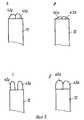
Внутриматочный контрацептив, имеющийся на рынке и освобождающий левоноргестрел, состоит из Т-образного ВМК, имеющего удлиненный элемент, изготовленный из полиэтилена, снабженного резервуаром, приспособленным вокруг него и содержащим гормон левоноргестрел. Контрацептив продается в стерильной упаковке вместе с устройством для ведения с плунжером, который представляет собой единую деталь, содержащуюся внутри защитной трубки. Т-образный контрацептив помещается на переднем конце плунжера с содержащим гормон удлиненным элементом, защищенным трубкой. Крылья поперечного элемента, с другой стороны, выступают для предотвращения усталости. Пружины, с помощью которых Т-образный контрацептив оттягивается по направлению наружу, проходят между плунжером и защитной трубкой и заканчиваются на конце ручки. На фиг. 1 показано одно такое устройство. Т-образные ВМК, имеющие удлиненный элемент, обмотанный медной проволокой, упакованы аналогичным образом. The intrauterine contraceptive available on the market and releasing levonorgestrel consists of a T-shaped IUD having an elongated element made of polyethylene equipped with a reservoir adapted around it and containing the hormone levonorgestrel. The contraceptive is sold in a sterile package along with a plunger guidance device, which is a single piece contained within the protective tube. A T-shaped contraceptive is placed on the front end of the plunger with a hormone-containing elongated element protected by a tube. The wings of the transverse element, on the other hand, protrude to prevent fatigue. The springs with which the T-shaped contraceptive is pulled outward pass between the plunger and the protective tube and end at the end of the handle. In FIG. 1 shows one such device. T-shaped IUDs having an elongated element wrapped in copper wire are similarly packaged.
Проблема, связанная с устройством для введения Т-образных контрацептивов, содержащих активные соединения, относится к достижению правильного расположения ВМК внутри защитной трубки. Сложность возникает вследствие большего диаметра удлиненного элемента этих устройств по сравнению с ВМК, содержащими медную проволоку, что означает, что диаметр защитной трубки также больше. Полусферические концевые детали крыльев поперечного элемента малы по отношению к диаметру защитной трубки. Поэтому крайне важно, чтобы эти концевые детали были в строго правильном положении по отношению к краю защитной трубки в момент введения устройства в матку. На фиг. 2A показан пример правильного расположения Т-образного устройства в защитной трубке устройства для введения. Если ВМК втягивается в защитную трубку посредством пружины удаления, что происходит с устройством, описанным выше, понятно, что трудно заставить ВМК остановиться в правильном положении, если относительное движение защитной трубки и плунжера не ограничено любым стопорным элементом. Втягивание с приложением слишком большой силы легко заставляет окончания крыльев поперечного элемента почти полностью входить в защитную трубку (фиг. 2B). Во время введения устройства острые края защитной трубки могут мешать введению устройства через шеечный канал. Если, с другой стороны, устройство недостаточно глубоко вводится в защитную трубку, возникает ситуация, подобная показанной на фиг. 2C, при которой крылья поперечного элемента выступают наружу ввиду слишком широкой защитной трубки. Диаметр на уровне крыльев остается слишком широким, что делает расположение устройства во время введения более трудным. Легче заставить крылья остановиться в правильном положении (фиг. 2D) в случае устройств с медной проволокой, потому что трубка узкая по отношению к крыльям. Поэтому нет опасности слишком глубокого вставления крыльев в трубку даже при втягивании с большим усилием. The problem associated with the device for the introduction of T-shaped contraceptives containing active compounds, relates to achieving the correct location of the IUD inside the protective tube. The difficulty arises due to the larger diameter of the elongated element of these devices compared to IUDs containing copper wire, which means that the diameter of the protective tube is also larger. The hemispherical end parts of the wings of the transverse element are small with respect to the diameter of the protective tube. Therefore, it is imperative that these end parts are in a strictly correct position with respect to the edge of the protective tube when the device is inserted into the uterus. In FIG. 2A shows an example of the correct placement of the T-shaped device in the protective tube of the insertion device. If the IUD is pulled into the protective tube by means of a removal spring, which happens with the device described above, it is clear that it is difficult to make the IUD stop in the correct position if the relative movement of the protective tube and plunger is not limited by any locking element. Retracting with too much force easily causes the wing ends of the transverse member to almost completely enter the protective tube (Fig. 2B). During insertion of the device, the sharp edges of the protective tube may interfere with the insertion of the device through the cervical canal. If, on the other hand, the device is not inserted deep enough into the protective tube, a situation similar to that shown in FIG. 2C, in which the wings of the transverse member protrude outward due to a too wide protective tube. The diameter at the wing level remains too wide, which makes the arrangement of the device during insertion more difficult. It is easier to make the wings stop in the correct position (Fig. 2D) in the case of devices with copper wire, because the tube is narrow in relation to the wings. Therefore, there is no danger of the wings being inserted too deep into the tube even when pulled in with great effort.
Известны способы в патентной литературе, в соответствии с которым ВМК помещается внутри защитной трубки, когда устройство вводится в матку. В патенте GP 1600717 описано устройство для введения, пригодное для Т-образных или Y-образных ВМК. ВМК оттягивается назад в защитную трубку с помощью прикрепленной пружины. Патентные публикации US 3842826 и WO 94/13233 также описывают способы ретракции ВМК в защитную трубку перед введением ВМК. В патенте GB 1403393 описан способ, при котором ВМК, содержащийся в защитной трубке, проталкивается по направлению к концу трубки перед введением устройства. Known methods in the patent literature, according to which the IUD is placed inside the protective tube when the device is inserted into the uterus. GP 1600717 describes an administration device suitable for T-shaped or Y-shaped IUDs. The VMK is pulled back into the protective tube using an attached spring. Patent publications US 3842826 and WO 94/13233 also describe methods of retraction of the IUD into the protective tube before the introduction of the IUD. GB 1403393 describes a method in which an IUD contained in a protective tube is pushed towards the end of the tube before introducing the device.
Ранее не были описаны способы, при которых ВМК вводится в защитную трубку путем натягивания трубки на устройство или путем вталкивания устройства в защитную трубку, где относительное движение плунжера и защитной трубки ограничено стопорным элементом для выяснения, что достигнута правильная конфигурация ВМК. Previously, methods have not been described in which the IUD is inserted into the protective tube by pulling the tube onto the device or by pushing the device into the protective tube, where the relative movement of the plunger and the protective tube is limited by the locking element to determine that the correct configuration of the IUD has been achieved.
Задачей настоящего изобретения является внедрение средства для решения проблем, описанных выше, и создание нового вида устройства для введения, которое позволяет правильно расположить ВМК также в тех случаях, при которых удлиненный элемент Т-образного ВМК содержит активный материал, что связано с диаметром большим, чем диаметр удлиненного элемента ВМК с медной проволокой. Задачей также является изготовление устройства для введения, которое является прочным и устойчивым и при котором нет опасности неупругого изгиба защитной трубки. The present invention is the introduction of a means to solve the problems described above, and the creation of a new type of device for the introduction, which allows you to correctly position the IUD also in those cases in which the elongated element of the T-shaped IUD contains the active material, which is associated with a diameter larger than the diameter of the elongated element VMK with copper wire. Another objective is the manufacture of an insertion device that is strong and stable and in which there is no danger of inelastic bending of the protective tube.
Характерные признаки изобретения раскрыты в пункте 1. The characteristic features of the invention are disclosed in paragraph 1.
Теперь изобретение будет описано со ссылками на следующие чертежи, на которых:
фиг. 1A - 1B иллюстрируют в качестве уровня технического решения единое сочетание устройства для введения и ВМК,
фиг. 2A - 2D иллюстрируют Т-образные ВМК, втянутые в защитную трубку правильным и неправильным образом,
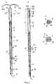
фиг. 3A - 3D иллюстрируют принцип работы устройства для введения в соответствии с изобретением,
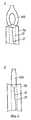
фиг. 4A - 4B иллюстрируют форму конца плунжера,
фиг. 5 иллюстрирует вариант реализации изобретения.The invention will now be described with reference to the following drawings, in which:
FIG. 1A to 1B illustrate, as a technical solution level, a single combination of an introduction device and an IUD,
FIG. 2A to 2D illustrate T-shaped IUDs drawn into the protective tube in a correct and incorrect manner,
FIG. 3A - 3D illustrate the principle of operation of the introduction device in accordance with the invention,
FIG. 4A to 4B illustrate the shape of the end of a plunger,
FIG. 5 illustrates an embodiment of the invention.
На фиг. 1A показана конструкция в соответствии с техническим уровнем, при котором Т-образный удлиненный элемент 45 ВМК 40 был помещен в защитную трубку 12 устройства для введения, и крылья 42 и 43 поперечного элемента ВМК расправлены. Плунжер 11 представляет собой твердый стержень с ручкой 20 на одном конце. Пружина(ы) для удаления 41 проходит(ят) в пространстве между плунжером 11 и защитной трубкой 12. Позиция 50 относится к сигнализирующему приспособлению, которое может скользить вдоль поверхности защитной трубки и размещаться в желаемом положении. Когда ВМК вставляется, сигнализирующее приспособление входит в контакт с шеечным каналом и сигнализирует о правильной глубине расположения ВМК. Перед приведением устройства в рабочее состояние пружина для удаления натягивается в направлении ручки 20. Это позволяет ввести ВМК в защитную трубку 12, в момент чего крылья 42 и 43 сложены друг с другом. На фиг. 1B показан ВМК, защищенный трубкой 12, в форме, в которой он вставлен. После того как конструкция, показанная на фиг. 1B, была помещена в матке так, что ВМК придано правильное положение, ВМК освобождается оттягиванием защитной трубки 12 по направлению наружу при удерживании на месте плунжера 11. In FIG. 1A shows a construction in accordance with the technical level in which a T-shaped
На фиг. 3A и 3B показан вариант реализации изобретения, который иллюстрирует принцип работы. На фиг. 3A показано устройство для введения 10 с ВМК 40, помещенным в переднем конце (вход в матку) так, что удлиненный элемент 45 располагается внутри защитной трубки 12. Перед введением пружина 41 сжимается и фиксируется в фиксирующем приспособлении (не показано на фигуре), связанном с плунжером 11, с кончиком удлиненного элемента, упирающимся в торцевой конец плунжера. Способ, показанный на этой фигуре, включает использование полого плунжера, и пружина 41 проходит преимущественно в канале 13 плунжера. Таким образом, пружина скользит свободно и нет опасности ее попадания в зажим между плунжером и трубкой. Плунжер имеет два прикрепленных радиально выступающих стопорных элемента R2 и R4. Чехол защитной трубки 12 имеет направленную по оси щель 14, соответствующую стопорным элементам R2 и R4 (поперечное сечение показано на фиг. 3C) и сконструированную для обеспечения возможности движения защитной трубки 12 в осевом направлении. Чехол защитной трубки имеет прикрепленный стопорный элемент R со стопорными поверхностями R1 и R3, выступающими в направлении радиуса плунжера. Фиг. 3D представляет собой поперечное сечение, показывающее стопорный элемент R. При подготовке к использованию устройства проверяется сжатие и фиксация пружины для удаления. Затем при удерживании ручки плунжера защитная трубка проталкивается по направлению к ВМК до тех пор, пока поверхность R1 стопорного элемента R не упрется в стопорный элемент R2, прекращая таким образом движение защитной трубки. В этот момент ВМК по существу находится внутри защитной трубки и готов к введению (фиг. 3B). Расположение стопорных элементов R1 и R2 было спроектировано так, чтобы обеспечить возможность проталкивания защитной трубки мимо плунжера на желаемое расстояние L, что в целом соответствует длине ВМК, собранного для введения. Стопорные элементы R1 и R2 преимущественно расположены так, что край 12a защитной трубки, который идет в матку, стопорится на уровне, на котором полусферические окончания 42a, 43a крыльев 42, 43 поперечного элемента Т-образного ВМК частично остаются непокрытыми защитной трубкой 12, тогда как крылья 42, 43 еще остаются вместе. In FIG. 3A and 3B show an embodiment of the invention that illustrates the principle of operation. In FIG. 3A shows a device for introducing 10 with a
Альтернативно поверхность R1 стопорного элемента R может удерживаться в контакте со стопорным элементом R2, в котором защитная трубка выступает за плунжер на расстояние, которое по существу соответствует длине ВМК, собранного для введения в матку. Если ВМК расположен в устройстве так, что удлиненный элемент 45 расположен внутри защитной трубки, но крылья 42, 43 находятся снаружи защитной трубки, ВМК может помещаться в правильное положение для введения путем вталкивания ВМК в защитную трубку. Alternatively, the surface R1 of the locking element R can be held in contact with the locking element R2, in which the protective tube extends beyond the plunger to a distance that substantially corresponds to the length of the IUD assembled for insertion into the uterus. If the IUD is located in the device so that the
Устройство, показанное на фиг. 3B, вталкивается в матку до тех пор, пока ВМК не займет правильное положение. ВМК освобождается из защитной трубки при удерживании плунжера в совершенно неподвижном положении путем отведения назад защитной трубки по направлению к ручке до тех пор, пока стопорная поверхность R3 не упрется в стопорный элемент R4, прикрепленный к плунжеру. Расположение стопорных приспособлений R3 и R4 было выбрано так, что при встрече этих стопорных приспособлений они ясно указывают момент, в который ВМК в переднем конце плунжера был освобожден от защитной трубки по мере его движения к ручке. Стопорный элемент R4 необязательно может быть сконструирован так, чтобы прекращать движение защитной трубки по направлению к ручке. The device shown in FIG. 3B, is pushed into the uterus until the IUD is in the correct position. The VMC is released from the protective tube while holding the plunger in a completely stationary position by pulling back the protective tube towards the handle until the locking surface R3 abuts against the locking element R4 attached to the plunger. The arrangement of the locking devices R3 and R4 was chosen so that when these locking devices meet, they clearly indicate the moment at which the IUD at the front end of the plunger was released from the protective tube as it moved to the handle. The locking element R4 may optionally be designed to stop the movement of the protective tube towards the handle.
Стопорные элементы R2 и R4 необязательно должны быть прикреплены к самому плунжеру, как показано на фиг. 3A - 3D. Вместо этого они могут образовывать часть элемента, который сам подсоединен к плунжеру. То же относится к стопорным элементам R1 и R3: они могут быть прикреплены к самой защитной трубке или к элементу, соединенному с защитной трубкой. Стопорные элементы R1 и R3 могут образовывать часть того же элемента R, как на фиг. 3A - 3B, но они могут также быть отдельными элементами. The locking elements R2 and R4 need not be attached to the plunger itself, as shown in FIG. 3A - 3D. Instead, they can form part of an element that is itself connected to the plunger. The same applies to the locking elements R1 and R3: they can be attached to the protective tube itself or to the element connected to the protective tube. The locking elements R1 and R3 may form part of the same element R as in FIG. 3A to 3B, but they can also be separate elements.
Плунжер является преимущественно полым или имеет борозду, идущую в осевом направлении и позволяющую пружине 41 свободно скользить в ней. The plunger is predominantly hollow or has a furrow extending in the axial direction and allowing the
Важно при вставлении Т-образного ВМК, чтобы крылья могли выступать в стороны, а не вперед или назад (как расценивается пациентом). Направленная жесткость ВМК во время введения может обеспечиваться, например, приданием такой формы переднему концу плунжера, что ВМК приобретает особую постоянную конфигурацию при оттягивании пружины. Таким образом, ВМК не будет поворачиваться во время введения. Пример такой конструкции представлен на фиг. 4A и 4B. Конец 45b удлиненного элемента, упирающийся в плунжер, имеет форму проушины, которая имеет прикрепленную пружину 41 для оттягивания. На фигурах показано, что передний конец 11a плунжера находится не на уровне, а утоплен для образования углубления типа воронкообразной впадины. Когда пружина 41, прикрепленная к проушине 45b, оттягивается, проушина 45b скользит в воронкообразную впадину и захватывается в ней. Фиг. 4A представляет собой фронтальную проекцию, а фиг. 4B является видом сбоку проушины 45. It is important when inserting a T-shaped IUD so that the wings can protrude to the sides and not forward or backward (as the patient regards). The directional rigidity of the BMC during insertion can be provided, for example, by shaping the front end of the plunger so that the BMC acquires a special permanent configuration when the spring is pulled. Thus, the IUD will not rotate during administration. An example of such a construction is shown in FIG. 4A and 4B. The end 45b of the elongated member abutting against the plunger has an eye shape that has an attached
Передние части (направленные к матке) плунжера и защитной трубки могут быть прямыми или изогнутыми так, чтобы соответствовать анатомии матки. The front parts (directed towards the uterus) of the plunger and protective tube can be straight or curved so as to match the anatomy of the uterus.
Подходящий вариант реализации изобретения показан на фиг. 5. Передняя часть 20' ручки 20 образует конструкцию 21, идущую в продольном направлении плунжера. Конструкция имеет в переднем конце 21' канал, в котором защитная трубка 12 будет скользить в продольном направлении. Защитная трубка имеет кнопку R на дистальном конце (противоположном от матки). Поверхность R1 по направлению к матке, кнопки R и поверхность 21a по направлению к ручке 20 конца 21' конструкции 21 вместе образуют пару стопорных элементов R1, R2. Край R3 по направлению от матки, кнопки R и поверхность 21b основания конструкции 21 вместе образуют пару стопорных элементов R3, R4. A suitable embodiment of the invention is shown in FIG. 5. The front portion 20 'of the
По желанию, одно или более сигнальных приспособлений могут устанавливаться между стопорными элементами R1/R2 и R3/R4. Такое сигнальное приспособление может, например, быть расположено таким образом, что врач при подготовке к освобождению ВМК отметит момент, в который крылья поперечного элемента ВМК были освобождены из защитной трубки, в то время как удлиненный элемент еще защищен трубкой. Такое сигнальное приспособление, естественно, не должно активно препятствовать ретракции трубки, потому что в этом случае ВМК нельзя будет освободить. Optionally, one or more signaling devices can be installed between the locking elements R1 / R2 and R3 / R4. Such a signaling device can, for example, be positioned in such a way that the doctor, in preparation for the release of the IUD, will note the moment at which the wings of the transverse element of the IUD were released from the protective tube, while the elongated element is still protected by the tube. Such a signal device, of course, should not actively interfere with the retraction of the tube, because in this case the IUD cannot be released.
Это изобретение предоставляет устройство для введения, которое позволяет легко расположить ВМК в предварительно определенное положение в защитной трубке, потому что стопорные элементы гарантируют точное расположение ВМК во время введения и его точное освобождение. В соответствии с этим изобретением нет необходимости создавать столь большой зазор между плунжером и защитной трубкой, как в устройствах для введения, в которых ВМК располагаются путем ретракции без любого стопорного элемента, который прекращает движение ВМК. Это приводит к исключительно устойчивой конструкции, которая не связана с опасностью неустранимого изгиба трубки. This invention provides an insertion device that makes it easy to position the IUD in a predetermined position in the protective tube, because the locking elements guarantee the exact location of the IUD during insertion and its precise release. In accordance with this invention, there is no need to create such a large gap between the plunger and the protective tube, as in the devices for the introduction, in which the IUDs are located by retraction without any locking element that stops the movement of the IUD. This leads to an exceptionally stable construction that is not associated with the danger of irreparable bending of the tube.
Устройство для введения в соответствии с изобретением особенно пригодно для расположения Т-образных ВМК, но оно также применимо к другим типам ВМК в той мере, в какой они могут быть введены в защитную трубку с помощью соответствующих приспособлений. The insertion device in accordance with the invention is particularly suitable for locating T-shaped IUDs, but it is also applicable to other types of IUDs to the extent that they can be inserted into the protective tube using appropriate devices.
Хотя изобретение применимо для расположения ВМК медно-проволочного типа, его преимущества будут лучше понятны в случае устройств, содержащих активные агенты. Устройство для введения в соответствии с этим изобретением особенно пригодно для расположения таких Т-образных ВМК, которые имеют удлиненный элемент 45, имеющий подобный кожуху полимерный резервуар, содержащий активный агент, намотанный вокруг него. Although the invention is applicable to the location of the IWC copper-wire type, its advantages will be better understood in the case of devices containing active agents. An introduction device in accordance with this invention is particularly suitable for locating such T-shaped IUDs that have an elongated
Подходящие активные агенты включают гормоны, используемые для лечения постклимактерических расстройств или для контрацепции. Suitable active agents include hormones used to treat postmenopausal disorders or for contraception.
Специалисты в этой области поймут, что много различных вариантов и модификаций настоящего изобретения попадают в диапазон пунктов формулы изобретения, представленных в следующем разделе. Those skilled in the art will recognize that many different variations and modifications of the present invention fall within the scope of the claims presented in the next section.
Claims (9)
Translated fromRussianApplications Claiming Priority (3)
| Application Number | Priority Date | Filing Date | Title |
|---|---|---|---|
| FI945895 | 1994-12-15 | ||
| FI945895AFI97946C (en) | 1994-12-15 | 1994-12-15 | Depositor intended for setting up a device for intrauterine use |
| PCT/FI1995/000666WO1996018365A1 (en) | 1994-12-15 | 1995-12-05 | Inserter for the positioning of an intrauterine device |
Publications (1)
| Publication Number | Publication Date |
|---|---|
| RU2129416C1true RU2129416C1 (en) | 1999-04-27 |
Family
ID=8541983
Family Applications (1)
| Application Number | Title | Priority Date | Filing Date |
|---|---|---|---|
| RU97111313ARU2129416C1 (en) | 1994-12-15 | 1995-12-05 | Device for introduction of intrauterine contraceptive |
Country Status (28)
| Country | Link |
|---|---|
| US (1) | US5785053A (en) |
| EP (1) | EP0798999B1 (en) |
| JP (1) | JPH10510444A (en) |
| KR (1) | KR100393708B1 (en) |
| CN (1) | CN1147277C (en) |
| AT (1) | ATE235201T1 (en) |
| AU (1) | AU693297B2 (en) |
| BG (1) | BG62472B1 (en) |
| BR (1) | BR9510078A (en) |
| CA (1) | CA2204368C (en) |
| CZ (1) | CZ286820B6 (en) |
| DE (2) | DE69530112T9 (en) |
| DK (1) | DK0798999T3 (en) |
| ES (1) | ES2108664T3 (en) |
| FI (1) | FI97946C (en) |
| GR (1) | GR980300001T1 (en) |
| HU (1) | HU218760B (en) |
| IS (1) | IS1779B (en) |
| NO (1) | NO309406B1 (en) |
| NZ (1) | NZ296544A (en) |
| PL (1) | PL178474B1 (en) |
| PT (1) | PT798999E (en) |
| RO (1) | RO116862B1 (en) |
| RU (1) | RU2129416C1 (en) |
| SI (1) | SI9520150B (en) |
| SK (1) | SK282290B6 (en) |
| UA (1) | UA42812C2 (en) |
| WO (1) | WO1996018365A1 (en) |
Cited By (2)
| Publication number | Priority date | Publication date | Assignee | Title |
|---|---|---|---|---|
| US11090186B2 (en) | 2011-07-11 | 2021-08-17 | Medicines360 | Methods for using intrauterine systems and IUD insertion devices |
| RU2755384C2 (en)* | 2016-10-06 | 2021-09-15 | Байер Ою | Complex for intrauterine system and its installation tool |
Families Citing this family (34)
| Publication number | Priority date | Publication date | Assignee | Title |
|---|---|---|---|---|
| BR0005070B1 (en)* | 2000-09-06 | 2008-11-18 | process of obtaining intrauterine contraceptive device and resulting product. | |
| EP1639972B1 (en) | 2001-08-01 | 2013-09-11 | Anecova SA | Intrauterine device |
| FI119719B (en)* | 2003-11-19 | 2009-02-27 | Bayer Schering Pharma Oy | A slider |
| CN1294886C (en)* | 2005-03-02 | 2007-01-17 | 东南大学 | Device for taking out intrauterine device |
| US7862552B2 (en) | 2005-05-09 | 2011-01-04 | Boston Scientific Scimed, Inc. | Medical devices for treating urological and uterine conditions |
| EP2057972A1 (en)* | 2007-11-07 | 2009-05-13 | N.V. Organon | Intrauterine deposit |
| ES2424984T5 (en)* | 2008-09-17 | 2017-02-16 | Bayer Oy | Inserter |
| FI20080524A0 (en)* | 2008-09-17 | 2008-09-17 | Bayer Schering Pharma Oy | An inserter |
| FI20080523A0 (en)† | 2008-09-17 | 2008-09-17 | Bayer Schering Pharma Oy | An inserter |
| US11992431B2 (en) | 2008-09-17 | 2024-05-28 | Bayer Oy | Inserter |
| USD791318S1 (en) | 2009-09-14 | 2017-07-04 | Bayer Oy | Inserter |
| US8573222B2 (en) | 2010-03-21 | 2013-11-05 | David Weintraub | Intrauterine device and inserter for the same |
| CN103209663B (en)* | 2010-10-18 | 2016-08-10 | 碧奥塞普蒂夫股份有限公司 | For device or medicine are inserted endoceliac method and apparatus |
| FI122579B (en)* | 2010-10-29 | 2012-03-30 | Bayer Oy | inserter |
| JP6068350B2 (en) | 2010-10-29 | 2017-01-25 | オディセア・ファルマ・ソシエテ・プリベ・ア・レスポンサビリテ・リミテOdyssea Pharma S.P.R.L. | Intrauterine insertion device |
| AU2015221468B2 (en)* | 2011-07-11 | 2017-08-24 | Medicines360 | Intrauterine systems, IUD insertion devices, and related methods and kits therefor |
| USD718435S1 (en) | 2012-05-30 | 2014-11-25 | Medicines360 | Intrauterine insertion device |
| US9265652B2 (en) | 2012-08-14 | 2016-02-23 | Contramed, Llc | Intrauterine contraceptive device |
| US9089418B2 (en) | 2012-08-14 | 2015-07-28 | Contramed, Llc | Intrauterine contraceptive device |
| US10188546B2 (en) | 2013-10-14 | 2019-01-29 | Sebela Vlc Limited | Intrauterine device with controlled copper ion elution |
| US10918516B2 (en) | 2013-10-14 | 2021-02-16 | Sebela Vlc Limited | Intrauterine device with controlled copper ion elution |
| US9180040B2 (en) | 2013-10-18 | 2015-11-10 | Contramed, Llc | Intrauterine device with retrieval thread |
| CN104323829B (en)* | 2014-11-06 | 2017-09-22 | 复旦大学附属肿瘤医院 | Uterine neck pore prevents adhesion device and its application |
| US10206595B2 (en) | 2014-11-17 | 2019-02-19 | 3VO Medical, Inc. | Intrauterine balloon apparatus, system, and method for augmenting uterine birthing forces during parturition |
| WO2017013668A1 (en)* | 2015-07-21 | 2017-01-26 | Pregna International Limited | An apparatus for loading, insertion and placement of an intrauterine contraceptive device and process thereof |
| US11278445B2 (en)* | 2015-07-30 | 2022-03-22 | Medicines360 | IUD loading devices and methods for inserting an IUD into an insertion device |
| EP3331477A1 (en)* | 2015-08-07 | 2018-06-13 | PAT&Co bvba | Novel instrument for the insertion of a bioactive frameless or framed intrauterine device or intrauterine system through a hysteroscope |
| US11571328B2 (en) | 2018-04-09 | 2023-02-07 | Medicines360 | IUD insertion devices |
| US20200261258A1 (en) | 2019-02-19 | 2020-08-20 | Medicines360 | Devices, systems, methods and kits for insertion and removal of iuds |
| US11571329B2 (en) | 2019-11-21 | 2023-02-07 | Coopersurgical, Inc. | Packaging systems for implantable devices and related methods |
| US11963904B2 (en) | 2020-09-23 | 2024-04-23 | Pregna International Limited | Instrument to prepare and safely place an intra-uterine device |
| US11969377B2 (en) | 2021-10-27 | 2024-04-30 | Pregna International Limited | Single-use instrument to prepare and safely place an intra-uterine device |
| FR3138299B1 (en) | 2022-07-26 | 2025-04-18 | Patrick Choay Sas | Inserter for inserting an intrauterine device |
| WO2025110136A1 (en)* | 2023-11-21 | 2025-05-30 | 国立大学法人東京科学大学 | Embryo transfer device |
Citations (4)
| Publication number | Priority date | Publication date | Assignee | Title |
|---|---|---|---|---|
| US3842826A (en)* | 1972-10-25 | 1974-10-22 | Hollister Inc | Intrauterine contraceptive device and inserter therefor |
| GB1403393A (en)* | 1971-10-07 | 1975-08-28 | Robins Co Inc A H | Inserters for intrauterine devices |
| GB1543841A (en)* | 1975-07-16 | 1979-04-11 | Searle & Co | Instrument for positioning an intrauterine device |
| WO1994013233A1 (en)* | 1992-12-04 | 1994-06-23 | Schering Aktiengesellschaft | Combination of a contraceptive device for the uterus and a suitable applicator |
Family Cites Families (10)
| Publication number | Priority date | Publication date | Assignee | Title |
|---|---|---|---|---|
| US3678927A (en)* | 1968-03-18 | 1972-07-25 | Samuel Soichet | Intra uterine device and injector thereof |
| NL6915483A (en)* | 1969-10-14 | 1971-04-16 | ||
| US3678947A (en)* | 1970-07-16 | 1972-07-25 | Melvin J Davidson | Eyeliner |
| US4026281A (en)* | 1973-10-12 | 1977-05-31 | Ortho Pharmaceutical Corporation | Method and apparatus for inserting an intrauterine contraceptive device |
| NL7802043A (en)* | 1977-03-28 | 1978-10-02 | Ortho Pharma Corp | INSTRUMENT FOR THE INSERTION OF AN INTRA-UTERINE ANTI-CONCEPTION AGENT AND A METHOD FOR THE INSERTION OF AN INTRA-UTERINE ANTI-CONCEPTION AGENT. |
| ES239677Y (en)* | 1978-11-23 | 1979-06-16 | Sopena Quesada Angel | INTRAUTERINE SPERM |
| EP0049660A1 (en)* | 1980-10-03 | 1982-04-14 | Laboratoires Cilag-Chimie S.A.R.L. | Instrument for inserting an intra-uterine device, and assembly thereof |
| IN161985B (en)* | 1984-03-29 | 1988-03-12 | Wildemeersch Dirk | |
| DE9201809U1 (en)* | 1992-02-13 | 1992-10-01 | Augustin, Rainer, 7801 Bremgarten | Insertion device for intrauterine devices |
| DE4318941C2 (en)* | 1993-05-27 | 1995-04-27 | Schering Ag | Combination of an intra-uterine contraceptive device and an introducer |
- 1994
- 1994-12-15FIFI945895Apatent/FI97946C/ennot_activeIP Right Cessation
- 1995
- 1995-12-05UAUA97063400Apatent/UA42812C2/enunknown
- 1995-12-05HUHU9701808Apatent/HU218760B/enunknown
- 1995-12-05ATAT95939298Tpatent/ATE235201T1/enactive
- 1995-12-05SISI9520150Apatent/SI9520150B/enunknown
- 1995-12-05DEDE69530112Tpatent/DE69530112T9/enactiveActive
- 1995-12-05EPEP95939298Apatent/EP0798999B1/ennot_activeExpired - Lifetime
- 1995-12-05CZCZ19971701Apatent/CZ286820B6/ennot_activeIP Right Cessation
- 1995-12-05SKSK723-97Apatent/SK282290B6/ennot_activeIP Right Cessation
- 1995-12-05PLPL95320332Apatent/PL178474B1/enunknown
- 1995-12-05RURU97111313Apatent/RU2129416C1/enactive
- 1995-12-05RORO97-01020Apatent/RO116862B1/enunknown
- 1995-12-05CACA002204368Apatent/CA2204368C/ennot_activeExpired - Lifetime
- 1995-12-05ESES95939298Tpatent/ES2108664T3/ennot_activeExpired - Lifetime
- 1995-12-05PTPT95939298Tpatent/PT798999E/enunknown
- 1995-12-05KRKR1019970703005Apatent/KR100393708B1/ennot_activeExpired - Lifetime
- 1995-12-05USUS08/849,550patent/US5785053A/ennot_activeExpired - Lifetime
- 1995-12-05CNCNB951966553Apatent/CN1147277C/ennot_activeExpired - Lifetime
- 1995-12-05BRBR9510078Apatent/BR9510078A/ennot_activeIP Right Cessation
- 1995-12-05WOPCT/FI1995/000666patent/WO1996018365A1/enactiveIP Right Grant
- 1995-12-05NZNZ296544Apatent/NZ296544A/ennot_activeIP Right Cessation
- 1995-12-05DKDK95939298Tpatent/DK0798999T3/enactive
- 1995-12-05DEDE0798999Tpatent/DE798999T1/enactivePending
- 1995-12-05JPJP8518303Apatent/JPH10510444A/enactivePending
- 1995-12-05AUAU41180/96Apatent/AU693297B2/ennot_activeExpired
- 1997
- 1997-06-06NONO972604Apatent/NO309406B1/ennot_activeIP Right Cessation
- 1997-06-13ISIS4506Apatent/IS1779B/enunknown
- 1997-07-04BGBG101744Apatent/BG62472B1/enunknown
- 1998
- 1998-02-27GRGR980300001Tpatent/GR980300001T1/enunknown
Patent Citations (4)
| Publication number | Priority date | Publication date | Assignee | Title |
|---|---|---|---|---|
| GB1403393A (en)* | 1971-10-07 | 1975-08-28 | Robins Co Inc A H | Inserters for intrauterine devices |
| US3842826A (en)* | 1972-10-25 | 1974-10-22 | Hollister Inc | Intrauterine contraceptive device and inserter therefor |
| GB1543841A (en)* | 1975-07-16 | 1979-04-11 | Searle & Co | Instrument for positioning an intrauterine device |
| WO1994013233A1 (en)* | 1992-12-04 | 1994-06-23 | Schering Aktiengesellschaft | Combination of a contraceptive device for the uterus and a suitable applicator |
Cited By (3)
| Publication number | Priority date | Publication date | Assignee | Title |
|---|---|---|---|---|
| US11090186B2 (en) | 2011-07-11 | 2021-08-17 | Medicines360 | Methods for using intrauterine systems and IUD insertion devices |
| US12004992B2 (en) | 2011-07-11 | 2024-06-11 | Medicines360 | Kits for intrauterine systems and IUD insertion devices |
| RU2755384C2 (en)* | 2016-10-06 | 2021-09-15 | Байер Ою | Complex for intrauterine system and its installation tool |
Also Published As
Similar Documents
| Publication | Publication Date | Title |
|---|---|---|
| RU2129416C1 (en) | Device for introduction of intrauterine contraceptive | |
| US11911312B2 (en) | Inserter | |
| US20240173163A1 (en) | Inserter | |
| KR101604508B1 (en) | An inserter | |
| US10149784B2 (en) | Inserter for an intrauterine system | |
| US12201553B2 (en) | Inserter for an intrauterine system | |
| MXPA97003985A (en) | Insertion element for the placement of an intrauter device | |
| HK1005222B (en) | Inserter for the positioning of an intrauterine device | |
| HK1155351B (en) | An inserter | |
| HK1155349B (en) | An inserter |