RU2125844C1 - Guide for formation of canals for transplants of knee joint cruciate ligaments - Google Patents
Guide for formation of canals for transplants of knee joint cruciate ligamentsDownload PDFInfo
- Publication number
- RU2125844C1 RU2125844C1RU98110212ARU98110212ARU2125844C1RU 2125844 C1RU2125844 C1RU 2125844C1RU 98110212 ARU98110212 ARU 98110212ARU 98110212 ARU98110212 ARU 98110212ARU 2125844 C1RU2125844 C1RU 2125844C1
- Authority
- RU
- Russia
- Prior art keywords
- rod
- guide
- bracket
- tie
- clamp
- Prior art date
Links
Images


Landscapes
- Surgical Instruments (AREA)
Abstract
Description
Translated fromRussianИзобретение может быть использовано для открытой и артроскопической хирургии при восстановлении поврежденных крестообразных связок коленного сустава. The invention can be used for open and arthroscopic surgery when restoring damaged cruciate ligaments of the knee joint.
Известен направитель для формирования каналов в большеберцовой кости при восстановлении поврежденной передней крестообразной связки коленного сустава (см. патент США 5350383, кл. А 61 F 5/04, 1994) [1]. Known guide for the formation of channels in the tibia during the restoration of the damaged anterior cruciate ligament of the knee joint (see US patent 5350383, CL A 61 F 5/04, 1994) [1].
За прототип выбран направитель, описанный в патенте США 5562664, кл. А 61 F 5/04, 1996 [2], который, как и [1], предназначен для формирования каналов в большеберцовой кости. For the prototype of the selected guide, described in US patent 5562664, cl. A 61 F 5/04, 1996 [2], which, like [1], is designed to form channels in the tibia.
В патенте [1] , как и в [2], направитель содержит направляющую скобу с угловой шкалой и направляющим пазом, на которой подвижно размещена сменная штанга. На рабочем конце штанги выполнен крюк, предназначенный для углубления и фиксации, а на опорном конце штанги установлена манжета. Шток под спицу снабжен мерной шкалой и консольно скреплен с направляющей скобой с возможностью осевого перемещения. Положением спицы управляет кнопочный переключатель. In the patent [1], as in [2], the guide comprises a guide bracket with an angular scale and a guide groove on which the replaceable rod is movably placed. A hook is made at the working end of the rod for deepening and fixing, and a cuff is installed at the supporting end of the rod. The rod for the spoke is equipped with a measuring scale and is cantilevered with a guide bracket with the possibility of axial movement. The position of the spokes is controlled by a push button switch.
Средство для крепления штанги как в [1], так и в [2], выполнено в виде сдвоенного клавишного переключателя, который образован двумя подпружиненными кулачками, шарнирно скрепленными с основанием средства для перемещения штанги. Подпружиненные кулачки охватывают и удерживают манжету опорного конца штанги. При замене штанги нужно нажать на сдвоенный клавишный переключатель и кулачки, преодолевая усилие пружины, освободят манжету и штангу можно заменить. The means for attaching the rod in both [1] and [2] are made in the form of a dual key switch, which is formed by two spring-loaded cams pivotally attached to the base of the means for moving the rod. Spring-loaded cams grasp and hold the cuff of the support end of the rod. When replacing the rod, you need to press the dual key switch and the cams, overcoming the force of the spring, release the cuff and the rod can be replaced.
В направителе [2] предусмотрено приспособление со щелью, которое устанавливается на штанге на место крюка, что позволяет хирургу с помощью артроскопа наблюдать положение спицы при сверлении канала в большеберцовой кости. In the guide [2], a device with a slit is provided, which is mounted on the bar in place of the hook, which allows the surgeon to use the arthroscope to observe the position of the spokes when drilling the canal in the tibia.
Средство для перемещения штанги как в [2], так и в [1], образовано охватывающим направляющую скобу основанием, в котором выполнено смотровое окно. Внутри основания размещен подпружиненный сухарь, через который основание связано с направляющим пазом скобы, а пружина сухаря взаимодействует с кнопочным выключателем, который управляет перемещением штанги. The means for moving the rod both in [2] and in [1] is formed by a base covering the guide bracket, in which the viewing window is made. A spring-loaded cracker is placed inside the base, through which the base is connected to the guide groove of the bracket, and the cracker spring interacts with a push button switch that controls the movement of the rod.
Однако недостаточная жесткость крепления кулачков сдвоенного клавишного переключателя приводит к нежелательному перемещению и уводу крюка штанги, что ведет к снижению точности. However, insufficient rigidity of the cams of the dual key switch leads to undesirable movement and withdrawal of the rod hook, which leads to a decrease in accuracy.
Дополнительно к этому при сверлении спицей направляющего канала пересечение крюка и спицы происходит в кости, и точку их пересечения невозможно зафиксировать с достаточной точностью. Пониженная точность формирования каналов и их входных точек может привести к "гильотинному" эффекту, к импинджмент-синдрому, к повторным микротравмам с образованием "циклоп"-синдромов, что осложняет восстановление функций коленного сустава и может привести к повторной нестабильности сустава. In addition, when drilling the needle of the guide channel, the intersection of the hook and spoke occurs in the bone, and the point of their intersection cannot be fixed with sufficient accuracy. The reduced accuracy of the formation of channels and their entry points can lead to a “guillotine” effect, to impingement syndrome, to repeated microtraumas with the formation of “cyclops” syndromes, which complicates the restoration of functions of the knee joint and can lead to repeated instability of the joint.
Еще один недостаток состоит в ограниченных возможностях известных направителей из-за того, что направители не предусматривают формирование каналов под углом, отличным от угла, задаваемого крюком штанги. Another disadvantage is the limited capabilities of the known guides due to the fact that the guides do not provide for the formation of channels at an angle different from the angle specified by the hook of the rod.
Кроме того, направитель ограничен в возможностях, поскольку пригоден только для формирования каналов в большеберцовой кости. In addition, the guide is limited in possibilities, since it is suitable only for the formation of channels in the tibia.
Технический результат предложенного технического решения состоит в расширении возможностей направителя за счет сверления каналов на любом рабочем угле как в большеберцовой, так и в бедренной кости при одновременном повышении точности формирования каналов и их входных точек, в снижении травматичности и в увеличении удобств в эксплуатации. The technical result of the proposed technical solution consists in expanding the capabilities of the guide by drilling channels on any working angle both in the tibia and in the femur while improving the accuracy of channel formation and their entry points, reducing trauma and increasing ease of use.
В предложенном направителе для формирования каналов под трансплантаты крестообразных связок коленного сустава, содержащем направляющую скобу с угловой шкалой и с направляющим пазом, шток под спицу с мерной шкалой, консольно скрепленный с направляющей скобой с возможностью осевого перемещения, кнопочный переключатель положения спицы, сменную штангу для формирования каналов в большеберцовой кости, на рабочем конце которой установлено средство для углубления и фиксации, а на опорном конце - манжета, средство для крепления штанги и средство для перемещения штанги вдоль скобы, которое образовано основанием со смотровым окном и подпружиненным сухарем, размещенным внутри основания и взаимосвязывающим основание с направляющим пазом скобы, который образует с сухарем направляющее гнездо, и кнопочным выключателем, взаимодействующим с пружиной сухаря для перемещения штанги вдоль скобы, это достигается тем, что средство для углубления и фиксации штанги выполнено в виде кольцевого упора с пилообразными насечками на рабочем торце и с направляющим отверстием, переходящим в паз овальной формы для образования со спицей шарнира, при этом направитель снабжен удлинителем скобы с угловой шкалой и дополнительной штангой для проведения каналов в бедренной кости, которая выполнена в виде жестко связанных под углом опорного конца и рабочего конца, скрепленного с кольцевым упором, центр которого и геометрические центры направляющей скобы и удлинителя скобы совмещены в одной точке, опорный конец дополнительной штанги скреплен с удлинителем скобы, а угол, смежный углу, образованному опорным и рабочим концами дополнительной штанги равен порядка 25-30o, причем направляющий паз скобы выполнен сквозным со стороны крепления штанги и снабжен скрепленным с ним ограничителем углов, удлинитель скобы связан со сквозным направляющим пазом и установлен в направляющем гнезде средства для перемещения штанги вдоль скобы с возможностью перемещения и взаимодействия с ограничителем углов, а средство для крепления сменной штанги образовано соединением винт-гайка, винт которого жестко связан с основанием и выполнен с отверстием, в котором установлена шпилька, а гайка соосно охватывает опирающуюся на винт манжету опорного конца штанги, который выполнен с сегментным срезом и размещен в отверстии винта с возможностью взаимодействия сегментного среза со шпилькой.In the proposed guide for forming channels for transplants of the cruciate ligaments of the knee joint, containing a guiding bracket with an angular scale and with a guiding groove, a rod for a spoke with a measuring scale, cantilevered with a guiding bracket with the possibility of axial movement, a push-button switch of the position of the knitting needle, an interchangeable rod for forming channels in the tibia, on the working end of which is installed a tool for deepening and fixing, and on the supporting end is a cuff, a tool for attaching the rod and medium in to move the rod along the bracket, which is formed by the base with a viewing window and a spring loaded cracker located inside the base and interconnecting the base with the guide groove of the bracket, which forms a guide slot with the cracker, and a push-button switch that interacts with the cracker spring to move the rod along the bracket, this is achieved by the fact that the means for deepening and fixing the rod is made in the form of an annular stop with sawtooth notches on the working end and with a guide hole turning into a groove about the shaft shape for education with a hinge needle, while the guide is equipped with an extension bracket with an angular scale and an additional rod for channeling in the femur, which is made in the form of a rigidly connected at an angle of the supporting end and the working end, fastened with an annular stop, the center of which is geometric the centers of the guide bracket and the bracket extension are aligned at one point, the supporting end of the additional rod is fastened to the bracket extension, and the angle adjacent to the angle formed by the supporting and working ends of the additional d is the rod of the order of 25-30o, wherein the guide groove is formed staples from the through rods and provided with a fastening secured to them angles limiter extension bracket is connected with the through guide groove and guide means mounted in the socket to move the rod along the bracket movably and interaction with an angle limiter, and the means for attaching the replaceable rod is formed by a screw-nut connection, the screw of which is rigidly connected to the base and is made with a hole in which the stud is installed, and the nut is aligned a cover supported on the screw rod end bearing collar which is formed with a segment cut and placed in the screw hole to engage with the pin cut segment.
Кроме того, это может быть достигнуто тем, что кольцевой упор штанги выполнен со сквозной щелью с боковой стороны для прохода спицы. In addition, this can be achieved by the fact that the annular stop of the rod is made with a through slot on the side for passing the spokes.
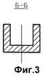
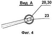
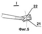
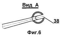
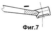
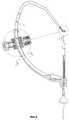
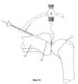
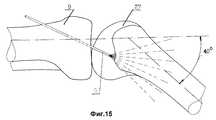
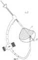
На фиг. 1 представлен внешний вид направителя для режима проведения канала в большеберцовой кости; на фиг. 2 - конструктивная схема направителя и дано сечение средства для крепления штанги и средства для перемещения штанги вдоль скобы; на фиг. 3 - сечение направляющей скобы Б-Б на фиг.2; на фиг. 4 - кольцевой упор (вид сверху); на фиг. 5 - кольцевой упор, разрез; на фиг. 6 - кольцевой упор со сквозной щелью (вид сверху); на фиг. 7 - кольцевой упор со сквозной щелью, разрез; на фиг. 8 - внешний вид направителя для проведения спицы в бедренной кости; на фиг.9 - конструктивная схема направителя с дополнительной штангой и дано сечение средства для перемещения скобы; на фиг. 10 - сечение направляющей скобы и удлинителя скобы Г-Г на фиг.9; на фиг. 11 - сечение средства для крепления штанги и средства для перемещения штанги вдоль скобы в режиме формирования канала в большеберцовой кости (в увеличенном масштабе); на фиг. 12 - сечение средства для крепления штанги и средства для перемещения штанги вдоль скобы и показано расположение в нем удлинителя скобы (в увеличенном масштабе); на фиг. 13 - схема расположения направителя относительно коленного сустава при определении направления канала в большеберцовой кости; на фиг. 14 - схема расположения направителя относительно коленного сустава после нахождения точки входа в канал бедренной кости; на фиг. 15 - схематично показано возможное расположение каналов под трансплантат в бедренной кости коленного сустава в сагиттальной плоскости; на фиг. 16 - возможное расположение каналов под трансплантат в бедренной кости коленного сустава во фронтальной плоскости; на фиг. 17 - схема проведения спицы в бедренной кости. In FIG. 1 shows the appearance of the guide for the mode of conducting the canal in the tibia; in FIG. 2 is a structural diagram of the guide and given a section of the means for attaching the rod and means for moving the rod along the bracket; in FIG. 3 is a cross section of a guide bracket BB in FIG. 2; in FIG. 4 - annular emphasis (top view); in FIG. 5 - annular emphasis, section; in FIG. 6 - annular emphasis with a through slot (top view); in FIG. 7 - an annular emphasis with a through slot, a section; in FIG. 8 - the appearance of the guide for holding the knitting needles in the femur; figure 9 is a structural diagram of a guide with an additional rod and given a section of the means for moving the bracket; in FIG. 10 is a cross section of a guide bracket and extension bracket GG in FIG. 9; in FIG. 11 is a cross-section of the means for attaching the rod and means for moving the rod along the bracket in the mode of channel formation in the tibia (on an enlarged scale); in FIG. 12 is a sectional view of the means for attaching the rod and means for moving the rod along the bracket and the location of the extension of the bracket (shown on an enlarged scale) is shown; in FIG. 13 is a diagram of the location of the guide relative to the knee joint when determining the direction of the canal in the tibia; in FIG. 14 is a diagram of the location of the guide relative to the knee joint after finding the entry point into the femoral canal; in FIG. 15 - schematically shows the possible location of the channels under the graft in the femur of the knee joint in the sagittal plane; in FIG. 16 - the possible location of the channels under the graft in the femur of the knee joint in the frontal plane; in FIG. 17 is a diagram of the needles in the femur.
Направитель для формирования каналов под трансплантат крестообразных связок коленного сустава содержит направляющую скобу 1 с угловой шкалой 2 и с направляющим пазом 3 (см. фиг.1 и 2), шток 4 под спицу 5 (51) с мерной шкалой 6, консольно скрепленный с направляющей скобой 1 с возможностью осевого перемещения, кнопочный переключатель 7 положения спицы 5 (51), сменную штангу 8 для формирования канала в большеберцовой кости 9, на рабочем конце которой установлено средство 10 для углубления и фиксации, а на опорном конце - манжета 11. Направитель содержит средство 12 для крепления штанги и средство 13 для перемещения штанги вдоль скобы (см. фиг.2, 11), которое образовано основанием 14 со смотровым окном 15 и подпружиненным сухарем 16, размещенным внутри основания 14 и взаимосвязывающим основанием 14 с направляющим пазом 3 скобы 1, с которым сухарь 16 образует направляющее гнездо 17 и кнопочным выключателем 18, взаимодействующим с пружиной 19 сухаря 16 для перемещения штанги 8 вдоль скобы 1.The guide for forming channels under the transplant of the cruciate ligaments of the knee joint contains a
В направителе средство 10 для углубления и фиксации штанги 8 выполнено в виде кольцевого упора 20 (см. фиг.4, 5, 6, 7) с пилообразными насечками 21 на рабочем конце и с направляющим отверстием 22, переходящим в паз 23 овальной формы для образования со спицей шарнира. In the guide means 10 for deepening and fixing the
Направитель снабжен удлинителем скобы 24 с угловой шкалой 25 и дополнительной штангой 26 для проведения каналов в бедренной кости 27 (см. фиг.8, 9, 17), которая выполнена в виде жестко связанных под углом изгиба опорного конца 28 и рабочего конца 29, скрепленного с кольцевым упором 30, центр которого и геометрические центры направляющей скобы и удлинителя скобы 24 совмещены в одной точке 31, опорный конец 28 дополнительной штанги 26 скреплен с удлинителем скобы 24, а угол, смежный углу, образованному опорным 28 и рабочим 29 концами дополнительной штанги, 26 равен порядка 25-30o (см. фиг.8, 9), причем направляющий паз 3 скобы 1 выполнен сквозным со стороны крепления штанги 1 (см.фиг.2) и снабжен скрепленным с ним ограничителем углов 32, удлинитель скобы 24 связан со сквозным направляющим пазом 3 и установлен в направляющем гнезде 17 средства 13 для перемещения штанги вдоль скобы с возможностью перемещения и взаимодействия с ограничителем углов 32, а средство 12 для крепления сменной штанги образовано соединением винт 33 - гайка 34 (см. фиг. 11, 12), винт 33 которого жестко связан с основанием 14 и выполнен с отверстием 35, в котором установлена шпилька 36, а гайка 34 соосно охватывает опирающуюся на винт 33 манжету 11 опорного конца штанги 8, который выполнен с сегментным срезом 37 и размещен в отверстии 35 винта 33 с возможностью взаимодействия сегментного среза 37 со шпилькой 36.The guide is equipped with an
В направителе кольцевой упор 20 (30) штанг 8 (26) выполнен со сквозной щелью 38 с боковой стороны для прохода спицы 5 (51) (см. фиг.6, 7).In the guide, the annular stop 20 (30) of the rods 8 (26) is made with a
Устройство работает следующим образом. The device operates as follows.
Перед операцией по рентгенограммам, с помощью известных методик и в соответствии с анатомией взаимного расположения передней и задней крестообразных связок коленного сустава индивидуально для каждого больного возможно предварительное определение точек инсерции и направления расположения каналов под ауто- и аллотрансплантат в большеберцовой и бедренной кости. Before the X-ray operation, using known methods and in accordance with the anatomy of the mutual arrangement of the anterior and posterior cruciate ligaments of the knee joint, for each patient individually, preliminary determination of the insertion points and the direction of the location of the channels under the auto- and allograft in the tibia and femur is possible.
Операцию проводят под наркозом на ортопедическом столе в положении больного на спине. Ногу фиксируют в поддерживающем устройстве или она свободно свисает с края стола с использованием пневможгута. The operation is performed under anesthesia on an orthopedic table in the position of the patient on the back. The leg is fixed in the supporting device or it hangs freely from the edge of the table using a pneumatic clamp.
Голень коленного сустава больного согнута относительно бедра на угол 90-110o. С учетом указанных выше предварительных предоперационных измерений и анатомии индивидуально для каждого больного определяют точку выхода тибиального канала на плато большеберцовой кости. Как известно, эта точка должна отстоять на 7 мм кпереди относительно передних волокон неповрежденной задней крестообразной связки.The lower leg of the knee joint of the patient is bent relative to the hip at an angle of 90-110o . Taking into account the above preliminary preoperative measurements and anatomy, for each patient individually determine the exit point of the tibial canal on the tibial plateau. As you know, this point should be 7 mm anteriorly relative to the anterior fibers of the intact posterior cruciate ligament.
Затем сменную штангу 8 направителя устанавливают с помощью угловой шкалы 2, нанесенной на направляющую скобу 1, в угловое положение, соответствующее предварительным расчетам. Это положение соответствует углу, под которым необходимо просверлить канал в большеберцовой кости 9. Для этого, нажав на кнопочный выключатель 18 и отжав пружину 19, освобождают сухарь 16 и основание 14 средства 13 для перемещения штанги вдоль скобы и сменную штангу 8 передвигают вдоль направляющего паза 3 скобы 1 на этот угол. Then, the
При артротомии обзор плато большеберцовой кости (место прикрепления связок) доступен, а при артроскопии через стандартный нижнемедиальный артроскопический доступ (медиальнее на 1-1,5 см от сухожилия собственной связки надколенника) проводят сменную штангу 8 направителя и устанавливают ее таким образом, чтобы кольцевой упор 20 пилообразными насечками 21 рабочего торца сменной штанги 8 был закреплен на плато большеберцовой кости в точке выхода тибиального канала, которая, как уже было указано выше, была определена для больного. With arthrotomy, an overview of the tibial plateau (the place of attachment of the ligaments) is available, and with arthroscopy, a
Затем через большеберцовую кость снаружи внутрь проводят спицу 5, которая соосно проходит через шток 4 и выходит к направляющему отверстию 22 кольцевого упора 20. Направляющее отверстие 22 переходит в паз 23 овальной формы, с которым спица 5 образует шарнир (см.фиг.13). Это позволяет определить точку входа в предполагаемый канал бедренной кости визуально путем совместного поступательного движения спицы вверх и вниз относительно паза 23 овальной формы этого шарнира и угловых движений голени больного. Then, through the tibia from the outside, a
После этого вдвигают спицу 5 вверх через шток 4 до соприкосновения с суставной поверхностью бедренной кости 27, заглубляют спицу на 4-5 мм и фиксируют в этой точке входа в канал бедренной кости (см. фиг.14). After that, the
Затем после нажатия на кнопочный переключатель 7 снимают шток 4, перемещая его по зафиксированной спице 5, и освобождают один конец направителя. Спица 5 остается в большеберцовой кости. Then, after pressing the button switch 7, the rod 4 is removed, moving it along the
Кольцевой упор 20 сменной штанги 8 можно снять со спицы 5, опустив ее немного вниз (на время снятия кольцевого упора 20), или освободить через сквозную щель 38 и сменную штангу 8 теперь можно снять вместе с направителем. The annular stop 20 of the
Далее, отвинтив гайку 34 соединения винт 33 - гайка 34 и освободив манжету 11 опорного конца сменной штанги 8, можно освободить другой конец направителя. После этого направитель подготавливается к формированию каналов в бедренной кости. Further, by unscrewing the
Нажатием на кнопочный переключатель 7 на направляющую скобу 1 консольно устанавливают шток 4, и через него соосно устанавливается другая спица 51. На другой конец направителя устанавливается дополнительная штанга 26, которая жестко скреплена с удлинителем скобы 24. Для этого в сквозной направляющий паз 3 направляющей скобы 1 вставляется удлинитель скобы 24. Нажатием на кнопочный выключатель 18 и отжатием пружины 19, которая освобождает сухарь 16 от ее воздействия, через направляющее гнездо 17 удлинитель скобы 24 дополнительной штанги 26 проводят далее по направляющему пазу 3 скобы 1 и дополнительную штангу 26 устанавливают с помощью угловой шкалы 25 на угол, соответствующий расположению канала в бедренной кости 27. Исходя из предоперационных расчетов диапазон возможных расположений канала показан на фиг. 15,16 и выбирается для конкретного больного.By pressing the button switch 7 on the
Направитель в этом случае устанавливается относительно коленного сустава больного таким образом, чтобы шток 4 располагался в точке выхода из планируемого канала бедренной кости 27 и через шток 4 можно было бы провести спицу 51.The guide in this case is set relative to the knee joint of the patient so that the rod 4 is located at the exit point from the planned canal of the
Фиксация дополнительной штанги 26 на направляющей скобе 1 производится установкой кнопочного выключателя 18 в исходное положение. The fixation of the
Дополнительную штангу 26 ее рабочим концом 29 со скрепленным с ним кольцевым упором 30 проводят через тот же доступ, через который был проведен кольцевой упор 20 при формировании канала в большеберцовой кости 9. Кольцевой упор 30 дополнительной штанги 26 выполнен точно так же как кольцевой упор 20 сменной штанги 8 (см. 4, 5, 6, 7, поясняющие конструкцию кольцевых упоров 20, 30)
Возможность проведения через один и тот же доступ позволяет снизить травматичность. Это обеспечивается тем, что дополнительная штанга 26 скреплена с удлинителем скобы 24, который установлен в сквозном пазу 3 направляющей скобы 1 с возможностью изменения длины.The
The ability to conduct through the same access can reduce injuries. This is ensured by the fact that the
Дополнительная штанга 26 устанавливается относительно коленного сустава больного, отклоненного на 40o (см. фиг.15) таким образом, чтобы ее опорный конец 28 был расположен параллельно плато большеберцовой кости 9. Угол, смежный углу изгиба опорного конца 28 относительно рабочего конца 29, равен порядка 25-30o, что соответствует углу рабочего конца 29 с кольцевым упором 30 относительно поверхности плато. Кольцевой упор 30 надевается на спицу 5 сверху или через сквозную щель 38 с боковой стороны и закрепляется пилообразными насечками 21. Наличие сквозной щели 38 с боковой стороны упоров 20, 30 увеличивает удобство эксплуатации.
Расположенную в точке выхода из канала бедренной кости 27 спицу 51 проводят через бедренную кость 27 и выводят к пазу 23 овальной формы кольцевого упора 30. Спица 51 попадет в центр паза 23 овальной формы, поскольку он совмещен в одной точке 31 с геометрическими центрами направляющей скобы 1 и удлинителя скобы 24.A
Параметры дополнительной штанги 26 и удлинителя скобы 24 и кольцевых упоров 20,30 подобраны с помощью компьютера с учетом анатомии коленного сустава, что приводит к увеличению точности работы направителя. The parameters of the
Спицу 5 оттягивают от бедренной кости 27 и устанавливают таким образом, чтобы она выступала из большеберцовой кости 9 на 2-3 мм. The
Таким образом спицы 5, 51 зафиксированы соответственно в большеберцовой кости 9 и в бедренной кости 27, и по ним можно формировать каналы под связку.Thus, the
Демонтаж направителя производится в порядке, обратном сборке. Dismantling the guide is carried out in the reverse order of assembly.
Направитель может изменить порядок работы и проводить спицу сначала в бедренной кости, а затем в большеберцовой. The guide can change the order of work and hold the knitting needle first in the femur and then in the tibia.
Технико-экономический эффект предложенного направителя состоит в возможности сверления каналов под трансплантат как в большеберцовой, так и в бедренной костях в любом порядке на любых рабочих углах при одновременном повышении точности формирования каналов и их входных точек, в увеличении удобств в эксплуатации при одновременном снижении травматичности. The technical and economic effect of the proposed guide consists in the possibility of drilling channels under the graft both in the tibia and in the femur in any order at any working angles while improving the accuracy of channel formation and their entry points, while increasing ease of use while reducing trauma.
Claims (2)
Translated fromRussianPriority Applications (1)
| Application Number | Priority Date | Filing Date | Title |
|---|---|---|---|
| RU98110212ARU2125844C1 (en) | 1998-06-04 | 1998-06-04 | Guide for formation of canals for transplants of knee joint cruciate ligaments |
Applications Claiming Priority (1)
| Application Number | Priority Date | Filing Date | Title |
|---|---|---|---|
| RU98110212ARU2125844C1 (en) | 1998-06-04 | 1998-06-04 | Guide for formation of canals for transplants of knee joint cruciate ligaments |
Publications (2)
| Publication Number | Publication Date |
|---|---|
| RU2125844C1true RU2125844C1 (en) | 1999-02-10 |
| RU98110212A RU98110212A (en) | 1999-05-10 |
Family
ID=20206568
Family Applications (1)
| Application Number | Title | Priority Date | Filing Date |
|---|---|---|---|
| RU98110212ARU2125844C1 (en) | 1998-06-04 | 1998-06-04 | Guide for formation of canals for transplants of knee joint cruciate ligaments |
Country Status (1)
| Country | Link |
|---|---|
| RU (1) | RU2125844C1 (en) |
Cited By (10)
| Publication number | Priority date | Publication date | Assignee | Title |
|---|---|---|---|---|
| RU2161454C1 (en)* | 2000-02-17 | 2001-01-10 | Малыгина Марина Александровна | Method and conductor unit for forming canals in the tibia and femur for cruciform ligament implants to be introduced |
| US8617168B2 (en) | 2010-10-25 | 2013-12-31 | Smith & Nephew, Inc. | Oval tibia guide |
| RU2556973C2 (en)* | 2010-03-24 | 2015-07-20 | Смит Энд Нефью, Инк. | Instrument for arthroscopic resection |
| RU2633333C1 (en)* | 2016-12-26 | 2017-10-11 | Федеральное государственное бюджетное образовательное учреждение высшего образования "Волгоградский государственный медицинский университет" Министерства здравоохранения Российской Федерации", ФГБОУ ВО ВолгГМУ Минздрава России | Tibial guide for determination of channel center during single-beam anatomic plasty of anterior cross-shaped ligament of knee joint |
| US9826992B2 (en) | 2007-12-21 | 2017-11-28 | Smith & Nephew, Inc. | Multiple portal guide |
| US9888936B2 (en) | 2010-09-27 | 2018-02-13 | Smith & Nephew, Inc. | Device and methods for use during arthroscopic surgery |
| US10219812B2 (en) | 2010-11-03 | 2019-03-05 | Smith & Nephew, Inc. | Drill guide |
| CN112826566A (en)* | 2021-03-10 | 2021-05-25 | 华中科技大学同济医学院附属协和医院 | A femoral head necrosis treatment device |
| CN114680969A (en)* | 2020-12-28 | 2022-07-01 | 张强 | Anterior cruciate ligament prosthetic devices |
| RU234028U1 (en)* | 2024-12-27 | 2025-05-15 | Федеральное государственное бюджетное учреждение "Национальный медицинский исследовательский центр травматологии и ортопедии имени Р.Р. Вредена" Министерства здравоохранения Российской Федерации | Guide for creating tunnels for reconstruction of the anterior cruciate ligament of the knee joint |
Citations (2)
| Publication number | Priority date | Publication date | Assignee | Title |
|---|---|---|---|---|
| SU1694120A1 (en)* | 1989-04-06 | 1991-11-30 | И.А.Руденко, А.А.Дев тов и Ю.В.Савченко | Device for guiding the direction of a channel to be formed in the proximal portion of the femur |
| US5562664A (en)* | 1992-02-20 | 1996-10-08 | Arthrex Inc. | Drill guide with target PCL-oriented marking hook |
- 1998
- 1998-06-04RURU98110212Apatent/RU2125844C1/enactive
Patent Citations (2)
| Publication number | Priority date | Publication date | Assignee | Title |
|---|---|---|---|---|
| SU1694120A1 (en)* | 1989-04-06 | 1991-11-30 | И.А.Руденко, А.А.Дев тов и Ю.В.Савченко | Device for guiding the direction of a channel to be formed in the proximal portion of the femur |
| US5562664A (en)* | 1992-02-20 | 1996-10-08 | Arthrex Inc. | Drill guide with target PCL-oriented marking hook |
Cited By (12)
| Publication number | Priority date | Publication date | Assignee | Title |
|---|---|---|---|---|
| RU2161454C1 (en)* | 2000-02-17 | 2001-01-10 | Малыгина Марина Александровна | Method and conductor unit for forming canals in the tibia and femur for cruciform ligament implants to be introduced |
| US9826992B2 (en) | 2007-12-21 | 2017-11-28 | Smith & Nephew, Inc. | Multiple portal guide |
| RU2556973C2 (en)* | 2010-03-24 | 2015-07-20 | Смит Энд Нефью, Инк. | Instrument for arthroscopic resection |
| US9888936B2 (en) | 2010-09-27 | 2018-02-13 | Smith & Nephew, Inc. | Device and methods for use during arthroscopic surgery |
| US8617168B2 (en) | 2010-10-25 | 2013-12-31 | Smith & Nephew, Inc. | Oval tibia guide |
| US9579111B2 (en) | 2010-10-25 | 2017-02-28 | Smith & Nephew, Inc. | Oval tibia guide |
| US10219812B2 (en) | 2010-11-03 | 2019-03-05 | Smith & Nephew, Inc. | Drill guide |
| RU2633333C1 (en)* | 2016-12-26 | 2017-10-11 | Федеральное государственное бюджетное образовательное учреждение высшего образования "Волгоградский государственный медицинский университет" Министерства здравоохранения Российской Федерации", ФГБОУ ВО ВолгГМУ Минздрава России | Tibial guide for determination of channel center during single-beam anatomic plasty of anterior cross-shaped ligament of knee joint |
| CN114680969A (en)* | 2020-12-28 | 2022-07-01 | 张强 | Anterior cruciate ligament prosthetic devices |
| CN112826566A (en)* | 2021-03-10 | 2021-05-25 | 华中科技大学同济医学院附属协和医院 | A femoral head necrosis treatment device |
| RU2844266C1 (en)* | 2024-12-03 | 2025-07-28 | Федеральное государственное бюджетное военное образовательное учреждение высшего образования "Военно-медицинская академия имени С.М. Кирова" Министерства обороны Российской Федерации (ВМедА) | Device for precision drilling of bone tunnel in femur |
| RU234028U1 (en)* | 2024-12-27 | 2025-05-15 | Федеральное государственное бюджетное учреждение "Национальный медицинский исследовательский центр травматологии и ортопедии имени Р.Р. Вредена" Министерства здравоохранения Российской Федерации | Guide for creating tunnels for reconstruction of the anterior cruciate ligament of the knee joint |
Similar Documents
| Publication | Publication Date | Title |
|---|---|---|
| US5643272A (en) | Method and apparatus for tibial resection | |
| US5597379A (en) | Method and apparatus for femoral resection alignment | |
| JP3626227B2 (en) | A set of instruments that form bone to accommodate a prosthetic implant | |
| US5112335A (en) | Instrument for marking and drilling femoral and tibial insertion tunnels | |
| CA1324548C (en) | Apparatus for knee prosthesis | |
| US6019767A (en) | Tibial guide | |
| EP1996087B1 (en) | Apparatus for the reconstruction of anterior cruciate ligaments | |
| US6254605B1 (en) | Tibial guide | |
| CA2904652C (en) | Ankle replacement system and method | |
| RU2125844C1 (en) | Guide for formation of canals for transplants of knee joint cruciate ligaments | |
| US5474559A (en) | Femoral milling instrumentation for use in total knee arthroplasty with optional cutting guide attachment | |
| US5540695A (en) | Osteotomy cutting guide | |
| US8192441B2 (en) | High tibial osteotomy instrumentation | |
| US5749876A (en) | Apparatus for resection of the condyles of the knee for putting a prosthesis into place, and method for putting such an apparatus into position | |
| US5573538A (en) | Ancillary instrument set for the reconstruction of the posterior cruciate knee ligament | |
| US11344352B2 (en) | Methods of operating a surgical instrument and performing a surgical procedure to balance a patient's knee | |
| EP0265659A2 (en) | Apparatus and method for use in performing a surgical operation | |
| US10426565B2 (en) | Knee instruments and methods | |
| PT809468E (en) | TIBIAL RESET INSTRUMENT | |
| JP2010005407A (en) | Balancer for ligament of knee | |
| WO1997029704A1 (en) | Method and apparatus for bony material removal | |
| US20040249387A1 (en) | Apparatus for the preparation of a femoral condyle | |
| CA2005847A1 (en) | Femoral surface shaping guide for knee implants | |
| ODENSTEN et al. | A modified technique for anterior cruciate ligament (ACL) surgery using a new drill guide for isometric positioning of the ACL | |
| US20250221751A1 (en) | Methods, surgical instruments, and associated systems for performing a surgical procedure to balance a patient's knee |