RU2124746C1 - Dichroic polarizer - Google Patents
Dichroic polarizerDownload PDFInfo
- Publication number
- RU2124746C1 RU2124746C1RU97113613/28ARU97113613ARU2124746C1RU 2124746 C1RU2124746 C1RU 2124746C1RU 97113613/28 ARU97113613/28 ARU 97113613/28ARU 97113613 ARU97113613 ARU 97113613ARU 2124746 C1RU2124746 C1RU 2124746C1
- Authority
- RU
- Russia
- Prior art keywords
- electromagnetic radiation
- layer
- polarizer
- dichroic
- component
- Prior art date
Links
Images


Classifications
- G—PHYSICS
- G02—OPTICS
- G02B—OPTICAL ELEMENTS, SYSTEMS OR APPARATUS
- G02B5/00—Optical elements other than lenses
- G02B5/30—Polarising elements
- G02B5/3025—Polarisers, i.e. arrangements capable of producing a definite output polarisation state from an unpolarised input state
- G02B5/3033—Polarisers, i.e. arrangements capable of producing a definite output polarisation state from an unpolarised input state in the form of a thin sheet or foil, e.g. Polaroid
Landscapes
- Physics & Mathematics (AREA)
- General Physics & Mathematics (AREA)
- Optics & Photonics (AREA)
- Polarising Elements (AREA)
- Nitrogen And Oxygen Or Sulfur-Condensed Heterocyclic Ring Systems (AREA)
Abstract
Description
Translated fromRussianИзобретение относится к поляризационным устройствам и может быть использовано в осветительной аппаратуре, при производстве стекол для строительства, в оптическом приборостроении, например в спектрофотометрах и дисплеях. The invention relates to polarizing devices and can be used in lighting equipment, in the manufacture of glasses for construction, in optical instrumentation, for example, in spectrophotometers and displays.
Действие дихроичных поляризаторов, рассматриваемых в рамках предлагаемого изобретения, основано на свойстве ряда материалов, называемых обычно дихроичными, по-разному поглощать ортогональные линейно-поляризованные компоненты электромагнитного излучения. Наиболее широкое применение нашли пленочные дихроичные поляризаторы, называемые также поляроидами или поляризационными светофильтрами. При этом для их создания используются, как правило, материалы, содержащие молекулы или частицы (например, микрокристаллы), которые наряду с сильным поглощением обладают сильным дихроизмом в широком диапазоне длин волн. Как правило эти молекулы или частицы имеют вытянутую форму, и в процессе изготовления поляризатора осуществляют ориентацию молекул или частиц в определенном (выделенном) направлении, называемом также осью поглощения. При этом плоскость пропускания поляризатора (плоскость поляризатора) расположена перпендикулярно оси поглощения. Степень поглощения компонент зависит от ориентации колебаний электрического вектора относительно выбранного направления. При описании работы поляризаторов удобно обозначать ортогонально-поляризованные компоненты по степени их поглощения или дальнейшего использования - поглощаемая (паразитная) компонента и непоглощаемая (полезная компонента). The action of dichroic polarizers, considered in the framework of the present invention, is based on the property of a number of materials, usually called dichroic, to absorb orthogonal linearly polarized components of electromagnetic radiation in different ways. The most widely used are film dichroic polarizers, also called polaroids or polarizing light filters. Moreover, to create them, as a rule, materials containing molecules or particles (for example, microcrystals) are used, which, along with strong absorption, have strong dichroism in a wide range of wavelengths. Typically, these molecules or particles have an elongated shape, and during the manufacture of the polarizer, the molecules or particles are oriented in a certain (selected) direction, also called the absorption axis. In this case, the transmission plane of the polarizer (plane of the polarizer) is located perpendicular to the axis of absorption. The degree of absorption of the components depends on the orientation of the oscillations of the electric vector relative to the selected direction. When describing the operation of polarizers, it is convenient to designate orthogonally polarized components according to the degree of their absorption or further use — absorbed (parasitic) component and nonabsorbed (useful component).
Для оценки эффективности (качества) поляризаторов и их сравнения между собой, в том числе дихроичных поляризаторов, обычно используют их поляризующую способность (степень поляризации), для определения которой используют различные методы (А.И.Ванюрихин, В.П.Герчановская, "Оптико-поляризационные устройства", Киев, Технiка, 1984 [1], с.23). В дальнейшем под степенью поляризации будет пониматься величина, определяемая для пропускающего поляризатора через энергетические коэффициенты пропускания T1 и T2 для соответственно непоглощаемой и поглощаемой ортогонально-поляризованных компонент
P = (T1 - T2)/(T1 + T2),
а для отражательного поляризатора - через энергетические коэффициенты отражения R1 и R2 для соответственно непоглощаемой и поглощаемой ортогонально-поляризованных компонент
P = (R1 - R2)/(R1 + R2)
Известны дихроичные поляризаторы, представляющие собой сильно вытянутые в одном направлении полимерные пленки, содержащие дикроичные молекулы, которые ориентируются в процессе вытягивания, например, иодно-поливиниловые поляризаторы на основе поливинилового спирта ([1], стр. 37-42). Эти поляризаторы представляют собой многослойные пленки, включающие наряду с поляризующим слоем также армирующие, клеевые и защищающие слои. Основным недостатком указанных пленочных поляризаторов является их сравнительно высокая трудоемкость изготовления.To assess the effectiveness (quality) of polarizers and their comparison with each other, including dichroic polarizers, their polarizing ability (degree of polarization) is usually used, to determine which various methods are used (A.I. Vanyurikhin, V.P. Gerchanovskaya, "Optiko polarization devices ", Kiev, Technika, 1984 [1], p.23). Hereinafter, the degree of polarization will be understood as the value determined for the transmitting polarizer through the energy transmittance T1 and T2 for the respectively non-absorbed and absorbed orthogonally polarized components
P = (T1 - T2 ) / (T1 + T2 ),
and for a reflective polarizer, through the energy reflection coefficients R1 and R2 for the respectively non-absorbable and absorbed orthogonally polarized components
P = (R1 - R2 ) / (R1 + R2 )
Dichroic polarizers are known, which are strongly stretched in one direction polymer films containing dicroic molecules that are oriented during the drawing process, for example, polyvinyl alcohol-based iodine-polyvinyl polarizers ([1], p. 37-42). These polarizers are multilayer films that include, along with the polarizing layer, also reinforcing, adhesive and protective layers. The main disadvantage of these film polarizers is their relatively high complexity of manufacturing.
Наиболее близким по технической сущности является дихроичный поляризатор, включающий подложку, на которую нанесен молекулярно ориентированный слой, полученный из органического красителя, находящегося в лиотропном жидкокристаллическом состоянии (заявка PCT 94/05493, кл. C 09 B 31/147, 1994). Использование таких красителей позволяет значительно упростить технологию изготовления дихроичных поляризаторов и снизить за счет этого их стоимость, но полученные таким образом дихроичные поляризаторы не обладают достаточной степенью поляризации. The closest in technical essence is a dichroic polarizer, including a substrate, on which is applied a molecularly oriented layer obtained from an organic dye in a lyotropic liquid crystalline state (PCT application 94/05493, class C 09 B 31/147, 1994). The use of such dyes can significantly simplify the manufacturing technology of dichroic polarizers and thereby reduce their cost, but the dichroic polarizers thus obtained do not have a sufficient degree of polarization.
Задачей изобретения является повышение эффективности дихроичного поляризатора за счет увеличения степени поляризации выходящего из него электромагнитного излучения при сохранении высокого коэффициента пропускания (отражения) для непоглощаемой компоненты. The objective of the invention is to increase the efficiency of the dichroic polarizer by increasing the degree of polarization of the electromagnetic radiation emerging from it while maintaining a high transmittance (reflection) for the non-absorbable component.
Поставленная задача решается за счет того, что в дихроичном поляризаторе, содержащем подложку и слой дихроичного материала, введены два отражающих покрытия, по крайней мере одно из которых выполнено частично пропускающим, причем дихроично поглощающий слой расположен между двумя отражающими покрытиями. Такая многослойная структура обеспечивает получение многолучевой интерференции и внешне представляет собой интерферометр Фабри-Перо. The problem is solved due to the fact that in the dichroic polarizer containing a substrate and a layer of dichroic material, two reflective coatings are introduced, at least one of which is partially transmissive, and the dichroic absorbing layer is located between two reflective coatings. Such a multilayer structure provides multipath interference and is externally a Fabry-Perot interferometer.
При этом дихроичный поляризатор может быть выполнен как отражающий, и в этом случае одно отражающее покрытие выполнено полностью отражающим, а второе - частично пропускающим. При этом первым со стороны подложки может быть нанесен как отражающий (полностью отражающий), так и частично пропускающий. In this case, the dichroic polarizer can be made as reflective, and in this case, one reflective coating is made completely reflective, and the second partially transmissive. In this case, both reflective (fully reflective) and partially transmittance can be applied first from the side of the substrate.
В результате многолучевой интерференции на выходе дихроичного поляризатора в зависимости от толщин и материалов слоев и покрытий, из которых он состоит, могут быть получены как интерференционные максимумы, так и минимумы, а также промежуточные значения интенсивности. As a result of multipath interference at the output of the dichroic polarizer, depending on the thicknesses and materials of the layers and coatings of which it consists, both interference maxima and minima, as well as intermediate intensities can be obtained.
Анализ влияния интерференционной картины на выходе предлагаемого поляризатора на степень поляризации излучения показал, что в случае получения интерференционного максимума интенсивности в зависимости от типа поляризатора (пропускающий или отражательный) происходит увеличение энергетического коэффициента пропускания или соответственно отражения как для поглощаемой, так и для непоглощаемой компонент. При этом соотношение интенсивностей прошедшего (или отраженного) излучения ортогонально-поляризованных компонент уменьшается, и соответственно уменьшается степень поляризации. И хотя при этом повышается пропускание (отражение) поляризатора, оно не имеет такого значения, как уменьшение степени поляризации. An analysis of the influence of the interference pattern at the output of the proposed polarizer on the degree of radiation polarization showed that in the case of obtaining an interference maximum of intensity, depending on the type of polarizer (transmitting or reflecting), an increase in the energy transmittance or, respectively, reflection occurs for both absorbed and non-absorbed components. In this case, the ratio of the intensities of transmitted (or reflected) radiation of the orthogonally polarized components decreases, and the degree of polarization decreases accordingly. And although this increases the transmission (reflection) of the polarizer, it does not have such a value as a decrease in the degree of polarization.
В случае получения на выходе поляризатора интерференционного минимума происходит уменьшение интенсивности обоих ортогонально-поляризованных компонент, однако расчеты и экспериментальные данные показали, что можно обеспечить более значительное уменьшение интенсивности поглощаемой компоненты, чем непоглощаемой, хотя и вызывает некоторое уменьшение пропускания (отражения) поляризатора, но зато обеспечивает значительное увеличение степени поляризации. In the case of obtaining an interference minimum at the output of the polarizer, the intensity of both orthogonally polarized components decreases, however, calculations and experimental data showed that it is possible to provide a more significant decrease in the intensity of the absorbed component than the non-absorbed one, although it causes a slight decrease in the transmission (reflection) of the polarizer, but provides a significant increase in the degree of polarization.
Поэтому целесообразно, чтобы материалы и толщины слоев дихроичного поляризатора выбирались из условия получения на выходе поляризатора интерференционного минимума для поглощаемой компоненты для по крайней мере одной длины волны электромагнитного излучения. Therefore, it is advisable that the materials and the thicknesses of the layers of the dichroic polarizer be selected from the condition of obtaining at the output of the polarizer an interference minimum for the absorbed component for at least one wavelength of electromagnetic radiation.
В качестве длины волны, для которой должен быть получен (обеспечивается) интерференционный минимум, может быть принята, например, длина волны, соответствующая середине используемого спектрального диапазона. As the wavelength for which the interference minimum should be obtained (provided), for example, the wavelength corresponding to the middle of the used spectral range can be taken.
При этом ширина используемого спектрального диапазона определяется из следующих соображений. Условие получения на выходе дихроичного поляризатора интерференционного минимума может быть записано как
Δ = mλ+λ/2,
где Δ - разность хода двух лучей на выходе поляризатора, отраженных от отражающих покрытий; m - порядок интерференции; λ - длина волны света.The width of the used spectral range is determined from the following considerations. The condition for obtaining an interference minimum at the output of the dichroic polarizer can be written as
Δ = mλ + λ / 2,
where Δ is the difference in the path of two rays at the output of the polarizer reflected from reflective coatings; m is the order of interference; λ is the wavelength of light.
С достаточной степенью точности интерференционный минимум получается и для соседних длин волн, для которых разность хода Δ отличается не более чем на 10%. При больших порядках интерференции (m = 10-50 ), т.е. при сравнительно больших толщинах слоя, дихроично поглощающего электромагнитное излучение, отличие разницы хода в 10% выполняется для очень узкого диапазона длин волн, в этом случае поляризатор может быть использован только как узкополосный. При нулевом порядке интерференции (m = 0), т.е. при сравнительно малых толщин слоя, дихроично поглощающего электромагнитное излучение, это условие выполняется для более широкого диапазона длин волн, например, если в качестве основной длины волны, для которой выполняется соотношение (3), принять 550 нанометров, то практически для всего видимого диапазона будет выполняться условие получения интерференционного минимума. Следовательно, при толщинах дихроично поглощающего слоя, сравнимых с длиной волны излучения, может быть получен широкополосный поляризатор. With a sufficient degree of accuracy, the interference minimum is also obtained for neighboring wavelengths for which the path difference Δ differs by no more than 10%. At large orders of interference (m = 10-50), i.e. with relatively large thicknesses of the layer dichroically absorbing electromagnetic radiation, the difference in the travel difference of 10% is fulfilled for a very narrow wavelength range, in this case the polarizer can only be used as a narrow-band one. At the zero order of interference (m = 0), i.e. at relatively small thicknesses of the layer dichroically absorbing electromagnetic radiation, this condition is satisfied for a wider range of wavelengths, for example, if we take 550 nanometers as the main wavelength for which relation (3) is satisfied, then for almost the entire visible range, condition for obtaining an interference minimum. Therefore, with dichroic absorption layer thicknesses comparable to the radiation wavelength, a broadband polarizer can be obtained.
Из теории интерференции известно, что для получения интерференционного минимума оптическая разность хода между интерферирующими лучами должна составлять λ/2+mλ, т.е. нечетное число полуволн. It is known from the theory of interference that, in order to obtain an interference minimum, the optical path difference between the interfering rays should be λ / 2 + mλ, i.e. odd number of half waves.
Для обеспечения такой разности хода оптическая толщина дихроично поглощающего слоя по крайней мере для одной длины волны определяется из соотношения λ/4+λ/2m = λ/4(1+2m).
Большое влияние на результат интерференции оказывает соотношение величин амплитуд интерферирующих лучей. Известно, что минимальное значение интенсивности может быть получено в случае их равенства. Поэтому представляется целесообразным обеспечить максимально достижимое выравнивание амплитуд интерферирующих лучей для поглощаемой компоненты, что обеспечивает максимальное "гашение" лучей этой компоненты и значительное различие амплитуд интерферирующих лучей для непоглощаемой компоненты, что практически исключит возможность интерференции этих лучей, т.е. практически будет отсутствовать уменьшение интенсивности непоглощаемой компоненты. Выполнение обоих условий обеспечит увеличение степени поляризации, что является более важным, чем некоторое снижение пропускания (отражения) поляризатора.To ensure such a path difference, the optical thickness of the dichroic absorbing layer for at least one wavelength is determined from the relation λ / 4 + λ / 2m = λ / 4 (1 + 2m).
A large influence on the result of interference is exerted by the ratio of the amplitudes of the interfering rays. It is known that the minimum value of intensity can be obtained if they are equal. Therefore, it seems advisable to ensure the maximum achievable alignment of the amplitudes of the interfering rays for the absorbed component, which ensures the maximum "damping" of the rays of this component and a significant difference in the amplitudes of the interfering rays for the non-absorbable component, which virtually eliminates the possibility of interference of these rays, i.e. there will be practically no decrease in the intensity of the non-absorbable component. The fulfillment of both conditions will provide an increase in the degree of polarization, which is more important than a slight decrease in the transmission (reflection) of the polarizer.
Исходя из вышесказанного целесообразно, чтобы толщина h дихроично поглощающего слоя выбиралась из условия выполнения по крайней мере для одной длины волны λ соотношения:
hn = mλ+λ/4 = (2m+1)*λ/4,
где n - показатель преломления дихроично поглощающего слоя;
m - целое число,
а толщину и материал отражающих покрытий выбирают из условия обеспечения для поглощаемой компоненты равенства или примерного равенства амплитуд (с точностью до 10 - 20%) по крайней мере двух интерферирующих лучей по крайней мере для одной длины волны. При этом необходимые коэффициенты отражения могут быть подобраны экспериментально либо расчетами.Based on the foregoing, it is advisable that the thickness h of the dichroic absorbing layer is selected from the condition for at least one wavelength λ of the relation:
hn = mλ + λ / 4 = (2m + 1)* λ / 4,
where n is the refractive index of the dichroic absorbing layer;
m is an integer
and the thickness and material of the reflective coatings is chosen from the condition of ensuring for the absorbed component equal or approximate equality of amplitudes (with an accuracy of 10 - 20%) of at least two interfering rays for at least one wavelength. In this case, the necessary reflection coefficients can be selected experimentally or by calculations.
Отражающие покрытия могут быть выполнены как из металла, так и в виде многослойных диэлектрических зеркал из чередующихся слоев материалов с высоким и низким показателями преломления. Reflective coatings can be made both from metal and in the form of multilayer dielectric mirrors from alternating layers of materials with high and low refractive indices.
Металлические покрытия достаточно просто наносятся, например, термическим испарением в вакууме, но при этом в нем имеет место поглощение света, что уменьшает пропускание (отражение) поляризатора. Для этих покрытий могут использоваться алюминий (Al), серебро (Ag) и другие металлы. Metal coatings are quite simply applied, for example, by thermal evaporation in vacuum, but at the same time light absorption takes place in it, which reduces the transmission (reflection) of the polarizer. Aluminum (Al), silver (Ag) and other metals can be used for these coatings.
В случае многослойных диэлектрических зеркал поглощение света в них отсутствует, но процесс их нанесения довольно сложен и трудоемок. Для этих покрытий могут использоваться TiO2, MgO, ZnS, ZnSe, ZrO2, криолит и полимеры в качестве материалов с высоким показателем преломления, а в качестве материалов с низким показателем преломления - SiO2, Al2O3, CaF2, BaF2, MgF2, AIN, BN или полимеры.In the case of multilayer dielectric mirrors, there is no absorption of light in them, but the process of applying them is rather complicated and time-consuming. For these coatings, TiO2 , MgO, ZnS, ZnSe, ZrO2 , cryolite and polymers can be used as materials with a high refractive index, and as materials with a low refractive index - SiO2 , Al2 O3 , CaF2 , BaF2 , MgF2 , AIN, BN or polymers.
Для нанесения отражающих покрытий могут быть применены следующие стандартные способы: термическое испарение в вакууме, нанесение в парах с последующей термической обработкой, магнетронное распыление и другие. The following standard methods can be used for applying reflective coatings: thermal evaporation in vacuum, vapor deposition followed by heat treatment, magnetron sputtering and others.
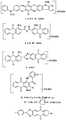
В качестве материала, из которого изготовлен дихроично поглощающий слой, в принципе может быть использован любой дихроично поглощающий материал, который может быть выполнен в виде слоя, толщина которого сравнима с длиной волны, в частности равна λ/4. Однако наиболее целесообразно использовать молекулярно ориентированный органический краситель, находящийся в лиотропном жидкокристаллическом состоянии, выбранный из ряда формул, приведенных в конце описания. As the material from which the dichroic absorbing layer is made, in principle, any dichroic absorbing material can be used, which can be made in the form of a layer whose thickness is comparable with the wavelength, in particular, equal to λ / 4. However, it is most advisable to use a molecularly oriented organic dye in a lyotropic liquid crystal state, selected from a number of formulas given at the end of the description.
Указанные органические красители позволяют осуществлять ориентацию молекул дихроичного красителя непосредственно в процессе нанесения слоя. Таким образом значительно упрощается технологический процесс получения дихроичного поляризатора и, как следствие, уменьшается его стоимость. These organic dyes allow the orientation of the dichroic dye molecules directly in the process of applying the layer. Thus, the technological process of obtaining a dichroic polarizer is greatly simplified and, as a result, its cost is reduced.
Для нанесения слоя, дихроично поглощающего электромагнитное излучение, могут быть применены следующие стандартные способы: нанесение валиком, ракельным ножом, ракелем в форме невращающегося цилиндра, нанесение с помощью щелевой фильеры и другие. The following standard methods can be applied for applying a layer that dichroically absorbs electromagnetic radiation: applying with a roller, doctor blade, doctor blade in the form of a non-rotating cylinder, applying with a slotted die and others.
На фиг.1 показана схема дихроичного поляризатора по прототипу; на фиг. 2 - схема дихроичного поляризатора отражательного типа по изобретению; на фиг. З - схема дихроичного поляризатора просветного типа по изобретению. Figure 1 shows a diagram of a dichroic polarizer of the prototype; in FIG. 2 is a diagram of a dichroic polarizer of the reflective type according to the invention; in FIG. Z is a diagram of a dichroic polarizer of the luminal type according to the invention.
На фиг. 1 изображена схема дихроичного поляризатора по прототипу, включающего слой 1, дихроично поглощающий электромагнитное излучение, нанесенный на подложку 2. Неполяризованное электромагнитное излучение 3 проходит слой 1, дихроично поглощающий электромагнитное излучение, превращаясь в линейно поляризованное электромагнитное излучение 4. Анализ свойств дихроичного поляризатора по прототипу показал, что при толщине слоя 1, дихроично поглощающего электромагнитное излучение в 50-100 нанометров, степень поляризации 80%, пропускание полезной поляризованной компоненты дихроичным поляризатором составляет 90%. При толщине слоя 1 в 500 нанометров степень поляризации 90%, пропускание полезной поляризованной компоненты составляет 80%. При толщине слоя 1 в 2000 нанометров степень поляризации 99%, пропускание полезной поляризованной компоненты дихроичным поляризатором составляет 50%. Таким образом, при увеличении степени поляризации в дихроичном поляризаторе по прототипу за счет увеличения толщины слоя 1, дихроично поглощающего электромагнитное излучение, значительно уменьшается пропускание полезной поляризованной компоненты. In FIG. 1 shows a diagram of a dichroic polarizer according to the prototype, including
На фиг. 2 изображена схема дихроичного поляризатора отражательного типа по изобретению, включающего слой 1, дихроично поглощающий электромагнитное излучение, слой 5, полностью отражающий электромагнитное излучение, и слой 6, частично отражающий электромагнитное излучение. Все слои последовательно нанесены на подложку 2. In FIG. 2 is a diagram of a reflective type dichroic polarizer according to the invention, including a
Работу предлагаемого дихроичного отражательного поляризатора можно пояснить следующим образом. Неполяризованное электромагнитное излучение состоит из двух линейно поляризованных компонент 7 и 8, плоскости поляризации которых взаимно перпендикулярны (эти две компоненты условно разнесены на фиг. 2 и фиг. З для наглядности и лучшего понимания). Поглощаемая и не используемая в дальнейшем компонента 7, поляризованная параллельно оси поглощения слоя 1, дихроично поглощающего электромагнитное излучение, частично отражается от слоя 6, частично отражающего электромагнитное излучение, образуя луч 9. Другая часть энергии компоненты 7, проходя через слой 1, дихроично поглощающий электромагнитное излучение, и, отражаясь от слоя 5, полностью отражающего электромагнитное излучение, проходит еще раз слой 1 и затем слой 6, образуя луч 10. Отраженные лучи 9 и 10 поляризованы так же, как и входящая компонента 7. Толщина слоя 1 выбирается такой, чтобы оптическая разность хода для лучей 9 и 10 составляла нечетное число полуволн поляризуемого электромагнитного излучения, где длина волны соответствует середине используемого спектрального диапазона. В этом случае результатом интерференции лучей 9 и 10 является их взаимное ослабление и в оптимальном варианте их полное гашение. Полное гашение лучей 9 и 10 достигается, если интенсивности (амплитуды) лучей 9 и 10 одинаковы или близки по величине, что может быть достигнуто оптимальным подбором коэффициентов отражения от отражающих слоев 5 и 6. Отражающие слои 5 и 6 могут быть выполнены металлическими или диэлектрическими и быть однослойными или многослойными. The work of the proposed dichroic reflective polarizer can be explained as follows. Non-polarized electromagnetic radiation consists of two linearly
Другая линейно поляризованная компонента 8, не поглощаемая в слое 1 и используемая в дальнейшем, которая поляризована перпендикулярно оси поглощения слоя 1, частично отражается от слоя 6, частично отражающего электромагнитное излучение, образуя луч 11. Другая часть энергии компоненты 8, проходя через слой 1, дихроично поглощающий электромагнитное излучение, и, отражаясь от слоя 5, проходит еще раз слой 1 и затем слой 6, образуя луч 12. Отраженные лучи 11 и 12 поляризованы так же, как и входящая компонента 8. В результате интерференции лучи 11 и 12 ослабляются значительно меньше, чем лучи 9 и 10. Это связано с тем, что их интенсивности значительно различаются за счет пренебрежимо малого поглощения луча 12 в слое 1. Another linearly
Таким образом, в результате различной степени ослабления поглощаемой и непоглощаемой компонент в выходящем из поляризатора излучении уменьшается доля одной (поглощаемой) линейно-поляризованной компоненты по отношению к другой (поглощаемой) компоненты, поляризованной ортогонально по отношению к поглощаемой компоненте, что приводит к значительному увеличению степени поляризации. Thus, as a result of varying degrees of attenuation of the absorbed and nonabsorbed components in the radiation leaving the polarizer, the fraction of one (absorbed) linearly polarized component decreases with respect to another (absorbed) component polarized orthogonally with respect to the absorbed component, which leads to a significant increase in the degree polarization.
На фиг. 3 изображена схема дихроичного поляризатора пропускающего типа по изобретению, включающего слой 1, дихроично поглощающий электромагнитное излучение, и слои 6 и 13, частично отражающие электромагнитное излучение. Все слои нанесены на подложку 2. In FIG. 3 is a schematic diagram of a dichroic polarizer of the transmission type according to the invention, including a
Работа дихроичного поляризатора электромагнитного излучения пропускающего типа поясняется следующим образом. The operation of the dichroic polarizing electromagnetic radiation transmitting type is illustrated as follows.
Неполяризованное электромагнитное излучение состоит из двух линейно поляризованных компонент 7 и 8, плоскости поляризации которых взаимно перпендикулярны. Обе эти компоненты проходят через слой 6, частично отражающий электромагнитное излучение, а затем через слой 1, дихроично поглощающий электромагнитное излучение. Часть энергии компонент 7 и 8 проходит через слой 13, частично отражающий электромагнитное излучение, и образует соответственно лучи 14 и 15. Другая часть энергии компонент 7 и 8 отражается от слоя 13, частично отражающего электромагнитное излучение, проходит слой 1, отражается от слоя 6, еще раз проходит слои 1 и 13 и образует соответственно лучи 16 и 17. Лучи 15 и 17 поляризованы так же, как и входящая компонента 8, а именно перпендикулярно оси поглощения. Лучи 14 и 16 поляризованы так же, как и входящая компонента 7, а именно параллельно оси поглощения. Unpolarized electromagnetic radiation consists of two linearly
Результатом интерференции поглощаемых в слое 1 лучей 14 и 16 является их взаимное ослабление и в оптимальном варианте их полное гашение. Полное гашение лучей 14 и 16 достигается, если интенсивности (амплитуды) лучей 14 и 16 одинаковы или близки по величине, что может быть достигнуто оптимальным подбором коэффициентов отражения от отражающих слоев 6 и 13. Отражающие слои 6 и 13 могут быть выполнены металлическими или диэлектрическими и быть однослойными или многослойными. The result of interference of
В результате интерференции непоглощаемые в слое 1 лучи 15 и 17 взаимно ослабляются значительно меньше, чем лучи 14 и 16. Это связано с тем, что их интенсивности значительно различаются за счет пренебрежимо малого поглощения лучей 15 и 17 в слое 1. As a result of interference, rays 15 and 17 that are not absorbed in
Таким образом в результате различной степени ослабления поглощаемой и непоглощаемой компонент в выходящем из поляризатора излучении уменьшается доля одной (поглощаемой) линейно-поляризованной компоненты по отношению к другой (поглощаемой) компоненты, поляризованной ортогонально по отношению к поглощаемой компоненте, что приводит к значительному увеличению степени поляризации. Thus, as a result of a different degree of attenuation of the absorbed and nonabsorbed components in the radiation leaving the polarizer, the fraction of one (absorbed) linearly polarized component decreases with respect to the other (absorbed) component polarized orthogonally with respect to the absorbed component, which leads to a significant increase in the degree of polarization .
Ниже даны примеры возможного выполнения дихроичного поляризатора. The following are examples of the possible implementation of the dichroic polarizer.
Пример 1. Дихроичный поляризатор отражательного типа по изобретению (фиг. 2) для поляризации видимого (светового) диапазона длин волн, т.е. для области длин волн 400-700 нанометров изготовлен следующим образом. На стеклянную подложку нанесены последовательно алюминиевый, сильно отражающий слой толщиной 100 нанометров (нанесенный с помощью термического испарения в вакууме), затем слой, дихроично поглощающий электромагнитное излучение толщиной 130 нм и изготовленный из смеси красителей формул I, II, III, и затем слой, частично отражающий электромагнитное излучение, толщиной 2 нанометра, выполненный из алюминия. Example 1. The dichroic polarizer of the reflective type according to the invention (Fig. 2) for polarization of the visible (light) wavelength range, i.e. for the wavelength region of 400-700 nanometers is made as follows. On a glass substrate, an aluminum, highly reflective layer 100 nm thick (deposited by thermal evaporation in vacuum) is successively applied, then a layer dichroically absorbing electromagnetic radiation 130 nm thick and made from a mixture of dyes of the formulas I, II, III, and then partially reflecting electromagnetic radiation, 2 nanometers thick, made of aluminum.
Измерения показали, поляризующая способность в изготовленном дихроичном поляризаторе составляет 92% , а отражение полезной поляризованной компоненты дихроичным поляризатором составляет 90%. Поляризующая способность в поляризаторе по прототипу, изготовленном из тех же красителей и той же толщины, нанесенном на зеркало для корректности сравнения, составил 80%, а отражение полезной поляризованной компоненты дихроичным поляризатором 90%. The measurements showed that the polarizing ability in the manufactured dichroic polarizer is 92%, and the reflection of the useful polarized component by the dichroic polarizer is 90%. The polarizing ability in the polarizer according to the prototype made of the same dyes and the same thickness deposited on the mirror for correct comparison was 80%, and the reflection of the useful polarized component by the dichroic polarizer was 90%.
Пример 2. Дихроичный поляризатор электромагнитного излучения отражательного типа (фиг. 2) для поляризации диапазона длин волн 490 - 510 нанометров изготовлен следующим образом. На стеклянную пластину нанесены последовательно сильно отражающий слой с коэффициентом отражения 98% в области длин волн 490 - 510 нанометров в виде многослойного диэлектрического покрытия, изготовленного из чередующихся слоев MgF2 и криолита. Затем на этот сильно отражающий слой нанесен слой, дихроично поглощающий электромагнитное излучение, толщиной 125 нм и изготовленный из ориентированного красителя формулы II, и затем слой, частично отражающий электромагнитное излучение с коэффициентом отражения 28% также изготовленный из слоев MgF2 и криолита.Example 2. The dichroic polarizer of electromagnetic radiation of the reflective type (Fig. 2) for polarization of the wavelength range of 490 - 510 nanometers is made as follows. A strongly reflecting layer with a reflection coefficient of 98% in the wavelength range of 490-510 nanometers in the form of a multilayer dielectric coating made of alternating layers of MgF2 and cryolite is sequentially applied to the glass plate. Then, a 125 nm thick dichroically absorbing electromagnetic radiation layer made of an oriented dye of formula II is applied to this highly reflective layer, and then a layer partially reflecting electromagnetic radiation with a reflection coefficient of 28% also made of MgF2 and cryolite layers.
Измерения показали, что поляризующая способность в изготовленном дихроичном поляризаторе составляет 95% в области длин волн 490 - 510 нанометров при отражении полезной поляризованной компоненты дихроичным поляризатором 85%. Поляризующая способность в поляризаторе по прототипу, изготовленном из того же красителя и той же толщины, нанесенном на зеркало для корректности сравнения, составила 85%, при отражении полезной поляризованной компоненты дихроичным поляризатором 90%. Measurements showed that the polarizing ability in the fabricated dichroic polarizer is 95% in the wavelength range of 490 - 510 nanometers with the reflection of the useful polarized component by the dichroic polarizer 85%. The polarizing ability in the polarizer according to the prototype made of the same dye and the same thickness deposited on the mirror for correct comparison was 85%, while the useful polarized component was reflected with a 90% dichroic polarizer.
Пример З. Дихроичный поляризатор электромагнитного излучения просветного типа (фиг. З) для поляризации в области длин волн 620 - 640 нанометров изготовлен следующим образом. На стеклянную пластину нанесены последовательно алюминиевый, частично отражающий слой толщиной 20 нанометров (нанесенный с помощью термического испарения в вакууме), затем слой, дихроично поглощающий электромагнитное излучение толщиной 155 нм и изготовленный из ориентированного красителя формулы IV, и затем второй слой, частично отражающий электромагнитное излучение, толщиной 20 нанометров, выполненный из алюминия. Example Z. The dichroic polarizer of electromagnetic radiation of the translucent type (Fig. C) for polarization in the wavelength range of 620 - 640 nanometers is made as follows. A 20-nanometer-thick aluminum partially reflective layer (deposited by thermal evaporation in vacuum) is sequentially applied to the glass plate, then a layer dichroically absorbing electromagnetic radiation 155 nm thick and made of an oriented dye of formula IV, and then a second layer partially reflecting electromagnetic radiation , 20 nanometers thick, made of aluminum.
Измерения показали, поляризующая способность в изготовленном дихроичном поляризаторе составляет 98%, при отражении полезной поляризованной компоненты дихроичным поляризатором 80%. Поляризующая способность в поляризаторе по прототипу, изготовленном из того же красителя и той же толщины составила 86%, при пропускании полезной поляризованной компоненты дихроичным поляризатором 82%. The measurements showed that the polarizing ability in the manufactured dichroic polarizer is 98%, while the reflection of the useful polarized component by the dichroic polarizer is 80%. The polarizing ability in the polarizer according to the prototype made of the same dye and the same thickness was 86%, while transmitting the useful polarized component with a dichroic polarizer 82%.
Пример 4. Дихроичный поляризатор электромагнитного излучения просветного типа по изобретению (фиг. З) для поляризации ближнего инфракрасного диапазона длин волн изготовлен следующим образом. На стеклянную пластину нанесены последовательно частично отражающий слой с коэффициентом отражения 40 - 55% в области длин волн 700 - 1200 нанометров в виде многослойного диэлектрического покрытия, изготовленного из слоев сернистого цинка и аммония фосфорнокислого. Затем нанесен слой, дихроично поглощающий электромагнитное излучение толщиной 250 нм и изготовленный из ориентированного красителя формулы X, и затем слой, частично отражающий электромагнитное излучение с коэффициентом отражения 28%, также изготовленный из слоев сернистого цинка и аммония фосфорнокислого. Example 4. The dichroic polarizer of electromagnetic radiation of the translucent type according to the invention (Fig. C) for polarization of the near infrared wavelength range is made as follows. A partially reflecting layer with a reflection coefficient of 40–55% in the wavelength range of 700–1200 nanometers in the form of a multilayer dielectric coating made of layers of zinc sulfide and ammonium phosphate is sequentially applied to the glass plate. Then a layer is applied that dichroically absorbs electromagnetic radiation with a thickness of 250 nm and is made from an oriented dye of the formula X, and then a layer partially reflecting electromagnetic radiation with a reflection coefficient of 28%, also made from layers of zinc sulfide and ammonium phosphate.
Измерения показали, поляризующая способность в изготовленном дихроичном поляризаторе составляет 92% в области длин волн 700 - 1200 нанометров при отражении полезной поляризованной компоненты дихроичным поляризатором 80%. Поляризующая способность в поляризаторе по прототипу, изготовленном из того же красителя и той же толщины составила 75%, при отражении полезной поляризованной компоненты дихроичным поляризатором 80%. The measurements showed that the polarizing ability in the fabricated dichroic polarizer is 92% in the wavelength range of 700 - 1200 nanometers with the reflection of the useful polarized component by a dichroic polarizer of 80%. The polarizing ability in the polarizer according to the prototype made of the same dye and the same thickness was 75%, with the reflection of the useful polarized component by the dichroic polarizer 80%.
Таким образом, во всех приведенных примерах достигается повышение эффективности дихроичного поляризатора за счет увеличения степени поляризации выходящего из него электромагнитного излучения, при сохранении высокого коэффициента пропускания (отражения) для непоглощаемой компоненты. Thus, in all the examples cited, an increase in the efficiency of the dichroic polarizer is achieved by increasing the degree of polarization of the electromagnetic radiation emerging from it, while maintaining a high transmittance (reflection) for the non-absorbable component.
Claims (6)
Translated fromRussianPriority Applications (7)
| Application Number | Priority Date | Filing Date | Title |
|---|---|---|---|
| RU97113613/28ARU2124746C1 (en) | 1997-08-11 | 1997-08-11 | Dichroic polarizer |
| CN98809519.XACN1109903C (en) | 1997-08-11 | 1998-08-03 | Dichroism polarizer |
| JP2000506552AJP3792510B2 (en) | 1997-08-11 | 1998-08-03 | Two-color polarizer |
| EP98940724AEP1014119B1 (en) | 1997-08-11 | 1998-08-03 | Dichroic polariser |
| PCT/RU1998/000251WO1999008140A1 (en) | 1997-08-11 | 1998-08-03 | Dichroic polariser |
| US09/485,329US6942925B1 (en) | 1997-08-11 | 1998-08-03 | Dichroic polarizer |
| DE69832185TDE69832185T2 (en) | 1997-08-11 | 1998-08-03 | DICHROIC POLARISATOR |
Applications Claiming Priority (1)
| Application Number | Priority Date | Filing Date | Title |
|---|---|---|---|
| RU97113613/28ARU2124746C1 (en) | 1997-08-11 | 1997-08-11 | Dichroic polarizer |
Publications (2)
| Publication Number | Publication Date |
|---|---|
| RU2124746C1true RU2124746C1 (en) | 1999-01-10 |
| RU97113613A RU97113613A (en) | 1999-03-27 |
Family
ID=20196160
Family Applications (1)
| Application Number | Title | Priority Date | Filing Date |
|---|---|---|---|
| RU97113613/28ARU2124746C1 (en) | 1997-08-11 | 1997-08-11 | Dichroic polarizer |
Country Status (7)
| Country | Link |
|---|---|
| US (1) | US6942925B1 (en) |
| EP (1) | EP1014119B1 (en) |
| JP (1) | JP3792510B2 (en) |
| CN (1) | CN1109903C (en) |
| DE (1) | DE69832185T2 (en) |
| RU (1) | RU2124746C1 (en) |
| WO (1) | WO1999008140A1 (en) |
Cited By (2)
| Publication number | Priority date | Publication date | Assignee | Title |
|---|---|---|---|---|
| RU2551469C2 (en)* | 2008-10-30 | 2015-05-27 | Пауэр Дженерейшн Текнолоджис Дивелопмент Фанд Л.П. | Toroid-shaped gas turbine of boundary layer |
| US10401032B2 (en) | 2008-10-30 | 2019-09-03 | Power Generation Technologies Development Fund, L.P. | Toroidal combustion chamber |
Families Citing this family (57)
| Publication number | Priority date | Publication date | Assignee | Title |
|---|---|---|---|---|
| RU2155978C2 (en)* | 1998-10-28 | 2000-09-10 | ОПТИВА, Инк. | Dichroic polarizer and method for its manufacturing |
| JP3741011B2 (en) | 2001-07-27 | 2006-02-01 | セイコーエプソン株式会社 | Liquid crystal display device and electronic device |
| RU2226708C2 (en) | 2001-09-21 | 2004-04-10 | ОПТИВА, Инк. | Liquid-crystal display with reflection polarizer |
| JP4201267B2 (en)* | 2001-09-21 | 2008-12-24 | 日東電工株式会社 | Liquid crystal display with reflective polarizing plate |
| IL148804A (en)* | 2002-03-21 | 2007-02-11 | Yaacov Amitai | Optical device |
| JP3765284B2 (en) | 2002-04-09 | 2006-04-12 | セイコーエプソン株式会社 | LIQUID CRYSTAL DISPLAY DEVICE, ITS MANUFACTURING METHOD, AND ELECTRONIC DEVICE |
| JP3858755B2 (en) | 2002-05-15 | 2006-12-20 | セイコーエプソン株式会社 | LIQUID CRYSTAL DISPLAY DEVICE, ITS MANUFACTURING METHOD, AND ELECTRONIC DEVICE |
| JP2004163581A (en)* | 2002-11-12 | 2004-06-10 | Konica Minolta Holdings Inc | Optical compensation film, polarizing plate and liquid crystal display device |
| US7144608B2 (en)* | 2003-01-24 | 2006-12-05 | Nitto Denko Corporation | Color correcting polarizer |
| CN100442090C (en)* | 2003-01-24 | 2008-12-10 | 日东电工株式会社 | Color Correcting Polarizers |
| US9096014B2 (en) | 2003-07-01 | 2015-08-04 | Transitions Optical, Inc. | Oriented polymeric sheets exhibiting dichroism and articles containing the same |
| US7256921B2 (en)* | 2003-07-01 | 2007-08-14 | Transitions Optical, Inc. | Polarizing, photochromic devices and methods of making the same |
| US10073264B2 (en) | 2007-08-03 | 2018-09-11 | Lumus Ltd. | Substrate-guide optical device |
| US10261321B2 (en) | 2005-11-08 | 2019-04-16 | Lumus Ltd. | Polarizing optical system |
| US20070211257A1 (en)* | 2006-03-09 | 2007-09-13 | Kearl Daniel A | Fabry-Perot Interferometer Composite and Method |
| CN102112913B (en)* | 2008-08-27 | 2013-10-09 | 夏普株式会社 | Electrode contact structure, liquid crystal display device having same, and method for manufacturing electrode contact structure |
| KR101592481B1 (en) | 2009-02-06 | 2016-02-05 | 삼성전자 주식회사 | Liquid crystal display and method of manufacturing the same |
| JP2010026529A (en)* | 2009-10-27 | 2010-02-04 | Nitto Denko Corp | Wide view angle polarization film for liquid crystal display, and wide view angle polarization tacky adhesive film for liquid crystal display |
| US9360596B2 (en) | 2013-04-24 | 2016-06-07 | Light Polymers Holding | Depositing polymer solutions to form optical devices |
| US9353092B2 (en) | 2013-06-27 | 2016-05-31 | University Of Notre Dame Du Lac | Synthesis and use of croconaine compounds |
| KR102114789B1 (en) | 2013-12-18 | 2020-05-26 | 삼성디스플레이 주식회사 | Polarizing plate, display device comprising the same and the fabrication method of the polarizing plate |
| IL232197B (en) | 2014-04-23 | 2018-04-30 | Lumus Ltd | Compact head-mounted display system |
| US9829617B2 (en) | 2014-11-10 | 2017-11-28 | Light Polymers Holding | Polymer-small molecule film or coating having reverse or flat dispersion of retardation |
| IL235642B (en) | 2014-11-11 | 2021-08-31 | Lumus Ltd | Compact head-mounted display system protected by a hyperfine structure |
| US9856172B2 (en) | 2015-08-25 | 2018-01-02 | Light Polymers Holding | Concrete formulation and methods of making |
| WO2018065975A1 (en) | 2016-10-09 | 2018-04-12 | Lumus Ltd | Aperture multiplier using a rectangular waveguide |
| KR20240160657A (en) | 2016-11-08 | 2024-11-11 | 루머스 리미티드 | Light-guide device with optical cutoff edge and corresponding production methods |
| CN108738358B (en) | 2017-02-22 | 2021-03-26 | 鲁姆斯有限公司 | Light guide optics |
| CN109416433B (en) | 2017-03-22 | 2021-06-01 | 鲁姆斯有限公司 | Overlapping Reflector Construction |
| IL251645B (en) | 2017-04-06 | 2018-08-30 | Lumus Ltd | Light-guide optical element and method of its manufacture |
| US10403435B2 (en) | 2017-12-15 | 2019-09-03 | Capacitor Sciences Incorporated | Edder compound and capacitor thereof |
| US10551544B2 (en) | 2018-01-21 | 2020-02-04 | Lumus Ltd. | Light-guide optical element with multiple-axis internal aperture expansion |
| US10962696B2 (en) | 2018-01-31 | 2021-03-30 | Light Polymers Holding | Coatable grey polarizer |
| MX2020012512A (en) | 2018-05-23 | 2021-02-16 | Lumus Ltd | Optical system including light-guide optical element with partially-reflective internal surfaces. |
| US11370914B2 (en) | 2018-07-24 | 2022-06-28 | Light Polymers Holding | Methods of forming polymeric polarizers from lyotropic liquid crystals and polymeric polarizers formed thereby |
| CN116184666A (en) | 2018-09-09 | 2023-05-30 | 鲁姆斯有限公司 | Optical system comprising a light-guiding optical element with two-dimensional expansion |
| MX2021008808A (en) | 2019-01-24 | 2021-08-24 | Lumus Ltd | Optical systems including loe with three stage expansion. |
| WO2020174433A1 (en) | 2019-02-28 | 2020-09-03 | Lumus Ltd. | Compact collimated image projector |
| EP3956604A4 (en) | 2019-04-15 | 2022-06-08 | Lumus Ltd. | PROCESS FOR MANUFACTURING AN OPTICAL LIGHT GUIDE ELEMENT |
| CA3137994A1 (en) | 2019-06-27 | 2020-12-30 | Lumus Ltd | Apparatus and methods for eye tracking based on eye imaging via a light-guide optical element |
| AU2020300121B2 (en) | 2019-07-04 | 2024-06-13 | Lumus Ltd. | Image waveguide with symmetric beam multiplication |
| KR20220035088A (en) | 2019-07-18 | 2022-03-21 | 루머스 리미티드 | Encapsulated light guide optics |
| TWI884834B (en) | 2019-12-05 | 2025-05-21 | 以色列商魯姆斯有限公司 | Optical device and method of fabricating optical device |
| US11523092B2 (en) | 2019-12-08 | 2022-12-06 | Lumus Ltd. | Optical systems with compact image projector |
| IL294151A (en) | 2019-12-30 | 2022-08-01 | Lumus Ltd | Optical systems including light-guiding optical elements with two-dimensional expansion |
| CN218848473U (en) | 2020-05-12 | 2023-04-11 | 鲁姆斯有限公司 | Equipment including projection optics and light guides |
| CN115176190B (en) | 2020-05-24 | 2024-07-09 | 鲁姆斯有限公司 | Composite light guide optical element |
| AU2021279462B2 (en) | 2020-05-24 | 2023-06-08 | Lumus Ltd. | Method of fabrication of compound light-guide optical elements |
| WO2022044006A1 (en) | 2020-08-26 | 2022-03-03 | Lumus Ltd. | Generation of color images using white light as source |
| KR20240006707A (en) | 2021-02-25 | 2024-01-15 | 루머스 리미티드 | Optical aperture multipliers having a rectangular waveguide |
| KR20230148324A (en) | 2021-03-01 | 2023-10-24 | 루머스 리미티드 | Optical system with compact coupling from projector to waveguide |
| TW202300988A (en) | 2021-05-19 | 2023-01-01 | 以色列商魯姆斯有限公司 | Active optical engine |
| KR102676604B1 (en) | 2021-07-04 | 2024-06-18 | 루머스 리미티드 | Display with stacked light guiding elements providing different parts of the field of view |
| US11796740B2 (en)* | 2021-07-30 | 2023-10-24 | Chiral Quantum Inc. | Optical device |
| KR20240046489A (en) | 2021-08-23 | 2024-04-09 | 루머스 리미티드 | Method for manufacturing composite light guiding optical elements with embedded coupling-in reflector |
| US12072520B2 (en) | 2021-11-11 | 2024-08-27 | Light Polymers Holding | Linear polarizers and methods of forming a linear polarizer |
| WO2024038458A1 (en) | 2022-08-18 | 2024-02-22 | Lumus Ltd. | Image projector with polarizing catadioptric collimator |
Citations (3)
| Publication number | Priority date | Publication date | Assignee | Title |
|---|---|---|---|---|
| SU1631488A1 (en)* | 1988-09-15 | 1991-02-28 | Предприятие П/Я Р-6681 | Method of manufacturing polarized ultraviolet light filters |
| US5122906A (en)* | 1989-06-20 | 1992-06-16 | The Dow Chemical Company | Thick/very thin multilayer reflective polymeric body |
| WO1995017692A1 (en)* | 1993-12-21 | 1995-06-29 | Minnesota Mining And Manufacturing Company | Reflective polarizer with brightness enhancement |
Family Cites Families (14)
| Publication number | Priority date | Publication date | Assignee | Title |
|---|---|---|---|---|
| JPS57208063A (en) | 1981-06-17 | 1982-12-21 | Japan Storage Battery Co Ltd | Lead storage battery comprising cell having electrolyte uniforming device |
| EP0098088B1 (en) | 1982-06-30 | 1987-03-11 | Teijin Limited | Optical laminar structure |
| FR2606418B1 (en)* | 1986-11-07 | 1994-02-11 | Commissariat A Energie Atomique | THERMALLY, ELECTRICALLY OR MAGNETICALLY CONTROLLED LYOTROPIC LIQUID CRYSTAL OPTICAL DEVICES |
| US5126880A (en)* | 1990-12-18 | 1992-06-30 | The Dow Chemical Company | Polymeric reflective bodies with multiple layer types |
| GB9309003D0 (en)* | 1993-04-30 | 1993-06-16 | Marconi Gec Ltd | Optical devices |
| RU2047643C1 (en)* | 1993-05-21 | 1995-11-10 | Хан Ир Гвон | Material for polarizing coating |
| US5673127A (en)* | 1993-12-01 | 1997-09-30 | Matsushita Electric Industrial Co., Ltd. | Display panel and display device using a display panel |
| US5828488A (en)* | 1993-12-21 | 1998-10-27 | Minnesota Mining And Manufacturing Co. | Reflective polarizer display |
| EP0736187B1 (en)* | 1993-12-21 | 2002-04-03 | Minnesota Mining And Manufacturing Company | Optical polarizer |
| TW270989B (en)* | 1994-11-22 | 1996-02-21 | Akzo Nobel Nv | Digital storage medium based on fabry-perot principle |
| US5686979A (en)* | 1995-06-26 | 1997-11-11 | Minnesota Mining And Manufacturing Company | Optical panel capable of switching between reflective and transmissive states |
| WO1997008692A1 (en)* | 1995-08-30 | 1997-03-06 | Akzo Nobel N.V. | Optical recording medium containing a thiophene squarilium or croconium dye |
| RU2120651C1 (en)* | 1996-04-15 | 1998-10-20 | Поларайзер Интернэшнл, ЛЛСи | Lcd indicator |
| DE69825251T2 (en) | 1997-12-16 | 2004-12-30 | Federalnoe Gosudarstvennoe Uni. Predpriyatie "Gosudarstvenny Nauchny Tsentr" Nauchno-Issledovatelsky Inst. Org. Poluprod... | POLARIZER AND LIQUID CRYSTAL DISPLAY ELEMENT |
- 1997
- 1997-08-11RURU97113613/28Apatent/RU2124746C1/ennot_activeIP Right Cessation
- 1998
- 1998-08-03CNCN98809519.XApatent/CN1109903C/ennot_activeExpired - Fee Related
- 1998-08-03DEDE69832185Tpatent/DE69832185T2/ennot_activeExpired - Fee Related
- 1998-08-03USUS09/485,329patent/US6942925B1/ennot_activeExpired - Fee Related
- 1998-08-03WOPCT/RU1998/000251patent/WO1999008140A1/enactiveIP Right Grant
- 1998-08-03EPEP98940724Apatent/EP1014119B1/ennot_activeExpired - Lifetime
- 1998-08-03JPJP2000506552Apatent/JP3792510B2/ennot_activeExpired - Fee Related
Patent Citations (3)
| Publication number | Priority date | Publication date | Assignee | Title |
|---|---|---|---|---|
| SU1631488A1 (en)* | 1988-09-15 | 1991-02-28 | Предприятие П/Я Р-6681 | Method of manufacturing polarized ultraviolet light filters |
| US5122906A (en)* | 1989-06-20 | 1992-06-16 | The Dow Chemical Company | Thick/very thin multilayer reflective polymeric body |
| WO1995017692A1 (en)* | 1993-12-21 | 1995-06-29 | Minnesota Mining And Manufacturing Company | Reflective polarizer with brightness enhancement |
Non-Patent Citations (1)
| Title |
|---|
| PCT WO 94/054934 A1, C 09 B 31/147.* |
Cited By (3)
| Publication number | Priority date | Publication date | Assignee | Title |
|---|---|---|---|---|
| RU2551469C2 (en)* | 2008-10-30 | 2015-05-27 | Пауэр Дженерейшн Текнолоджис Дивелопмент Фанд Л.П. | Toroid-shaped gas turbine of boundary layer |
| US9243805B2 (en) | 2008-10-30 | 2016-01-26 | Power Generation Technologies Development Fund, L.P. | Toroidal combustion chamber |
| US10401032B2 (en) | 2008-10-30 | 2019-09-03 | Power Generation Technologies Development Fund, L.P. | Toroidal combustion chamber |
Also Published As
| Publication number | Publication date |
|---|---|
| JP2001512845A (en) | 2001-08-28 |
| US6942925B1 (en) | 2005-09-13 |
| CN1109903C (en) | 2003-05-28 |
| JP3792510B2 (en) | 2006-07-05 |
| EP1014119A4 (en) | 2001-12-12 |
| CN1271422A (en) | 2000-10-25 |
| DE69832185T2 (en) | 2006-08-03 |
| EP1014119A1 (en) | 2000-06-28 |
| WO1999008140A1 (en) | 1999-02-18 |
| EP1014119B1 (en) | 2005-11-02 |
| DE69832185D1 (en) | 2005-12-08 |
Similar Documents
| Publication | Publication Date | Title |
|---|---|---|
| RU2124746C1 (en) | Dichroic polarizer | |
| US5912762A (en) | Thin film polarizing device | |
| US7859754B2 (en) | Wideband dichroic-filter design for LED-phosphor beam-combining | |
| US5296961A (en) | Dichroic optical filter | |
| CA2290860C (en) | Polarizing back-lighting system for direct view liquid crystal displays | |
| WO2020166691A1 (en) | Optical element, light-guide element, and image display element | |
| RU2225025C2 (en) | Liquid-crystal device for information display | |
| KR20060059992A (en) | Interference optical filter | |
| US7113337B2 (en) | Multilayer optical coating | |
| WO2007083158A2 (en) | Multilayer polarizer | |
| Gevorgyan | Chiral photonic crystals with an anisotropic defect layer: Oblique incidence | |
| US8879150B1 (en) | Optical thin-film polarizing bandpass filter | |
| US3887261A (en) | Low-loss reflection coatings using absorbing materials | |
| US20070195416A1 (en) | Interferential Optical Filter | |
| GB2384059A (en) | Pancake window optical device with thin film helicoidal bianisotropic medium | |
| WO2024185846A1 (en) | Liquid crystal polarization interference element, optical filter, and optical system | |
| KR100657725B1 (en) | Multilayer optical coating | |
| RU2001118989A (en) | Multilayer optical coating | |
| EP0845111B1 (en) | Thin film polarizing device | |
| RU2140094C1 (en) | Optical polarizer | |
| Gritz | Near-infrared (IR) polarizing glass | |
| Li | The design of optical thin film coatings with total and frustrated total internal reflection | |
| JPH03157621A (en) | Polarized light source device | |
| JPH04140714A (en) | Variable wavelength filter module | |
| Hodgkinson et al. | Review of birefringent and chiral optical interference coatings |
Legal Events
| Date | Code | Title | Description |
|---|---|---|---|
| MM4A | The patent is invalid due to non-payment of fees | Effective date:20050812 |