RU2123219C1 - Vibratory gyroscope - Google Patents
Vibratory gyroscopeDownload PDFInfo
- Publication number
- RU2123219C1 RU2123219C1RU97108216ARU97108216ARU2123219C1RU 2123219 C1RU2123219 C1RU 2123219C1RU 97108216 ARU97108216 ARU 97108216ARU 97108216 ARU97108216 ARU 97108216ARU 2123219 C1RU2123219 C1RU 2123219C1
- Authority
- RU
- Russia
- Prior art keywords
- electrodes
- solid
- pairs
- generator
- output
- Prior art date
Links
- 239000000919ceramicSubstances0.000claimsabstractdescription8
- 239000007787solidSubstances0.000claimsabstractdescription8
- 230000007704transitionEffects0.000claimsabstractdescription4
- 230000010355oscillationEffects0.000claimsdescription4
- 230000000694effectsEffects0.000abstractdescription8
- 230000036039immunityEffects0.000abstractdescription5
- 239000000126substanceSubstances0.000abstract1
- 239000003990capacitorSubstances0.000description9
- 239000000463materialSubstances0.000description6
- 230000035882stressEffects0.000description5
- 230000032683agingEffects0.000description2
- 238000005452bendingMethods0.000description2
- 238000010586diagramMethods0.000description2
- 230000035945sensitivityEffects0.000description2
- 230000009466transformationEffects0.000description2
- BQCADISMDOOEFD-UHFFFAOYSA-NSilverChemical compound[Ag]BQCADISMDOOEFD-UHFFFAOYSA-N0.000description1
- JRPBQTZRNDNNOP-UHFFFAOYSA-Nbarium titanateChemical compound[Ba+2].[Ba+2].[O-][Ti]([O-])([O-])[O-]JRPBQTZRNDNNOP-UHFFFAOYSA-N0.000description1
- 229910002113barium titanateInorganic materials0.000description1
- 238000006243chemical reactionMethods0.000description1
- 229910003460diamondInorganic materials0.000description1
- 239000010432diamondSubstances0.000description1
- 239000011263electroactive materialSubstances0.000description1
- 238000007731hot pressingMethods0.000description1
- 238000003754machiningMethods0.000description1
- 238000004519manufacturing processMethods0.000description1
- 238000000034methodMethods0.000description1
- 230000003534oscillatory effectEffects0.000description1
- 229910052709silverInorganic materials0.000description1
- 239000004332silverSubstances0.000description1
- 239000006104solid solutionSubstances0.000description1
- 239000002344surface layerSubstances0.000description1
- 230000001360synchronised effectEffects0.000description1
Images


Landscapes
- Gyroscopes (AREA)
Abstract
Description
Translated fromRussianИзобретение относится к электрическим приборам на твердом теле и предназначено для работы в качестве датчика угловой скорости подвижных объектов. The invention relates to electrical devices on a solid and is intended to work as a sensor for the angular velocity of moving objects.
Известен датчик угловой скорости для управляемых ракет ("Электроника", т. 46, N 9, 1973, стр. 17). Датчик содержит пьезоэлектрический электромеханический преобразователь, который приводит в движение поток газа, выполняющий ту же функцию, что и вращающийся ротор в электромеханических гироскопах. Угловая скорость подвижного объекта под влиянием силы Кориолиса вызывает отклонение газового потока, которое обнаруживается мостовым терморезистивным преобразователем. Датчик обладает высокой механической прочностью, позволяющей использовать его в ракетах, выстреливаемых из артиллерийского орудия. Однако чувствительность датчика недостаточна для применения его в большинстве навигационных систем. A known angular velocity sensor for guided missiles ("Electronics", t. 46, N 9, 1973, p. 17). The sensor contains a piezoelectric electromechanical transducer that drives a gas stream that performs the same function as a rotating rotor in electromechanical gyroscopes. The angular velocity of a moving object under the influence of the Coriolis force causes a deviation of the gas flow, which is detected by a bridge thermoresistive converter. The sensor has high mechanical strength, allowing it to be used in missiles fired from artillery guns. However, the sensitivity of the sensor is not sufficient for use in most navigation systems.
Наиболее близким аналогом является пьезоэлектрический датчик угловой скорости (а.с. N 265963 (СССР). Опалев В.Н., Шершун Е.Ф. и Кушко Н.И. Открытия. Изобретения. 1970, N 11). Устройство содержит Н-образный пьезоэлектрический элемент, состоящий из входного и выходного электромеханических преобразователей в виде плоских резонаторов, снабженных электродами, генератор электрических колебаний и электронный преобразователь для измерения выходного напряжения. Устройство компактно и обладает малым потреблением энергии. The closest analogue is the piezoelectric angular velocity sensor (A.S. N 265963 (USSR). Opalev V.N., Shershun E.F. and Kushko N.I. Discovery. Inventions. 1970, No. 11). The device contains an H-shaped piezoelectric element consisting of input and output electromechanical transducers in the form of flat resonators equipped with electrodes, an electric oscillation generator and an electronic transducer for measuring the output voltage. The device is compact and has low power consumption.
Датчик представляет собой пьезотрансформатор с коэффициентом трансформации, зависящим от угловой скорости и обладает недостатками пьезотрансформаторных устройств, в том числе зависимостью коэффициета трансформации от температуры и старением пьезоэлектрического материала, также приводящим к изменению чувствительности датчика. Кроме того, примененный метод амплитудной модуляции не обеспечивает достаточной помехоустойчивости устройства. The sensor is a piezotransformer with a transformation coefficient that depends on the angular velocity and has the disadvantages of piezotransformer devices, including the dependence of the transformation coefficient on temperature and the aging of the piezoelectric material, which also leads to a change in the sensitivity of the sensor. In addition, the applied method of amplitude modulation does not provide sufficient noise immunity of the device.
Заявляемый в качестве изобретения виброгироскоп позволяет значительно увеличить точность измерения угловой скорости за счет повышения стабильности и помехоустойчивости, и, следовательно, повысить точность навигационной системы с использованием предлагаемого виброгироскопа. Declared as an invention, the gyroscope can significantly increase the accuracy of measuring angular velocity by increasing stability and noise immunity, and, therefore, improve the accuracy of the navigation system using the proposed vibroscope.
Указанный технический эффект достигается тем, что в виброгироскопе, содержащем твердотельный элемент из сегнетоэлектрической керамики с электродами, первый генератор электрических колебаний и электронный преобразователь, твердотельный элемент выполнен из керамики с размытым фазовым переходом в виде монолитного стержня с крестообразным поперечным сечением, образованного пересечением двух пластин. На одну из пластин нанесены четыре пары электродов, причем две пары образованы сплошными электродами, нанесенными на противоположные поверхности пластины, а другие две пары электродов нанесены на одну из поверхностей пластины и выполнены в виде встречно-штыревых структур. Электронный преобразователь содержит второй и третий генераторы электрических колебаний, смеситель, детектор и индикатор. Две пары сплошных электродов соединены параллельно и подключены к выходу первого генератора. Одна из пар встречно-штыревых электродов подключена к частотно-задающей цепи второго генератора, другая пара встречно-штыревых электродов подключена к частотно-задающей цепи третьего генератора. Выходы второго и третьего генераторов подключены к входам смесителя, выход смесителя подключен к входу детектора, а выход детектора подключен к входу индикатора. The indicated technical effect is achieved by the fact that in a vibroscope containing a solid-state element made of ferroelectric ceramics with electrodes, a first generator of electrical vibrations and an electronic converter, the solid-state element is made of ceramics with a diffuse phase transition in the form of a monolithic rod with a cross-shaped cross section formed by the intersection of two plates. Four pairs of electrodes are deposited on one of the plates, and two pairs are formed by solid electrodes deposited on opposite surfaces of the plate, and the other two pairs of electrodes are deposited on one of the surfaces of the plate and are made in the form of interdigital structures. The electronic converter comprises a second and third electric oscillation generators, a mixer, a detector and an indicator. Two pairs of solid electrodes are connected in parallel and connected to the output of the first generator. One of the pairs of interdigital electrodes is connected to the frequency-setting circuit of the second generator, the other pair of interdigital electrodes is connected to the frequency-setting circuit of the third generator. The outputs of the second and third generators are connected to the inputs of the mixer, the output of the mixer is connected to the input of the detector, and the output of the detector is connected to the input of the indicator.
Создание виброгироскопа стало возможным благодаря совокупности новой конструкции твердотельного элемента, нового материала для его изготовления, нового принципа получения и электронного преобразования выходного сигнала. Выбранный в качестве электроактивного материала сегнетоэлектрик с размытым фазовым переходом находит применение в электрострикционных микропозиционерах (см. Веневцев Ю.Н. и др. Сегнето- и антисегнетоэлектрики семейства титаната бария. М., 1985, стр. 165). В заявляемом изобретении используется сочетание нескольких полезных свойств нового материала: малого старения из-за отсутствия доменной структуры, высокой электрострикционной деформации и обратного электрострикционного эффекта - существенной зависимости диэлектрической проницаемости от механического напряжения. Объединение этих эффектов в одной конструкции позволило создать гирочувствительный твердотельный элемент, обеспечивающий высокую стабильность - основной технический эффект изобретения. The creation of a vibro-gyroscope became possible due to the combination of a new design of a solid-state element, a new material for its manufacture, a new principle of obtaining and electronic conversion of the output signal. A ferroelectric with a diffuse phase transition selected as an electroactive material is used in electrostrictive micropositioners (see Venevtsev Yu.N. et al. Ferroelectric and antiferroelectrics of the barium titanate family. M., 1985, p. 165). In the claimed invention, a combination of several useful properties of the new material is used: low aging due to the absence of a domain structure, high electrostrictive deformation and reverse electrostrictive effect - a significant dependence of the dielectric constant on mechanical stress. The combination of these effects in one design made it possible to create a gyro-sensitive solid-state element that provides high stability - the main technical effect of the invention.
Симметричная конструкция твердотельного элемента позволяет разместить два встречно-штыревых конденсатора, емкость которых зависит от измеряемой угловой скорости, и включить их в дифференциальную схему частотной модуляции выходного сигнала, обеспечивающую высокую помехоустойчивость устройства - дополнительный технический эффект изобретения. Таким образом, совокупность существенных признаков изобретения: материаловедческих, конструкционных и схемотехнических, - значительно увеличивает точность навигационной системы, включающей заявляемый виброгироскоп. The symmetrical design of the solid-state element allows you to place two interdigital capacitors, the capacitance of which depends on the measured angular velocity, and include them in the differential circuit of the frequency modulation of the output signal, which provides high noise immunity of the device - an additional technical effect of the invention. Thus, the set of essential features of the invention: material science, structural and circuitry, significantly increases the accuracy of the navigation system, including the inventive vibroscope.
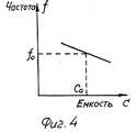
Сущность изобретения поясняется нижеследующим описанием и чертежами, где на фиг. 1 изображена структурная схема виброгироскопа и общий вид твердотельного элемента; на фиг. 2 изображена схема работы твердотельного элемента; на фиг. 3 - зависимость емкости встречно-штыревого конденсатора от механического напряжения; на фиг. 4 - зависимость частоты генератора от емкости конденсатора; на фиг. 5 - зависимость разностной частоты смесителя от угловой скорости. The invention is illustrated by the following description and drawings, where in FIG. 1 shows a structural diagram of a vibroscope and a general view of a solid-state element; in FIG. 2 shows a diagram of the operation of a solid-state element; in FIG. 3 - dependence of the capacitance of an interdigital capacitor on mechanical stress; in FIG. 4 - dependence of the frequency of the generator on the capacitance of the capacitor; in FIG. 5 - dependence of the difference frequency of the mixer on the angular velocity.
Виброгироскоп содержит монолитный керамический элемент 1 с крестообразным поперечным сечением. На противоположные поверхности одной из пластин, образующих элемент 1, нанесены две противолежащие пары сплошных электродов 2, 3 и 4, 5, симметричные относительно другой пластины (см. фиг. 1). На одной из поверхностей этой же пластины нанесены другие две пары электродов гребенчатой формы 6, 7 и 8, 9, каждая из которых образует встречно-штыревую структуру. The vibroscope contains a monolithic ceramic element 1 with a cross-shaped cross section. On the opposite surfaces of one of the plates forming the element 1, two opposite pairs of
Виброгироскоп содержит также генератор 10 и электронный преобразователь 11, включающий генераторы 12 и 13, смеситель 14, детектор 15 и индикатор 16, а также корпус 17. The vibroscope also contains a generator 10 and an electronic transducer 11, including generators 12 and 13, a mixer 14, a detector 15 and an indicator 16, as well as a housing 17.
Две пары электродов 2, 3 и 4, 5 соединены параллельно и подключены к выходу генератора электрических колебаний 10. Две пары встречно-штыревых электродов 6, 7 и 8, 9 включены в частотно-задающие цепи генераторов 12 и 13, соответственно. Выходы генераторов 12 и 13 подключены к входам смесителя 14, выход смесителя 14 соединен с входом детектора 15, выход детектора 15 соединен с входом индикатора 16. Пластина твердотельного элемента 1, свободная от электродов, жестко закреплена в корпусе 17, в котором расположены также генератор 10 и электронный преобразователь 11. Two pairs of
Монолитный керамический элемент 1 выполнен из сегнетоэлектрической керамики на основе твердого раствора магнониобата-титаната свинца, изготовленной методом горячего прессования. Механическая обработка элемента 1 выполнена шлифованием при помощи алмазных дисков. Электроды нанесены путем вжигания серебросодержащей пасты. The monolithic ceramic element 1 is made of ferroelectric ceramics based on a solid solution of lead magnoniobate-titanate made by hot pressing. The machining of the element 1 is performed by grinding with diamond discs. The electrodes are deposited by burning silver-containing paste.
Виброгироскоп работает следующим образом. С выхода генератора 10 электрические колебания поступают на электроды 2, 3, 4, 5 твердотельного элемента 1. За счет электрострикционного эффекта в элементе 1 возникают механические колебания с частотой, вдвое превышающей частоту электрических колебаний. Возникающие при этом динамические механические напряжения вызывают, в результате обратного электрострикционного эффекта, изменение диэлектрической проницаемости материала элемента 1. Емкость встречно-штыревых конденсаторов C67 и C89, образованных, соответственно, электродами 6, 7 и 8, 9, определяется, в основном, диэлектрической проницаемостью приповерхностного слоя материала, и ее зависимость от механического напряжения представлена на фиг. 3.Vibroscope works as follows. From the output of the generator 10, electrical vibrations arrive at the
При отсутствии вращения устройства вокруг оси Z (см. фиг. 1), т. е. при нулевой угловой скорости ω = 0 (см. фиг. 2 а) в элементе 1 происходят только линейные колебания вдоль оси X. В каждый момент времени механические напряжения в области конденсаторов C67 и C89 одинаковы по знаку и величине. В этом случае происходят синхронные и одинаковые изменения емкости конденсаторов C67 и C89. Конденсаторы C67 и C89, включенные в частотно-задающие цепи, изменяют частоту генераторов 12 и 13 на одинаковую величину (см. фиг. 4). В результате на выходе смесителя 14 разностная частота равна нулю. Равны нулю также выходной сигнал детектора 15 и показания индикатора 16.In the absence of rotation of the device around the Z axis (see Fig. 1), i.e., at zero angular velocity ω = 0 (see Fig. 2 a), only linear vibrations along the X axis occur in element 1. At each moment of time, mechanical the voltages in the region of the capacitors C67 and C89 are the same in sign and magnitude. In this case, synchronous and identical changes in the capacitance of the capacitors C67 and C89 occur. Capacitors C67 and C89 included in the frequency-setting circuit change the frequency of the generators 12 and 13 by the same amount (see Fig. 4). As a result, at the output of the mixer 14, the difference frequency is zero. The output signal of the detector 15 and the readings of the indicator 16 are also equal to zero.
Вращение устройства вокруг оси Z с угловой скоростью ω(ω ≠ 0 на фиг. 2 б, в) вызывает появление Кориолисовой силы инерции Fk, воздействующей на элемент 1 перпендикулярно направлению линейного движения, Fk= 2mωVx, где m и Vk масса и линейная скорость элемента объема (см. Яворский Б.М., Детлаф А.А. Справочник по физике. М. , 1990, стр. 86). В этом случае к колебательному линейному движению элемента 1 добавляются изгибные колебания элемента 1 (см. фиг. 2).The rotation of the device around the Z axis with an angular velocity ω (ω ≠ 0 in Fig. 2 b, c) causes the appearance of the Coriolis force of inertia Fk acting on element 1 perpendicular to the direction of linear motion, Fk = 2mωVx , where m and Vk are masses and linear velocity of a volume element (see. Yavorsky BM, Detlaf AA. Handbook of Physics. M., 1990, p. 86). In this case, bending vibrations of the element 1 are added to the oscillatory linear motion of the element 1 (see Fig. 2).
Изгибные механические напряжения в области конденсаторов C67 и C89 противоположны по знаку и, следовательно, вызывают противоположные по знаку изменения емкости конденсаторов C67 и C89 от среднего значения C0. В свою очередь, частота генераторов 12 и 13 изменяется в противоположные стороны от среднего значения f0. В результате разностная частота на выходе смесителя 14 равна сумме отклонений частоты генераторов 12 и 13 и линейно зависит от угловой скорости ω (см. фиг. 5). Сигнал с выхода смесителя 14 может служить выходным сигналом виброгироскопа в цифровой системе управления. В аналоговой системе управления частотный сигнал детектируется детектором 15 и регистрируется индикатором 16, показания которого пропорциональны измеряемой угловой скорости.Bending mechanical stresses in the region of the capacitors C67 and C89 are opposite in sign and, therefore, cause opposite sign changes in the capacitance of the capacitors C67 and C89 from the average value of C0 . In turn, the frequency of the generators 12 and 13 changes in opposite directions from the average value of f0 . As a result, the difference frequency at the output of the mixer 14 is equal to the sum of the frequency deviations of the generators 12 and 13 and linearly depends on the angular velocity ω (see Fig. 5). The signal from the output of the mixer 14 can serve as the output signal of the vibroscope in a digital control system. In an analog control system, a frequency signal is detected by the detector 15 and registered by the indicator 16, the readings of which are proportional to the measured angular velocity.
Предлагаемый виброгироскоп позволяет увеличить точность навигационной системы за счет повышения стабильности и помехоустойчивости и может быть применен в тех случаях, когда использование гироскопов, основанных на других физических принципах, экономически нецелесообразно или неприемлемо по массогабаритным характеристикам. Эффективно применение нового виброгироскопа в компактных системах навигации и автоматического управления наземными транспортными средствами и другими подвижными объектами. The proposed vibroscope allows you to increase the accuracy of the navigation system by increasing stability and noise immunity and can be applied in cases where the use of gyroscopes based on other physical principles is not economically feasible or unacceptable in terms of weight and size characteristics. Effectively applying the new vibroscope in compact navigation systems and automatic control of ground vehicles and other moving objects.
Claims (1)
Translated fromRussianPriority Applications (1)
| Application Number | Priority Date | Filing Date | Title |
|---|---|---|---|
| RU97108216ARU2123219C1 (en) | 1997-05-20 | 1997-05-20 | Vibratory gyroscope |
Applications Claiming Priority (1)
| Application Number | Priority Date | Filing Date | Title |
|---|---|---|---|
| RU97108216ARU2123219C1 (en) | 1997-05-20 | 1997-05-20 | Vibratory gyroscope |
Publications (2)
| Publication Number | Publication Date |
|---|---|
| RU2123219C1true RU2123219C1 (en) | 1998-12-10 |
| RU97108216A RU97108216A (en) | 1999-05-20 |
Family
ID=20193107
Family Applications (1)
| Application Number | Title | Priority Date | Filing Date |
|---|---|---|---|
| RU97108216ARU2123219C1 (en) | 1997-05-20 | 1997-05-20 | Vibratory gyroscope |
Country Status (1)
| Country | Link |
|---|---|
| RU (1) | RU2123219C1 (en) |
Cited By (14)
| Publication number | Priority date | Publication date | Assignee | Title |
|---|---|---|---|---|
| RU2260828C1 (en)* | 2004-04-07 | 2005-09-20 | Государственное образовательное учреждение высшего профессионального образования "Ростовский Государственный Университет" (РГУ) | Solid-state actuator |
| RU2310165C1 (en)* | 2006-03-29 | 2007-11-10 | Георгий Владимирович Анцев | Surface acoustic wave operated gyroscope |
| RU2329466C1 (en)* | 2006-11-29 | 2008-07-20 | Владимир Сергеевич Богословский | Gyroscope operating at acoustic surface waves |
| RU2335739C1 (en)* | 2007-04-19 | 2008-10-10 | Владимир Сергеевич Богословский | Sensitive element of gyroscope on surface acoustic waves |
| RU2335738C1 (en)* | 2007-05-14 | 2008-10-10 | Владимир Сергеевич Богословский | Sensitive element of resonant gyroscope on surface acoustic waves |
| RU2345446C1 (en)* | 2007-05-14 | 2009-01-27 | Владимир Сергеевич Богословский | Sensitive element of resonant gyroscope on surface acoustic waves with driver |
| RU2347189C1 (en)* | 2007-07-16 | 2009-02-20 | Владимир Сергеевич Богословский | Resonant gyroscope on superficial ultrasonic waves with partitioning of frequencies |
| RU2357212C1 (en)* | 2007-11-12 | 2009-05-27 | Владимир Сергеевич Богословский | Electronic gyro |
| RU2359275C1 (en)* | 2007-11-06 | 2009-06-20 | Владимир Сергеевич Богословский | Angular rate measuring method (versions) |
| RU2387998C1 (en)* | 2008-11-13 | 2010-04-27 | Государственное образовательное учреждение высшего профессионального образования "Санкт-Петербургский государственный электротехнический университет "ЛЭТИ" | Device for angular velocity measurement |
| RU2387951C1 (en)* | 2009-03-17 | 2010-04-27 | Открытое акционерное общество "Авангард" | Twist gyroscope |
| RU2389000C1 (en)* | 2009-03-25 | 2010-05-10 | ОАО "Авангард" | Micro-acoustic-electromechanical gyroscope and operation method thereof |
| RU2390727C1 (en)* | 2009-03-17 | 2010-05-27 | ОАО "Авангард" | Gyroscope operating on acoustic surface waves |
| RU2390729C2 (en)* | 2007-12-20 | 2010-05-27 | Владимир Сергеевич Богословский | Piezoelectric gyroscope |
Citations (4)
| Publication number | Priority date | Publication date | Assignee | Title |
|---|---|---|---|---|
| US4653325A (en)* | 1984-03-02 | 1987-03-31 | Kabushikikaisha Tokyo Keiki | Gyro apparatus |
| WO1995021464A1 (en)* | 1994-02-04 | 1995-08-10 | Maxtor Corporation | Rotational shock sensor |
| US5479822A (en)* | 1992-10-16 | 1996-01-02 | Murata Manufacturing Co., Ltd. | Casing for a vibratory gyroscope |
| RU2064682C1 (en)* | 1993-09-28 | 1996-07-27 | Владимир Михайлович Ачильдиев | Micromechanical vibratory gyroscope-accelerometer |
- 1997
- 1997-05-20RURU97108216Apatent/RU2123219C1/enactive
Patent Citations (4)
| Publication number | Priority date | Publication date | Assignee | Title |
|---|---|---|---|---|
| US4653325A (en)* | 1984-03-02 | 1987-03-31 | Kabushikikaisha Tokyo Keiki | Gyro apparatus |
| US5479822A (en)* | 1992-10-16 | 1996-01-02 | Murata Manufacturing Co., Ltd. | Casing for a vibratory gyroscope |
| RU2064682C1 (en)* | 1993-09-28 | 1996-07-27 | Владимир Михайлович Ачильдиев | Micromechanical vibratory gyroscope-accelerometer |
| WO1995021464A1 (en)* | 1994-02-04 | 1995-08-10 | Maxtor Corporation | Rotational shock sensor |
Cited By (14)
| Publication number | Priority date | Publication date | Assignee | Title |
|---|---|---|---|---|
| RU2260828C1 (en)* | 2004-04-07 | 2005-09-20 | Государственное образовательное учреждение высшего профессионального образования "Ростовский Государственный Университет" (РГУ) | Solid-state actuator |
| RU2310165C1 (en)* | 2006-03-29 | 2007-11-10 | Георгий Владимирович Анцев | Surface acoustic wave operated gyroscope |
| RU2329466C1 (en)* | 2006-11-29 | 2008-07-20 | Владимир Сергеевич Богословский | Gyroscope operating at acoustic surface waves |
| RU2335739C1 (en)* | 2007-04-19 | 2008-10-10 | Владимир Сергеевич Богословский | Sensitive element of gyroscope on surface acoustic waves |
| RU2335738C1 (en)* | 2007-05-14 | 2008-10-10 | Владимир Сергеевич Богословский | Sensitive element of resonant gyroscope on surface acoustic waves |
| RU2345446C1 (en)* | 2007-05-14 | 2009-01-27 | Владимир Сергеевич Богословский | Sensitive element of resonant gyroscope on surface acoustic waves with driver |
| RU2347189C1 (en)* | 2007-07-16 | 2009-02-20 | Владимир Сергеевич Богословский | Resonant gyroscope on superficial ultrasonic waves with partitioning of frequencies |
| RU2359275C1 (en)* | 2007-11-06 | 2009-06-20 | Владимир Сергеевич Богословский | Angular rate measuring method (versions) |
| RU2357212C1 (en)* | 2007-11-12 | 2009-05-27 | Владимир Сергеевич Богословский | Electronic gyro |
| RU2390729C2 (en)* | 2007-12-20 | 2010-05-27 | Владимир Сергеевич Богословский | Piezoelectric gyroscope |
| RU2387998C1 (en)* | 2008-11-13 | 2010-04-27 | Государственное образовательное учреждение высшего профессионального образования "Санкт-Петербургский государственный электротехнический университет "ЛЭТИ" | Device for angular velocity measurement |
| RU2387951C1 (en)* | 2009-03-17 | 2010-04-27 | Открытое акционерное общество "Авангард" | Twist gyroscope |
| RU2390727C1 (en)* | 2009-03-17 | 2010-05-27 | ОАО "Авангард" | Gyroscope operating on acoustic surface waves |
| RU2389000C1 (en)* | 2009-03-25 | 2010-05-10 | ОАО "Авангард" | Micro-acoustic-electromechanical gyroscope and operation method thereof |
Similar Documents
| Publication | Publication Date | Title |
|---|---|---|
| RU2123219C1 (en) | Vibratory gyroscope | |
| US4654663A (en) | Angular rate sensor system | |
| Söderkvist | Micromachined gyroscopes | |
| US4381672A (en) | Vibrating beam rotation sensor | |
| US5375336A (en) | Gyro-compass | |
| GB2158579A (en) | Angular rate sensor system | |
| CN101135559A (en) | Dual-mass vibrating silicon microgyroscope | |
| JPH063455B2 (en) | Vibrating gyro | |
| JP5259598B2 (en) | Micro electro mechanical sensor and method of operating micro electro mechanical sensor | |
| Qiang et al. | A novel high-sensitivity butterfly gyroscope driven by horizontal driving force | |
| RU2209394C2 (en) | Micromechanical gyroscope | |
| US6044706A (en) | Dual axial gyroscope with piezoelectric ceramics | |
| RU2580871C1 (en) | Tuning fork microgyroscope | |
| US6981415B2 (en) | Reduced start time for MEMS gyroscope | |
| US6170330B1 (en) | Angular velocity sensor and angular velocity sensing system | |
| Moussa et al. | Theory of direct frequency output vibrating gyroscopes | |
| Bestetti et al. | Sinusoidal modulation of FM accelerometers with integrated oscillator and frequency digitization | |
| RU2251077C1 (en) | Integrating micromechanical gyro | |
| JP2531021B2 (en) | Oscillator | |
| RU2071033C1 (en) | Vibratory gyro | |
| EP0777105B1 (en) | Vibration gyroscope and method for adjusting vibration-gyroscope characteristics | |
| US3191445A (en) | Angular rate measuring device | |
| RU2147751C1 (en) | Sensing element of linear accelerometer | |
| RU2400708C1 (en) | Micromechanical gyroscope | |
| JPH08338729A (en) | Self-exciting circuit and piezoelectric vibrating angular velocity meter using the same |