RU2122634C1 - Method of mining thick steeply dipping coal seam by horizontal layers - Google Patents
Method of mining thick steeply dipping coal seam by horizontal layersDownload PDFInfo
- Publication number
- RU2122634C1 RU2122634C1RU97105521ARU97105521ARU2122634C1RU 2122634 C1RU2122634 C1RU 2122634C1RU 97105521 ARU97105521 ARU 97105521ARU 97105521 ARU97105521 ARU 97105521ARU 2122634 C1RU2122634 C1RU 2122634C1
- Authority
- RU
- Russia
- Prior art keywords
- layer
- coal
- wells
- mining
- drilled
- Prior art date
Links
- 239000003245coalSubstances0.000titleclaimsabstractdescription36
- 238000000034methodMethods0.000titleclaimsdescription21
- 238000005065miningMethods0.000titleabstractdescription13
- 238000007598dipping methodMethods0.000title1
- 238000009423ventilationMethods0.000claimsabstractdescription8
- 238000000605extractionMethods0.000claimsabstractdescription7
- 238000009412basement excavationMethods0.000claimsdescription16
- 230000015572biosynthetic processEffects0.000claimsdescription14
- 239000000463materialSubstances0.000claimsdescription9
- 239000002689soilSubstances0.000claimsdescription8
- 239000011435rockSubstances0.000claimsdescription4
- 238000004873anchoringMethods0.000claimsdescription3
- 230000001174ascending effectEffects0.000claimsdescription3
- 238000001914filtrationMethods0.000claimsdescription3
- 238000005553drillingMethods0.000claimsdescription2
- 230000005484gravityEffects0.000claimsdescription2
- OKTJSMMVPCPJKN-UHFFFAOYSA-NCarbonChemical compound[C]OKTJSMMVPCPJKN-UHFFFAOYSA-N0.000claims1
- 229910052799carbonInorganic materials0.000claims1
- 230000005641tunnelingEffects0.000abstractdescription3
- 229910052500inorganic mineralInorganic materials0.000abstractdescription2
- 239000011707mineralSubstances0.000abstractdescription2
- 239000000126substanceSubstances0.000abstract1
- 238000005755formation reactionMethods0.000description11
- 238000011161developmentMethods0.000description9
- 238000004519manufacturing processMethods0.000description5
- XLYOFNOQVPJJNP-UHFFFAOYSA-NwaterSubstancesOXLYOFNOQVPJJNP-UHFFFAOYSA-N0.000description4
- 238000010586diagramMethods0.000description3
- 239000002184metalSubstances0.000description3
- 230000003245working effectEffects0.000description3
- 238000012423maintenanceMethods0.000description2
- 229920000642polymerPolymers0.000description2
- 241000566515NedraSpecies0.000description1
- 238000002485combustion reactionMethods0.000description1
- 238000010276constructionMethods0.000description1
- 230000001934delayEffects0.000description1
- 238000009408flooringMethods0.000description1
- 238000009434installationMethods0.000description1
- 238000012545processingMethods0.000description1
- 238000005096rolling processMethods0.000description1
- 239000007787solidSubstances0.000description1
- 230000002269spontaneous effectEffects0.000description1
- 238000012546transferMethods0.000description1
Images


Landscapes
- Excavating Of Shafts Or Tunnels (AREA)
Abstract
Description
Translated fromRussianПредлагаемое изобретение относится к горному делу и предназначено для разработки мощных крутых угольных пластов горизонтальными слоями в восходящем порядке с закладкой выработанного пространства. The present invention relates to mining and is intended for the development of powerful steep coal seams in horizontal layers in an ascending order with the laying of the worked out space.
Известен способ разработки мощных крутых пластов, включающий отработку горизонтальных слоев проходческим комбайном с исполнительным органом избирательного действия и гидрозакладку выработанного пространства слоя [1]. A known method for the development of powerful steep formations, including the development of horizontal layers by a tunneling machine with an executive body of selective action and hydroplating the developed space of the layer [1].
Однако этот способ может быть применен для разработки очень мощных пластов, т.к. предполагает выемку слоя двумя полосами, и является не очень эффективным, т. к. предусматривает создание и поддержание в каждом слое смежной выработки, а это повышает трудоемкость ведения работ и требует повышенного расхода материалов. However, this method can be used to develop very powerful formations, because It involves the extraction of the layer in two strips, and is not very effective, because it provides for the creation and maintenance of adjacent workings in each layer, and this increases the complexity of the work and requires an increased consumption of materials.
Известен также способ разработки мощных крутых угольных пластов, включающий выемку горизонтального слоя проходческим комбайном с исполнительным органом избирательного действия, бурение скважин по восстанию в средней части пласта и самотечный транспорт отбитого угля по углеспускным скважинам [2]. There is also known a method of developing powerful steep coal seams, including excavation of the horizontal layer by a roadheader with an executive body of selective action, drilling wells to rebel in the middle part of the formation and gravity transport of beaten coal through coal drain wells [2].
Недостатками этого способа являются:
- необходимость деления слоя на две полосы;
- использование дорогостоящей твердеющей закладки.The disadvantages of this method are:
- the need to divide the layer into two strips;
- the use of expensive hardening bookmarks.
Эти недостатки резко снижают эффективность разработки мощных крутых угольных пластов этим способом. These shortcomings dramatically reduce the efficiency of developing powerful steep coal seams in this way.
Известен комбайновый способ проведения подготовительных выработок, включающий отбойку горной массы комбайном, крепление выработки, обменно-транспортные операции, доставку материалов, устройство водоотводной канавки и вспомогательные операции [3]. A known harvester method for conducting preparatory workings, including breaking the rock mass with a combine, securing the workings, exchange and transport operations, the delivery of materials, the device of the drainage grooves and auxiliary operations [3].
Недостатком данного способа является его непригодность для осуществления предлагаемого способа разработки. The disadvantage of this method is its unsuitability for the implementation of the proposed development method.
Целью предлагаемого изобретения является повышение эффективности разработки мощных крутых угольных пластов за счет использования более дешевой гидрозакладки и совмещения во времени некоторых операций технологического цикла. The aim of the invention is to increase the efficiency of developing powerful steep coal seams through the use of cheaper hydraulic filling and combining in time some operations of the technological cycle.
Технический результат достигается тем, что в известном способе проведения слоевой выработки комбайном по мере подвигания последнего в верхней части выработки бурят неглубокие скважины в боковые породы попарно, одна в кровлю, другая - в почву пласта, ориентируя их по горизонтальной оси, перпендикуляной оси проводимой выработки, в каждую скважину вставляют одним концом балку, другой конец которой скрепляют с одноименным концом балки, вставленной в противоположную скважину, под скрепленные концы балок устанавливают опору. The technical result is achieved by the fact that in the known method for conducting layer production by a combine, as the latter moves in the upper part of the development, shallow wells are drilled into the side rocks in pairs, one into the roof, the other into the soil of the formation, orienting them along the horizontal axis perpendicular to the axis of the production a beam is inserted at each well with one end, the other end of which is fastened with the same end of the beam inserted in the opposite well, a support is placed under the fastened ends of the beams.
Технический результат достигается также тем, что в известном способе разработки мощного крутого угольного пласта слои отрабатывают в восходящем порядке, потолочине слоя придают форму арочного свода, первый слой отрабатывают в нижней части выемочного поля по границе с конвейерным штреком, в его выработанном пространстве у почвы пласта сооружают дрену, а в промежутках между скважинами - углеспуски, скважины обсаживают участками труб, длина которых равна наклонной высоте слоя, по ним осуществляют проветривание слоя во время выемки угля и подачу гидрозакладки после выемки слоя, по мере выемки слоя участки труб скважин демонтируют и ими наращивают углеспуски, поддержание выработанного пространства слоя осуществляют анкерами с большим сопротивлением на растяжение и малым на срез, а транспорт отбитого угля до углеспусков осуществляют по телескопическим желобам. The technical result is also achieved by the fact that in the known method of developing a powerful steep coal seam, the layers are worked out in an ascending order, the top of the layer is shaped like an arch vault, the first layer is worked out in the lower part of the excavation field at the border with the conveyor drift, in its developed space near the formation soil drain, and in the intervals between the wells - coal slopes, the wells are planted with pipe sections whose length is equal to the inclined height of the layer, they are used to ventilate the layer during coal extraction and odachu hydraulic filling layer after excavation, as recesses layer pipe sections wells disassemble them and increasing uglespuski maintaining gob anchoring layer is performed with high resistance to tensile and low shear and transport coal to the chipped uglespuskov carried by a telescopic chute.
Именно заявляемый способ проведения слоевой выработки обеспечивает осуществимость заявляемого способа разработки, позволяет использовать крепь подготовительной выработки в качестве опоры при выемке первого слоя угля, за счет этого резко снизить потери полезного ископаемого в целиках, а следовательно, и вероятность самовозгорания угля. Это позволяет сделать вывод, что заявляемые способ разработки мощного крутого угольного пласта и способ проведения слоевой выработки связаны единым изобретательским замыслом. It is the inventive method for carrying out layer mining that ensures the feasibility of the inventive development method, makes it possible to use the lining of the preparatory mine as a support when excavating the first layer of coal, thereby dramatically reducing the loss of minerals in the pillars, and therefore the probability of spontaneous combustion of coal. This allows us to conclude that the inventive method for developing a powerful steep coal seam and the method for conducting layer production are connected by a single inventive concept.
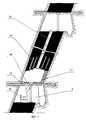
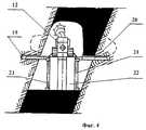
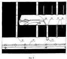
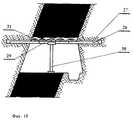
На фиг. 1 показана схема вскрытия и подготовки выемочного поля; на фиг. 2 - разрез выемочного поля вкрест простирания пласта; на фиг. 3 - схема отработки первого слоя; на фиг. 4 - схема сооружения подмостей; на фиг. 5 - схема подрубки боковых пород; на фиг. 6 - положение комбайна на подмостях перед разворотом; на фиг. 7 - положение в слое перед подачей гидрозакладки; на фиг. 8 - схема отработки слоя с оставлением целика; на фиг. 9 - схема разработки (текущее положение); на фиг. 10 - поперечное сечение конвейерного штрека. In FIG. 1 shows a scheme for opening and preparing a mining field; in FIG. 2 - section of the excavation field across the strike of the formation; in FIG. 3 - scheme of working out the first layer; in FIG. 4 is a diagram of the construction of scaffolding; in FIG. 5 is a schematic diagram of the sidecut formation; in FIG. 6 - position of the harvester on the scaffolds before a turn; in FIG. 7 - position in the layer before applying the hydraulic filling; in FIG. 8 is a diagram of working out a layer with leaving a pillar; in FIG. 9 - development scheme (current position); in FIG. 10 is a cross section of a conveyor drift.
Способ может быть реализован следующим образом. Мощный крутой пласт угля вскрывают вентиляционным 1 и транспортным 2 квершлагами. Выемочное поле подготавливают проведением вентиляционного 3 и конвейерного 4 штреков, которые сбивают двумя скатами 5 и 6, деля таким образом выемочное поле на три зоны: зону 7 - выемки и две монтажно-маневровые зоны 8 и 9. С конвейерного штрека 4 на всю высоту выемочного поля на равном расстоянии друг от друга в средней части пласта бурят скважины 10, которые обсаживают участками труб 11, длина которых принимается равной наклонной высоте горизонтального слоя. The method can be implemented as follows. A powerful steep coal seam is opened with ventilation 1 and
Первый слой вынимают, например, проходческим комбайном 12 типа 4ПУ, в нижней части выемочного поля, непосредственно примыкающей к конвейерному штреку 4. По мере выемки слоя в промежутках между скважинами 10 сооружают углеспуски 13. Отбитый уголь по телескопическим желобам 14 и углеспускам 13 поступает на конвейерный штрек 4 и конвейером 15 транспортируется за пределы выемочного поля. Потолочине слоя придают форму арочного свода для большей полноты заполнения выработанного пространства гидрозакладкой. Поддержание выработанного пространства осуществляют анкерным креплением 16 потолочины равномерно по всей длине слоя. При этом используется анкер с большим сопротивлением на растяжение и малым - на срез, например, полимерный. The first layer is taken out, for example, by a
По окончании выемки первого слоя в зоне выемки 7 его выработанное пространство готовят к заполнению закладочным материалом. Для этого часть пространства, прилегающую к почве пласта и конвейерному штреку, заполняют фильтрующим материалом, задерживающим закладочный материал, но хорошо пропускающим воду, сооружая тем самым дрену 17. Почву слоя изолируют от конвейерного штрека 4 герметичным материалом 18, например, отрезками отслужившего вентиляционного рукава. Ко всем углеспускам 13 присоединяют по одному участку труб 11, демонтированным из скважин 10. Выемочную зону изолируют перемычками (не показано) в районе скатов 5 и 6, после чего подают закладочный материал по скважинам 10. При этом через дрену 17 вода уходит на штрек 4 и далее по водоотводной канавке в зумпф, а твердая фракция закладки остается в выработанном пространстве слоя, заполняя его на всю мощность. At the end of the excavation of the first layer in the
В это же время в монтажно-маневровой зоне 9 ведут работы по развороту комбайна 12 и переводу его на следующий (второй) слой. При этом вынимают первый слой как описано выше, но, дойдя до границы выемочного поля, комбайн 12 задним ходом сдают назад к скату 6, перед ним монтируют подмости. Для этого в кровлю и почву пласта на уровне потолочины бурят неглубокие скважины 19 и вставляют в них одним концом балки 20, противоположные концы которых скрепляют болтовыми соединениями. Под балки устанавливают жесткие металлические опоры 21. Затем сооружают заезд 22, по которому комбайн 12 прямым ходом забирается на подмости, разрушая при этом верхнюю пачку угля и формируя выработанное пространство следующего слоя. Передвигая комбайн 12 по подмостям вперед - назад, на подмостях сооружают настил 23. После заезда комбайна 12 на настил 23 его исполнительным органом разрушают боковые породы по обе стороны от его корпуса при необходимом продвижении вперед, формируя пространство для разворота. Затем разворачивают комбайн 12 на 180o и отключают от системы электроснабжения. После возведения необходимых перемычек и демонтажа заезда 22 в зону 9 подают гидрозакладку, заполняя пространство зоны 9 до уровня настила 23.At the same time, in the mounting and shunting
После схода воды и отхода комбайна с подмостей извлекают балки 20 и опоры 21 для повторного использования. After the descent of water and the withdrawal of the harvester from the scaffolds, the
Следующий слой вынимают аналогично описанному, но теперь комбайн дополнительно разрушает полимерные анкера 16, установленные при отработке предыдущего слоя. При этом проветривание слоя осуществляют подачей свежей воздушной струи от ската 5 или 6 - выработанное пространство слоя - скважины 10 - вентиляционный штрек 3. The next layer is removed as described, but now the combine further destroys the
После отработки второго слоя в зоне 7 комбайн 12 переходи в зону 8, в которой первый слой еще не отработан. Здесь работа по выемке организуется следующим образом. Со штрека 4 в промежутках между скважинами 10 бурят скважины 24 на высоту немногим больше наклонной высоты первого слоя, ориентируя их по линии восстания, обсаживают их участками труб 11 и сооружают углеспуски 13. По мере подвигания комбайна участки скважин 10, оказавшиеся ниже второго слоя, заполняют фильтрующим материалом, сооружая дрены 25, и оставляют целик 26. After mining the second layer in
За счет использования более дешевой закладки резко снижается себестоимость добычи угля из мощного крутого пласта; за счет использования углеспусков и желобов снижаются затраты на монжат-демонтаж транспортного средства в пределах слоя. Through the use of cheaper bookmarks, the cost of coal mining from a powerful steep bed is sharply reduced; due to the use of coal gutters and gutters, the costs of the monzhat-dismantling of the vehicle within the layer are reduced.
Проведение слоевого штрека может быть осуществлено следующим образом. По мере подвигания комбайна осуществляют бурение неглубоких скважин 27 попарно в кровлю и почву пласта в верхней части выработки, ориентируя их по горизонтальной оси, перпендикулярной оси проводимой выработки. В каждую скважину вставляют одним концом балку 28, например, из двутавра, другой конец которой скрепляют с одноименным концом балки, вставленной в скважину напротив, например, при помощи накладок 29 и болтовых соединений. Под каждую пару скрепленных балок устанавливают металлическую опору 30. Соседние пары балок, при необходимости, связывают растяжками. Кровлю выработки перетягивают деревянной затяжкой 31. Conducting a lay drift can be carried out as follows. As the combine moves, shallow wells are drilled 27 in pairs in the roof and in the soil of the formation in the upper part of the mine, orienting them along the horizontal axis perpendicular to the axis of the mine. A
Предполагается, что описанная крепь будет значительно более устойчивой и обладать значительно большей несущей способностью. За счет использования более жесткого металлопроката в качестве балок, более частой их установки и перетяжки кровли выработки деревянной затяжкой возможна отработка первого слоя описанного способа разработки без оставления целика над слоевым штреком. It is assumed that the described lining will be much more stable and have significantly greater bearing capacity. Due to the use of stiffer metal rolling as beams, their more frequent installation and hauling of the roof of the roof with a wooden puff, it is possible to work out the first layer of the described development method without leaving the pillar above the layer drift.
Таким образом, использование способа разработки и способа проведения слоевой выработки позволит снизить затраты на добычу угля из мощного крутого угольного пласта, т.е. повысить эффективность производства. Thus, the use of the development method and the method for conducting the layer production will reduce the cost of coal mining from a powerful steep coal seam, i.e. increase production efficiency.
Источники информации, принятые во внимание при составлении заявки:
1. Авторское свидетельство СССР N 981608, 1982.Sources of information taken into account when preparing the application:
1. USSR author's certificate N 981608, 1982.
2. Авторское свидетельство СССР N 920214, 1982. 2. Copyright certificate of the USSR N 920214, 1982.
3. Гелескул М. Н. , Усан-Подгорнов Б.М., Кушнарев А.А. Справочник проходчика. - М.: Недра, 1979, с. 195. 3. Geleskul M. N., Usan-Podgornov B. M., Kushnarev A. A. Guide to the tuner. - M .: Nedra, 1979, p. 195.
Claims (3)
Translated fromRussianPriority Applications (1)
| Application Number | Priority Date | Filing Date | Title |
|---|---|---|---|
| RU97105521ARU2122634C1 (en) | 1997-04-03 | 1997-04-03 | Method of mining thick steeply dipping coal seam by horizontal layers |
Applications Claiming Priority (1)
| Application Number | Priority Date | Filing Date | Title |
|---|---|---|---|
| RU97105521ARU2122634C1 (en) | 1997-04-03 | 1997-04-03 | Method of mining thick steeply dipping coal seam by horizontal layers |
Publications (2)
| Publication Number | Publication Date |
|---|---|
| RU2122634C1true RU2122634C1 (en) | 1998-11-27 |
| RU97105521A RU97105521A (en) | 1999-04-27 |
Family
ID=20191682
Family Applications (1)
| Application Number | Title | Priority Date | Filing Date |
|---|---|---|---|
| RU97105521ARU2122634C1 (en) | 1997-04-03 | 1997-04-03 | Method of mining thick steeply dipping coal seam by horizontal layers |
Country Status (1)
| Country | Link |
|---|---|
| RU (1) | RU2122634C1 (en) |
Cited By (5)
| Publication number | Priority date | Publication date | Assignee | Title |
|---|---|---|---|---|
| RU2246619C1 (en)* | 2003-12-10 | 2005-02-20 | Государственное образовательное учреждение высшего профессионального образования Санкт-Петербургский государственный горный институт им. Г.В. Плеханова (технический университет) | Method for constructing artificial supports during extraction of steep beds |
| RU2254466C1 (en)* | 2004-04-12 | 2005-06-20 | Государственное образовательное учреждение высшего профессионального образования Санкт-Петербургский государственный горный институт им. Г.В. Плеханова (технический университет) | Fire-hazardous beds development method |
| WO2019100906A1 (en)* | 2017-11-22 | 2019-05-31 | 中国矿业大学 | Downward filling mining method for extra-thick coal seam |
| CN113153301A (en)* | 2021-06-01 | 2021-07-23 | 闫少宏 | Horizontal sectional mechanized top coal caving mining method for steep coal seam |
| CN114704256A (en)* | 2022-03-28 | 2022-07-05 | 长沙矿山研究院有限责任公司 | A non-explosive mechanical rock-breaking circulation approach filling mining method |
- 1997
- 1997-04-03RURU97105521Apatent/RU2122634C1/enactive
Non-Patent Citations (1)
| Title |
|---|
| Гелескул М.Н. и др. Справочник проходчика. - М.: Недра, 1979, с.195.* |
Cited By (5)
| Publication number | Priority date | Publication date | Assignee | Title |
|---|---|---|---|---|
| RU2246619C1 (en)* | 2003-12-10 | 2005-02-20 | Государственное образовательное учреждение высшего профессионального образования Санкт-Петербургский государственный горный институт им. Г.В. Плеханова (технический университет) | Method for constructing artificial supports during extraction of steep beds |
| RU2254466C1 (en)* | 2004-04-12 | 2005-06-20 | Государственное образовательное учреждение высшего профессионального образования Санкт-Петербургский государственный горный институт им. Г.В. Плеханова (технический университет) | Fire-hazardous beds development method |
| WO2019100906A1 (en)* | 2017-11-22 | 2019-05-31 | 中国矿业大学 | Downward filling mining method for extra-thick coal seam |
| CN113153301A (en)* | 2021-06-01 | 2021-07-23 | 闫少宏 | Horizontal sectional mechanized top coal caving mining method for steep coal seam |
| CN114704256A (en)* | 2022-03-28 | 2022-07-05 | 长沙矿山研究院有限责任公司 | A non-explosive mechanical rock-breaking circulation approach filling mining method |
Similar Documents
| Publication | Publication Date | Title |
|---|---|---|
| CN104806244B (en) | Filling mining method for slant middle-thick ore body | |
| CN111594168B (en) | A kind of mining method with limited subsidence supported by pseudo-goaf with rock gangue forming | |
| BR112012021093B1 (en) | method for block abatement mining | |
| CN105804748B (en) | A kind of method of block mining Wall ore under open air transport system | |
| RU2344291C2 (en) | System of deposit development | |
| CN114592909A (en) | Downward layered access filling mining method for extremely-broken thick and large ore body | |
| CN118065901A (en) | Combined mining method and system for extremely broken medium-thick ore bodies | |
| RU2122634C1 (en) | Method of mining thick steeply dipping coal seam by horizontal layers | |
| RU2354829C1 (en) | Method of thick flat coal bed development | |
| RU2168629C1 (en) | Method of mining of thick flat coal bed | |
| RU2155868C2 (en) | Method of rise rill cut mining with filling of pipe-like kimberlite deposits by powder mining complex | |
| RU2233983C1 (en) | Method for extracting massive sloping coal bed by horizontal descending layers with full filling of extracted space | |
| RU97105521A (en) | METHOD FOR DEVELOPING A POWERFUL STEEL COAL COAL LAYER BY HORIZONTAL LAYERS | |
| RU2116447C1 (en) | Method and powered complex for mining kimberlite pipes | |
| SU1795100A1 (en) | Method for mining thick steeply dipping coal seams | |
| RU2175062C2 (en) | Method of advanced anchoring of roof of edge part of seam of stope | |
| RU2155867C2 (en) | Method of downward working of kimberlite pipe by powered mining complex and design of flexible guard roofing | |
| RU2094612C1 (en) | Method for opening steep thin ore deposits | |
| RU2151294C1 (en) | Method of horizontal slicing of thick steep coal seam | |
| RU2011823C1 (en) | Method for mining of thick steep fire-hazardous coal seams | |
| SU1728488A1 (en) | Method of mining coal seams | |
| RU2200840C2 (en) | Process of development of gently dipping and inclined coal formations with use of cleaning powered complexes | |
| RU2231642C1 (en) | Method of barring and development of elongated in width and gradient coal fields with flat dipping and inclined beds of big thickness | |
| RU2471990C1 (en) | Method to mine sloping and inclined coal beds of average capacity | |
| RU2344292C1 (en) | Method of development of thick flat-lying coal bed on clots of irregular shape |