RU2120183C1 - Communication system and method for dynamic optimization of its characteristics - Google Patents
Communication system and method for dynamic optimization of its characteristicsDownload PDFInfo
- Publication number
- RU2120183C1 RU2120183C1RU95105526ARU95105526ARU2120183C1RU 2120183 C1RU2120183 C1RU 2120183C1RU 95105526 ARU95105526 ARU 95105526ARU 95105526 ARU95105526 ARU 95105526ARU 2120183 C1RU2120183 C1RU 2120183C1
- Authority
- RU
- Russia
- Prior art keywords
- attenuation
- signal
- input stage
- control means
- receiver
- Prior art date
Links
Images


Classifications
- H—ELECTRICITY
- H04—ELECTRIC COMMUNICATION TECHNIQUE
- H04B—TRANSMISSION
- H04B7/00—Radio transmission systems, i.e. using radiation field
- H04B7/005—Control of transmission; Equalising
- H—ELECTRICITY
- H04—ELECTRIC COMMUNICATION TECHNIQUE
- H04W—WIRELESS COMMUNICATION NETWORKS
- H04W52/00—Power management, e.g. Transmission Power Control [TPC] or power classes
- H04W52/04—Transmission power control [TPC]
- H04W52/18—TPC being performed according to specific parameters
- H04W52/22—TPC being performed according to specific parameters taking into account previous information or commands
- H04W52/228—TPC being performed according to specific parameters taking into account previous information or commands using past power values or information
- H—ELECTRICITY
- H04—ELECTRIC COMMUNICATION TECHNIQUE
- H04W—WIRELESS COMMUNICATION NETWORKS
- H04W52/00—Power management, e.g. Transmission Power Control [TPC] or power classes
- H04W52/04—Transmission power control [TPC]
- H04W52/18—TPC being performed according to specific parameters
- H04W52/20—TPC being performed according to specific parameters using error rate
Landscapes
- Engineering & Computer Science (AREA)
- Computer Networks & Wireless Communication (AREA)
- Signal Processing (AREA)
- Transmitters (AREA)
- Mobile Radio Communication Systems (AREA)
- Transceivers (AREA)
- Input Circuits Of Receivers And Coupling Of Receivers And Audio Equipment (AREA)
- Cable Transmission Systems, Equalization Of Radio And Reduction Of Echo (AREA)
- Reduction Or Emphasis Of Bandwidth Of Signals (AREA)
- Circuits Of Receivers In General (AREA)
Abstract
Description
Translated fromRussianИзобретение относится к системам связи, содержащим передатчики и приемники, а более конкретно к системе связи, которая оптимизирует эксплуатационные характеристики путем динамического регулирования мощности передатчика и ослабления в приемнике. The invention relates to communication systems containing transmitters and receivers, and more particularly to a communication system that optimizes performance by dynamically controlling transmitter power and attenuation in the receiver.
В типовой системе связи, например в сотовой телефонной системе, приемник предназначен для работы с сигналами в определенном диапазоне их интенсивностей. Этот диапазон интенсивностей называется динамическим диапазоном приемника. Наименьший сигнал, который может быть принят приемником, определяет чувствительность приемника, а сигнал с наивысшей интенсивностью определяет предел запирания (насыщения). In a typical communication system, for example in a cellular telephone system, the receiver is designed to work with signals in a certain range of their intensities. This range of intensities is called the dynamic range of the receiver. The smallest signal that can be received by the receiver determines the sensitivity of the receiver, and the signal with the highest intensity determines the limit of blocking (saturation).
В сотовой телефонной системе расстояние между базовой станцией и мобильной (подвижной) станцией изменяется при передвижении мобильной станции в пределах ячейки сотовой структуры. Вследствие этого в больших ячейках изменения интенсивности сигнала могут быть очень велики. Иногда эти изменения становятся столь значительными, что они уже не могут быть скомпенсированы изменением мощности передатчика мобильной станции. В таких ячейках весьма целесообразным было бы изменение или смещение динамического диапазона, т.е. диапазона интенсивностей сигнала, определяемого наибольшим и наименьшим принимаемым сигналом, в соответствии с расстоянием между базовой и мобильной станциями. In a cellular telephone system, the distance between the base station and the mobile (mobile) station changes as the mobile station moves within the cell of the cellular structure. As a result, in large cells, changes in signal intensity can be very large. Sometimes these changes become so significant that they can no longer be compensated by a change in the transmitter power of the mobile station. In such cells, a change or shift of the dynamic range, i.e. the range of signal intensities determined by the largest and smallest received signal, in accordance with the distance between the base and mobile stations.
Динамический диапазон приемника может быть смещен (перенесен) путем введения аттенюатора между антенной и приемником. При увеличении ослабления увеличиваются как наименьший, так и набольший допустимые уровни принимаемых сигналов. Аналогично при уменьшении ослабления динамический диапазон смещается в сторону более низких величин интенсивностей сигналов. Это воздействие ослабления сигналов на динамический диапазон иллюстрируется на фиг. 1. Когда ослабление установлено на 0 дБ, динамический диапазон приемника 101 определяется чувствительностью 102 и пределом насыщения 103. The dynamic range of the receiver can be shifted (transferred) by introducing an attenuator between the antenna and the receiver. With an increase in attenuation, both the smallest and the largest allowable levels of received signals increase. Similarly, when attenuation is reduced, the dynamic range shifts toward lower signal intensities. This effect of signal attenuation on dynamic range is illustrated in FIG. 1. When attenuation is set to 0 dB, the dynamic range of receiver 101 is determined by sensitivity 102 and saturation limit 103.
Если ослабление увеличивают на 3 дБ, динамический диапазон сдвигается в новую область 104, определяемую чувствительностью 105 и пределом насыщения 106, которые оба в основном на 3 дБ выше, чем соответствующие чувствительность 102 и предел насыщения 103 в случае ослабления, равного 0 дБ. Аналогично, если ослабление установлено на 6 дБ, чувствительность 108 и предел насыщения 109 снова увеличиваются, образуя новый динамический диапазон приемника 107. If the attenuation is increased by 3 dB, the dynamic range shifts to a new region 104, determined by a sensitivity of 105 and a saturation limit of 106, which are both basically 3 dB higher than the corresponding sensitivity of 102 and a saturation limit of 103 in the case of attenuation of 0 dB. Similarly, if attenuation is set to 6 dB, sensitivity 108 and saturation limit 109 increase again, forming a new dynamic range for receiver 107.
В малых по размеру ячейках расстояние между мобильной станцией и базовой станцией может быть очень малым. Это может привести к помехам в приемной полосе частот, если имеются большие ячейки, охватывающие то же пространство, что и малая ячейка. Такие большие ячейки могут относиться к той же сети, что и малая ячейка, но может также быть и частью другой сети, работающей в той же или в соседней полосе частот. Мерой упомянутых помех может быть частота ошибок по битам в цифровых системах связи. В аналоговых системах могут использоваться другие критерии оценки качества сигналов, например общее искажение модулированного пилот-сигнала (контрольного сигнала). In small cells, the distance between the mobile station and the base station can be very small. This can lead to interference in the receiving frequency band if there are large cells covering the same space as the small cell. Such large cells may belong to the same network as the small cell, but may also be part of another network operating in the same or adjacent frequency band. A measure of the mentioned interference may be the bit error rate in digital communication systems. In analog systems, other criteria for evaluating signal quality may be used, for example, the total distortion of the modulated pilot signal (pilot).
Описанная ситуация иллюстрируется на фиг. 2, где показана базовая станция В 201, расположенная в ячейке 202, и базовая станция А 203 в ячейке 204. Можно видеть, что ячейка 204 по размеру меньше ячейки 202 и определяет географическую область внутри или вблизи ячейки 202. Вследствие такого различия размеров ячеек одно относительно другой ячейку 202 можно назвать "макроячейкой", а ячейку 204 - "микроячейкой". Когда мобильная станция 205, входящая в "макроячейку" 202, перемещается вблизи базовой станции А 203, в ее приемнике могут возникать помехи от воздействия мобильной станции В 205. Такая ситуация может иметь место даже в том случае, если полоса радиочастот, используемых базовой станцией А 203, значительно удалена из полосы частот базовой станции В 201 и мобильной станции В 205. The described situation is illustrated in FIG. 2, where the
Если базовая станция А 203 снабжена динамически регулируемым аттенюатором, установленным между антенной и приемником, как это указывалось выше, то ослабление может быть увеличено до уровня, при котором помехи в приемнике окажутся на допустимо низком уровне. Именно этим объясняется эффект уменьшения помех в приемной полосе частот с изменением величины ослабления, вносимого аттенюатором. Однако при этом и полезный (рабочий) сигнал, передаваемый мобильной станцией А 206 на базовую станцию А 203, также ослабляется на величину ослабления аттенюатора. Это может привести к тому, что сигнал от мобильной станции А 206 будет иметь уровень недопустимо малый для приема его базовой станцией А 203. If the base station A 203 is equipped with a dynamically adjustable attenuator installed between the antenna and the receiver, as indicated above, the attenuation can be increased to a level at which the interference in the receiver will be at an acceptably low level. This explains the effect of reducing interference in the receiving frequency band with a change in the attenuation introduced by the attenuator. However, at the same time, the useful (working) signal transmitted by the mobile station A 206 to the base station A 203 is also attenuated by the attenuation attenuation value. This can lead to the fact that the signal from the mobile station A 206 will have an unacceptably low level for reception by the base station A 203.
Сущность изобретения
Изложенные выше и другие задачи решаются в настоящем изобретении путем динамического управления как ослаблением в приемнике базовой станции А 203, так и мощностью передатчика мобильной станции А 206.SUMMARY OF THE INVENTION
The above and other problems are solved in the present invention by dynamically controlling both the attenuation in the receiver of the
Согласно одному из аспектов изобретения, предлагается приемник, предназначенный для приема сигналов связи от передатчика, которые затем ослабляются в приемнике. Далее производится измерение уровня принятого сигнала. Измеренное значение мощности сигнала подается на средство, предназначенное для управления ослаблением, и на средство управления передаваемой мощностью. Средство управления ослаблением динамически управляет степенью ослабления принимаемого сигнала. Средство управления мощностью передачи вырабатывает сигнал управления мощностью, который подлежит пересылке к передатчику. Передатчик использует принятый им сигнал управления мощностью для регулирования уровня мощности сигналов связи, передаваемых им к приемнику. Как средство управления ослаблением, так и средство управления параметрами передатчика управляют соответственно ослаблением приемника и уровнем передаваемой мощности с тем, чтобы оптимизировать характеристики системы. According to one aspect of the invention, there is provided a receiver for receiving communication signals from a transmitter, which are then attenuated at the receiver. Next, the level of the received signal is measured. The measured value of the signal power is supplied to the means for controlling attenuation, and to the means for controlling the transmitted power. The attenuation control means dynamically controls the degree of attenuation of the received signal. The transmit power control means generates a power control signal, which is to be forwarded to the transmitter. The transmitter uses its received power control signal to adjust the power level of the communication signals transmitted by it to the receiver. Both the attenuation control means and the transmitter parameter control means respectively control the attenuation of the receiver and the level of transmitted power in order to optimize system performance.
В соответствии с другим аспектом настоящего изобретения ослабление в приемнике и уровень мощности передатчика регулируются так, чтобы ослабленный сигнал не выходил за пределы динамического диапазона приемника. Это может быть полезным, например, при конструировании не очень дорогих приемников с уменьшенным динамическим диапазоном, что компенсируется путем соответствующей регулировки ослабления приемника и уровня мощности в режиме передачи. In accordance with another aspect of the present invention, the attenuation at the receiver and the power level of the transmitter are adjusted so that the attenuated signal does not go beyond the dynamic range of the receiver. This can be useful, for example, when designing not very expensive receivers with a reduced dynamic range, which is compensated by appropriate adjustment of the attenuation of the receiver and the power level in the transmission mode.
В соответствии еще с одним аспектом настоящего изобретения ослабление в приемнике регулируется таким образом, что чувствительность приемника остается на относительно высоком уровне по сравнению с уровнем помехового сигнала, причем в то же время уровень мощности передатчика регулируется так, чтобы сигнал связи, прошедший через аттенюатор, оставался в пределах динамического диапазона приемника. In accordance with another aspect of the present invention, the attenuation in the receiver is controlled so that the sensitivity of the receiver remains relatively high compared to the level of the interfering signal, while at the same time, the power level of the transmitter is adjusted so that the communication signal passed through the attenuator remains within the dynamic range of the receiver.
Еще одной особенностью настоящего изобретения является возможность совмещения аттенюатора с антенной, имеющей динамически регулируемое усиление (коэффициент передачи). Another feature of the present invention is the ability to combine the attenuator with an antenna having a dynamically adjustable gain (gain).
И еще один аспект настоящего изобретения заключается в том, что динамическая регулировка ослабления в приемнике и уровня мощности в режиме передачи используется в системе, в которой множество приемников подключаются к общей антенне через многоканальный разветвитель. В одном из вариантов реализации между общей антенной и многоканальным разветвителем установлен общий аттенюатор. В другом варианте реализации каждый приемник имеет средства ослабления принимаемых им связных сигналов. And another aspect of the present invention is that dynamically adjusting receiver attenuation and transmit power level is used in a system in which multiple receivers are connected to a common antenna through a multi-channel splitter. In one embodiment, a common attenuator is installed between a common antenna and a multi-channel splitter. In another embodiment, each receiver has means for attenuating the received signals it receives.
Краткое описание чертежей
Перечисленные и другие аспекты настоящего изобретения будут пояснены последующим подробным описанием со ссылками на прилагаемые чертежи, на которых показано следующее: на фиг. 1 - график, показывающий зависимость динамического диапазона приемника от величины ослабления сигналов; на фиг. 2 - иллюстрация ситуации, когда малая ячейка сети с мобильной станцией связи по крайней мере частично расположена внутри большой ячейки сети связи; на фиг. 3 - блок-схема устройства согласно настоящему изобретению для динамического регулирования ослабления в приемнике и мощности передатчика; на фиг. 4 - блок-схема устройства с несколькими приемниками, подключенными к одной антенне в соответствии с другим вариантом реализации изобретения; на фиг. 5 - блок-схема еще одного варианта реализации изобретения, где используется раздельное ослабление в системе со множеством приемников, подключенных к общей антенне через многоканальный разветвитель; на фиг. 6 - блок-схема альтернативного варианта реализации изобретения, в котором антенна и перестраиваемой аттенюатор объединены в общий блок.Brief Description of the Drawings
The listed and other aspects of the present invention will be explained by the following detailed description with reference to the accompanying drawings, in which the following is shown: in FIG. 1 is a graph showing the dependence of the dynamic range of the receiver on the amount of attenuation of signals; in FIG. 2 is an illustration of a situation where a small cell of a network with a mobile communication station is at least partially located inside a large cell of a communication network; in FIG. 3 is a block diagram of a device according to the present invention for dynamically controlling attenuation in a receiver and transmitter power; in FIG. 4 is a block diagram of a device with multiple receivers connected to one antenna in accordance with another embodiment of the invention; in FIG. 5 is a block diagram of another embodiment of the invention where separate attenuation is used in a system with multiple receivers connected to a common antenna through a multi-channel splitter; in FIG. 6 is a block diagram of an alternative embodiment of the invention, in which the antenna and tunable attenuator are combined into a common unit.
Подробное описание изобретения
На фиг. 3 показана мобильная система связи, включающая настоящее изобретение. Блоки справа от штрих-пунктирной линии 301 относятся к мобильной станции, а блоки слева от линии 301 - к базовой станции.DETAILED DESCRIPTION OF THE INVENTION
In FIG. 3 shows a mobile communication system including the present invention. The blocks to the right of dash-
Сигналы, принимаемые базовой станцией через антенну (не показана), являются входными сигналами для динамически регулируемого аттенюатора 302. С выхода аттенюатора 302 сигнал подается на вход схемы измерения интенсивности (мощности) сигнала 303, а выход этой схемы 303 соединен со входами схемы управления ослаблением 304 и схемы управления мощностью 305 мобильной станции. Схема управления ослаблением 304 соединена с аттенюатором 302 для управления степенью ослабления сигнала. Схема управления мощностью 305 мобильной станции использует выходной сигнал схемы измерения 305 интенсивности сигнала для формирования сигнала, который посылается на схему контроля мощности 306 мобильной станции, где этот сигнал регулирует уровень мощности, излучаемой передатчиком мобильной станции. В одном из предпочтительных вариантов реализации настоящего изобретения функции измерения интенсивности сигнала и регулирования мощности реализованы в соответствии со стандартами, положенными в основу Глобальной Системы Мобильной связи (GSM) Европейского Института Стандартов по Связи (ETSI), которая используется в данном случае в качестве ссылочного материала. В частности, в GSM - рекомендациях 05.08 в разделах 8.1.2. и 8.1.3 описаны процедуры измерений интенсивности сигналов. Там же в разделах 3.2 - 4.7 и в разделе 4.1 GSM - рекомендаций 05.05 описывается управление мощностью на радиочастотах. Ниже более подробно описываются управляющие функции схемы управления ослаблением 304 и схемы управления мощностью 305 мобильной станции. The signals received by the base station through an antenna (not shown) are input to the dynamically controlled
Одной из функций системы динамического управления, показанной на фиг. 3, является компенсация изменений интенсивности сигнала, принимаемого базовой станцией В 201 (см. фиг. 2), имеющих место при перемещении мобильной станции В 205 в пределах большой ячейки сети 202. Если мощность излучения мобильной станции В 205 постоянна, то интенсивность сигнала, принимаемого базовой станцией В 201, уменьшается с увеличением расстояния между мобильной станцией В 205 и базовой станцией В 201. И наоборот, если мобильная станция В 205 приближается к базовой станции В 201, интенсивность принимаемого сигнала увеличивается, но опять же при соблюдении того условия, что уровень мощности излучения мобильной станции поддерживается постоянным. One of the functions of the dynamic control system shown in FIG. 3 is compensation for changes in the intensity of the signal received by the base station B 201 (see FIG. 2) that occur when the
В настоящем изобретении также эффекты компенсируются следующим образом. Когда мобильная станция В 205 находится вблизи границы ячейки 202, схема управления мощностью 305 мобильной станции, обнаружив уменьшение интенсивности принимаемого сигнала, передает сигнал, предписывающий мобильной станции В 205 вести передачу при более высоком уровне мощности. Вследствие больших потерь сигнала, которые имеют место при его прохождении расстояния между станциями, принятый сигнал может иметь на базовой станции В 201 весьма малую интенсивность и может быть близок к порогу чувствительности приемника. In the present invention, effects are also compensated as follows. When the
Когда мобильная станция В 205 движется по направлению к базовой станции В 201, то мощность принимаемого этой базовой станцией сигнал увеличивается. Это обнаруживается схемой управления мощностью передачи 305 мобильной станции, которая реагирует путем посылки сигнала к мобильной станции В 205, вызывающего уменьшение передаваемой мощности до уровня, при котором принимаемый сигнал находится в пределах динамического диапазона приемника. По мере приближения мобильной станции В 205 к базовой станции В 201 в некоторой токе мобильная станция В 205 начнет работать при минимальном возможном уровне излучаемой мощности. А затем при продолжающемся сближении этих двух станций мощность принимаемого сигнала начнет возрастать и, спустя некоторое время, станет недопустимо большой. Иначе говоря, несмотря на то, что мобильная станция В 205 ведет передачу при минимально возможном уровне мощности, ее близость к базовой станции В 201 приводит к превышению интенсивности принимаемого сигнала над уровнем насыщения приемника. When the
Эта проблема решается в настоящем изобретении с помощью схемы управления ослаблением 304, которая обнаруживает принимаемый сигнал с недопустимо высокой интенсивностью и выдает на аттенюатор 302 команду увеличить величину вносимого ослабления. В результате этого верхний предел допустимого уровня сигнала (т. е. предел насыщения) увеличивается и проблема, связанная с высоким уровнем принимаемого сигнала, решается. This problem is solved in the present invention using the
Другая проблема, которую решает настоящее изобретение, относится к описанной выше ситуации, когда малая ячейка 204 располагается внутри или вблизи большой ячейки 202. При этом, как уже упоминалось ранее, в приемнике базовой станции А 203 помехи, вызываемые мобильной станцией В 205, которая пытается вести передачу, предназначенную для базовой станции В 201, могут быть весьма мощными, по сравнению с полезным сигналом, излучаемым мобильной станцией А 206. Another problem that the present invention solves relates to the situation described above when the
В соответствии с настоящим изобретением схема управления мощностью 305 мобильной станции обнаруживает высокий уровень помех, проявляющихся в цифровых системах связи, например, в виде увеличения частоты ошибок по битам, после чего эта схема задает следующий порядок работы. Схема управления ослаблением 304 дает команду аттенюатору 302 увеличивать степень ослабления до тех пор, пока помехи 110 не уменьшаются (см. фиг. 1) в достаточной степени, возможно даже до уровня ниже порога чувствительности 105 приемника. Однако в результате и полезный сигнал несущей частоты также подвергается ослаблению. Для его компенсации схема управления мощностью 305 мобильной станции посылает сигнал на схему управления мощностью 306 мобильной станции А 206, предписывающий увеличение мощности передачи до тех пор, пока интенсивность принимаемого приемником сигнала несущей частота III (см. фиг. 1) не превысит порог чувствительности 105 приемника. Таким образом интенсивность полезного сигнала поддерживается постоянной на уровне выше порога чувствительности при одновременном подавлении помех. In accordance with the present invention, the
Специалистам в данной области техники должно быть понято, что описанный выше порядок работы может быть несколько иным, а именно от схемы управления мощностью 305 мобильной станции может быть послан сигнал к мобильной станции А 206 с командой увеличить уровень мощности передатчика с тем, чтобы соответственно увеличилась мощность принимаемого базовой станцией сигнала, и уменьшить в результате этого частоту ошибок по битам. После этого схема управления степенью ослабления 304 могла бы в ответ на это увеличить ослабление принимаемого сигнала с тем, чтобы снизить его интенсивность до требуемого уровня. It should be understood by those skilled in the art that the operating procedure described above may be slightly different, namely, a signal can be sent from the mobile
Особенность одного из вариантов реализации настоящего изобретения состоит в том, что динамическое управление ослаблением, осуществляемое схемой 304, совмещается с процессом управления мощностью мобильной станции в режиме передачи, что является функцией схемы 305, при этом мощность передатчика определяют на основе анализа качества принимаемого сигнала. Благодаря такому совмещению этих двух функций возникает возможность предотвратить ненужное ослабление полезного сигнала, когда помехи имеют низкий уровень. Это дает то преимущество, что мощность излучения мобильной станции поддерживается на минимальном уровне, а это весьма важно во многих случаях использования мобильной связи. В одном из предпочтительных вариантов реализации настоящего изобретения процесс управления мощностью мобильной станции, при котором качество принимаемого сигнала используется для определения мощности в режиме передачи, осуществляется так, как это описано в совместно поданной заявке на патент США, озаглавленной "Способ и устройство для регулирования мощности передачи в радиосистеме", авторы Альмгрен и др., поданной 14 мая 1993 г., принадлежащей тому же заявителю, что и в настоящем изобретении. A feature of one embodiment of the present invention is that the dynamic attenuation control performed by the
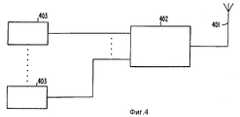
Базовые станции часто содержат несколько приемников, подключенных к одной и той же приемной антенне. В таких случаях средства ослабления сигналов должны быть надлежащим образом разделены. Ниже описывается один из вариантов реализации настоящего изобретения со ссылкой на фиг. 4 и 5, имеющий упомянутую особенность. Base stations often contain multiple receivers connected to the same receive antenna. In such cases, signal attenuation means must be appropriately separated. One embodiment of the present invention is described below with reference to FIG. 4 and 5 having said feature.
На фиг. 4 показаны несколько приемников 403, подключенных к одной антенне 401 через приемник - многоканальный разветвитель 402, который выполнен в виде широкополосного усилителя, принимающего широкополосный сигнал и имеющего множество узкополосных сигнальных выходов. В каждом из приемников 403 может быть реализовано настоящее изобретение в объеме, раскрытом выше со ссылкой на фиг. 3. Однако сам приемник-разветвитель 402 может оказаться в состоянии насыщения (запирания), обусловленном сильными сигналами, поступающими на его вход от антенны 401. В этом случае вполне очевидно, что любое ослабление в отдельных приемниках 403 не позволяет избежать такой перегрузки. Для устранения этой проблемы приемник-разветвитель 402 должен проектироваться на более высокий предел насыщения, чем каждый из приемников 403. In FIG. 4 shows
Другое решение проблемы насыщения приемника-разветвителя 402 показано на фиг. 5. Здесь средства ослабления разделены с тем, чтобы можно было выбрать оптимальное ослабление в тракте сигнала как до, так и после приемника-разветвителя 402. Another solution to the saturation problem of the
На фиг. 5 показан один из N приемников 503. Хотя последующее описание относится только к одному такому приемнику, вполне понятно, что оно применимо и к любому из N приемников 503. Каждый из приемников 503 содержит схему управления, описанную выше со ссылкой на фиг. 3. Кроме того, выход схемы измерения мощности сигнала 303 каждого приемника 503 соединены со входом схемы управления ослаблением 504 во входных каскадах базовой станции. In FIG. 5 shows one of the
Сигнал, характеризующий величину ослабления в соответствующем приемнике 503, с выхода схемы 505 управления ослаблением 505 в приемнике базовой станции подается на вход схемы 504, управляющей ослаблением во входных каскадах базовой станции. Схема 504 объединяет все входные сигналы от соответствующих прочих приемников 503 для определения фактической интенсивности сигнала на выходе аттенюатора 506 входных каскадов. Эти входные сигналы схемы 504 могут быть, например, просто усреднены. Существуют и другие методы определения фактической интенсивности сигнала на выходе аттенюатора 506 входных каскадов. The signal characterizing the amount of attenuation in the corresponding
Затем схема 504, управляющая ослаблением входных каскадов базовой станции, регулирует (с помощью своего выходного сигнала, подаваемого на аттенюатор 506 входных каскадов) интенсивность сигнала, подаваемого на вход приемника-разветвителя 502. Регулирование производится таким образом, чтобы ослабление во входных каскадах было как можно более низким, но при условии предотвращения насыщения приемника-разветвителя 502. Нетрудно понять, что для обеспечения такой регулировки схема 504, управляющая ослаблением входных каскадов базовой станции, должна также иметь информацию о динамическом диапазоне приемника-разветвителя 502. Нетрудно понять, что для обеспечения такой регулировки схема 504, управляющая ослаблением входных каскадов базовой станции, должна также иметь информацию о динамическом диапазоне приемника-разветвителя 502. Наиболее предпочтительно, чтобы эти данные были заранее запрограммированы в схеме 504, управляющей ослаблением во входных каскадах базовой станции. Then, the
В остальном регулирование осуществляется так, как это было описано выше со ссылкой на фиг. 3, т. е. каждая отдельная линия связи между базовой станцией и мобильной станцией регулируется таким образом, чтобы обеспечивался оптимальный баланс мощности передатчика и качества принимаемого сигнала. Otherwise, regulation is carried out as described above with reference to FIG. 3, i.e., each separate communication line between the base station and the mobile station is regulated in such a way as to ensure the optimal balance of transmitter power and received signal quality.
На фиг. 6 показан альтернативный вариант реализации настоящего изобретения. Этот вариант очень сходен с тем, что показан на фиг. 3. Разница между этими двумя вариантами состоит в том, что в варианте согласно фиг. 6 перестраиваемый аттенюатор заменен устройством "антенна/аттенюатор" 602, представляющим собой антенну с регулируемым усилением (коэффициентом передачи), например, фазированную антенную решетку с электронным регулированием. In FIG. 6 shows an alternative embodiment of the present invention. This embodiment is very similar to that shown in FIG. 3. The difference between the two options is that in the embodiment of FIG. 6, the tunable attenuator is replaced by an antenna /
Остальные элементы, представленные на фиг. 6, работают аналогично элементам, описанным ранее со ссылкой на фиг. 3, и не требуют дальнейшего подробного описания. The remaining elements shown in FIG. 6 operate similarly to the elements described previously with reference to FIG. 3, and do not require further detailed description.
Введение регулируемого ослабления непосредственно в антенное устройство дает то преимущество, что продукты интермодуляции (1М), генерируемые в самой антенне, ослабляются на величину, примерно равную установленному ослаблению, возведенному в n-ую степень, где n есть порядок продуктов интермодуляции. Это открывает возможность создания такой комбинации приемник-антенна, которая будет очень устойчивой к воздействию внешних радиотехнических факторов, например, упоминающихся выше помех, включая также очень высокий уровень сигналов (вызывающих насыщение и запирание каскадов приемного тракта) и продукты интермодуляции. Кроме того, создание приемника, способного компенсировать влияние сигналов высокого уровня и продуктов интермодуляции, может расширить возможности системы и улучшить ее эксплуатационные показатели при воздействии и других видов помех, например помех от совпадающих каналов и искажений в канале распространения. The introduction of controlled attenuation directly into the antenna device gives the advantage that the intermodulation products (1M) generated in the antenna itself are attenuated by an amount approximately equal to the established attenuation raised to the nth power, where n is the order of the intermodulation products. This opens up the possibility of creating such a receiver-antenna combination that will be very resistant to external radio engineering factors, for example, the above-mentioned interference, including also a very high level of signals (causing saturation and blocking of the receiving path cascades) and intermodulation products. In addition, the creation of a receiver capable of compensating for the effects of high-level signals and intermodulation products can expand the capabilities of the system and improve its operational performance when exposed to other types of interference, such as interference from matching channels and distortions in the propagation channel.
Настоящее изобретение было описано на примере нескольких конкретных вариантов его реализации. Однако, как должно быть понято специалистам в данной области техники, это изобретение может быть воплощено не только в описанных вариантах, поэтому объем притязаний авторов изобретения не ограничивается приведенным описанием, а определяется следующий формулой изобретения. The present invention has been described using several specific embodiments thereof. However, as should be understood by specialists in this field of technology, this invention can be embodied not only in the described options, therefore, the scope of claims of the inventors is not limited to the above description, but is determined by the following claims.
Claims (19)
Translated fromRussianApplications Claiming Priority (2)
| Application Number | Priority Date | Filing Date | Title |
|---|---|---|---|
| US061,043 | 1993-05-14 | ||
| US08/061,043US5669066A (en) | 1993-05-14 | 1993-05-14 | Dynamic control of transmitting power at a transmitter and attenuation at a receiver |
Publications (2)
| Publication Number | Publication Date |
|---|---|
| RU95105526A RU95105526A (en) | 1997-12-20 |
| RU2120183C1true RU2120183C1 (en) | 1998-10-10 |
Family
ID=22033278
Family Applications (1)
| Application Number | Title | Priority Date | Filing Date |
|---|---|---|---|
| RU95105526ARU2120183C1 (en) | 1993-05-14 | 1994-05-10 | Communication system and method for dynamic optimization of its characteristics |
Country Status (21)
| Country | Link |
|---|---|
| US (1) | US5669066A (en) |
| EP (1) | EP0650648B1 (en) |
| JP (1) | JPH07509114A (en) |
| KR (1) | KR100341069B1 (en) |
| CN (1) | CN1076906C (en) |
| AT (1) | ATE229712T1 (en) |
| AU (1) | AU680256B2 (en) |
| CA (1) | CA2139769A1 (en) |
| DE (1) | DE69431864T2 (en) |
| ES (1) | ES2183838T3 (en) |
| FI (1) | FI950158A7 (en) |
| MY (1) | MY110864A (en) |
| NO (1) | NO950102D0 (en) |
| NZ (1) | NZ266552A (en) |
| PH (1) | PH31695A (en) |
| RU (1) | RU2120183C1 (en) |
| SG (1) | SG48937A1 (en) |
| TR (1) | TR27830A (en) |
| TW (1) | TW325610B (en) |
| WO (1) | WO1994027381A1 (en) |
| ZA (1) | ZA943308B (en) |
Cited By (18)
| Publication number | Priority date | Publication date | Assignee | Title |
|---|---|---|---|---|
| RU2183840C2 (en)* | 2000-11-30 | 2002-06-20 | Калмыков Вадим Валерьевич | Method and device for control over data transmission over radio channel |
| RU2390934C2 (en)* | 2005-03-02 | 2010-05-27 | Квэлкомм Инкорпорейтед | Control of radiated power for multi-antenna transmission |
| RU2395168C2 (en)* | 2005-03-15 | 2010-07-20 | Квэлкомм Инкорпорейтед | Noise control in wireless communication system |
| RU2439825C2 (en)* | 2006-09-08 | 2012-01-10 | Квэлкомм Инкорпорейтед | Method and apparatus for fast other sector interference (osi) adjustment |
| RU2441333C2 (en)* | 2007-03-23 | 2012-01-27 | Квэлкомм Инкорпорейтед | Transit data exchange for controlling interference |
| RU2446571C2 (en)* | 2007-07-05 | 2012-03-27 | Квэлкомм Инкорпорейтед | Power offset updating using feedback |
| RU2474047C2 (en)* | 2007-09-20 | 2013-01-27 | Квэлкомм Инкорпорейтед | Reverse link traffic power control |
| RU2476021C2 (en)* | 2007-08-10 | 2013-02-20 | Квэлкомм Инкорпорейтед | Autonomous adaptation of transfer capacity |
| US8442572B2 (en) | 2006-09-08 | 2013-05-14 | Qualcomm Incorporated | Method and apparatus for adjustments for delta-based power control in wireless communication systems |
| US8452316B2 (en) | 2004-06-18 | 2013-05-28 | Qualcomm Incorporated | Power control for a wireless communication system utilizing orthogonal multiplexing |
| US8516314B2 (en) | 2004-06-18 | 2013-08-20 | Qualcomm Incorporated | Robust erasure detection and erasure-rate-based closed loop power control |
| RU2506720C1 (en)* | 2009-12-03 | 2014-02-10 | Интел Корпорейшн | Method and apparatus for controlling uplink power |
| US8670432B2 (en) | 2009-06-22 | 2014-03-11 | Qualcomm Incorporated | Methods and apparatus for coordination of sending reference signals from multiple cells |
| US8848574B2 (en) | 2005-03-15 | 2014-09-30 | Qualcomm Incorporated | Interference control in a wireless communication system |
| US8929908B2 (en) | 2005-10-27 | 2015-01-06 | Qualcomm Incorporated | Method and apparatus for estimating reverse link loading in a wireless communication system |
| RU2544003C2 (en)* | 2009-01-06 | 2015-03-10 | Квэлкомм Инкорпорейтед | Audibility improvement for reference signals |
| US9037155B2 (en) | 2008-10-28 | 2015-05-19 | Sven Fischer | Time of arrival (TOA) estimation for positioning in a wireless communication network |
| US9091746B2 (en) | 2010-07-01 | 2015-07-28 | Qualcomm Incorporated | Determination of positions of wireless transceivers to be added to a wireless communication network |
Families Citing this family (33)
| Publication number | Priority date | Publication date | Assignee | Title |
|---|---|---|---|---|
| JP2785804B2 (en)* | 1996-05-30 | 1998-08-13 | 日本電気株式会社 | Mobile communication system |
| US5926747A (en)* | 1996-09-05 | 1999-07-20 | Airnet Communications Corp. | Method and apparatus for dynamically optimizing the forward-link transmit power of a broadband multi-carrier radio signal |
| KR100193842B1 (en)* | 1996-09-13 | 1999-06-15 | 윤종용 | Power Control Circuit and Method of Wireless Communication System |
| US6236863B1 (en)* | 1997-03-31 | 2001-05-22 | Oki Telecom, Inc. | Comprehensive transmitter power control system for radio telephones |
| JP3833787B2 (en)* | 1997-08-07 | 2006-10-18 | 富士通株式会社 | Base station transceiver |
| WO1999023778A1 (en)* | 1997-11-04 | 1999-05-14 | Motorola Inc. | Method and apparatus for reducing the effect of a fading condition in a communications system |
| US6154638A (en)* | 1998-01-16 | 2000-11-28 | Lucent Technologies Inc. | Methods and apparatus for determining forward and reverse link performance in a wireless communication system |
| US6236726B1 (en)* | 1998-02-27 | 2001-05-22 | Nortel Networks Limited | Transmit power scaling for far-end crosstalk reduction |
| US6233438B1 (en)* | 1998-03-26 | 2001-05-15 | Ericsson Inc. | Wide-range power control systems and methods for radio frequency transmitters and mobile radiotelephones |
| US6377555B1 (en) | 1998-09-22 | 2002-04-23 | Jhong Sam Lee | Method for determining forward link channel powers for a CDMA cellular or PCS system |
| DE19923580B4 (en)* | 1999-05-21 | 2006-03-02 | Robert Bosch Gmbh | Method and device for power control of a transmitter |
| JP3392077B2 (en)* | 1999-08-05 | 2003-03-31 | シャープ株式会社 | Cable modem with wireless communication function |
| US6519449B1 (en)* | 1999-10-29 | 2003-02-11 | Nortel Networks Limited | Method and apparatus for a signal power control in a wireless communication system |
| US6650904B1 (en)* | 1999-12-16 | 2003-11-18 | Ericsson Inc. | Optimization of radio receiver uplink power |
| US6650623B1 (en)* | 1999-12-30 | 2003-11-18 | Aperto Networks, Inc. | Adaptive link layer for point to multipoint communication system |
| US7366133B1 (en) | 1999-12-30 | 2008-04-29 | Aperto Networks, Inc. | Integrated, self-optimizing, multi-parameter/multi-variable point-to-multipoint communication system [II] |
| US6654384B1 (en)* | 1999-12-30 | 2003-11-25 | Aperto Networks, Inc. | Integrated self-optimizing multi-parameter and multi-variable point to multipoint communication system |
| FI20000539A7 (en)* | 2000-03-09 | 2001-09-10 | Nokia Corp | Method for minimizing the impact of interference and radio system |
| US6636488B1 (en) | 2000-10-11 | 2003-10-21 | Aperto Networks, Inc. | Automatic retransmission and error recovery for packet oriented point-to-multipoint communication |
| US6748196B2 (en)* | 2001-01-30 | 2004-06-08 | Kon-Hee Lee | Transmit output controlling circuit and method of a wireless mobile communication system |
| GB0219170D0 (en)* | 2002-08-16 | 2002-09-25 | Univ Surrey | Wireless communication system and a method of operating a wireless communication system |
| TWI240588B (en)* | 2002-10-03 | 2005-09-21 | Interdigital Tech Corp | Determination of code transmit power range in downlink power control for cellular systems |
| US7594151B2 (en) | 2004-06-18 | 2009-09-22 | Qualcomm, Incorporated | Reverse link power control in an orthogonal system |
| MX2007011358A (en)* | 2005-03-15 | 2008-03-10 | Qualcomm Inc | Interference information from multiple sectors for power control. |
| US7929934B2 (en)* | 2006-02-15 | 2011-04-19 | Toshiba Tec Kabushiki Kaisha | Identification information reader and printer including the same |
| RU2420879C2 (en)* | 2006-09-08 | 2011-06-10 | Квэлкомм Инкорпорейтед | Method and device for corrections for controlling power based on delta value of wireless communication systems |
| US20080117849A1 (en)* | 2006-09-08 | 2008-05-22 | Qualcomm Incorporated | Method and apparatus for interaction of fast other sector interference (osi) with slow osi |
| WO2008050998A1 (en)* | 2006-10-23 | 2008-05-02 | Samsung Electronics Co., Ltd. | Method for setting transmission power of data channel in a frequency division multiple access system and mobile station apparatus for the same |
| KR101045760B1 (en) | 2011-04-08 | 2011-07-01 | 주식회사텔레맥스 | Active Radio Antenna Splitter for VF using Directional Coupler |
| US20140098073A1 (en)* | 2012-10-05 | 2014-04-10 | Research In Motion Limited | Method and apparatus pertaining to user-sensed transmission power control in a stylus |
| US9867143B1 (en)* | 2013-03-15 | 2018-01-09 | Icontrol Networks, Inc. | Adaptive Power Modulation |
| US10042039B2 (en)* | 2014-04-02 | 2018-08-07 | Vayyar Imaging Ltd | Device system and method for dynamic signal measurement range scaling |
| CN107257245B (en)* | 2017-06-15 | 2020-01-21 | 海能达通信股份有限公司 | Anti-interference transmitting and receiving unit, transmitting and receiving device and anti-interference attenuation processing method |
Citations (2)
| Publication number | Priority date | Publication date | Assignee | Title |
|---|---|---|---|---|
| US4885798A (en)* | 1987-01-28 | 1989-12-05 | Rockwell International Corporation | Power consumption control apparatus |
| US4901307A (en)* | 1986-10-17 | 1990-02-13 | Qualcomm, Inc. | Spread spectrum multiple access communication system using satellite or terrestrial repeaters |
Family Cites Families (19)
| Publication number | Priority date | Publication date | Assignee | Title |
|---|---|---|---|---|
| US2543973A (en)* | 1946-06-27 | 1951-03-06 | United Air Lines Inc | Plural-frequency coupling unit |
| US3139584A (en)* | 1962-05-24 | 1964-06-30 | Collins Radio Co | Signal input overload protection attenuation circuit for transistor receivers |
| US3143706A (en)* | 1962-05-31 | 1964-08-04 | Collins Radio Co | Radio receiver input protective selfactuated variable attenuator |
| US3577103A (en)* | 1969-04-01 | 1971-05-04 | Zenith Radio Corp | Variable attenuator for a wave signal receiver |
| US4119972A (en)* | 1977-02-03 | 1978-10-10 | Nasa | Phased array antenna control |
| JPH0117855Y2 (en)* | 1980-05-19 | 1989-05-24 | ||
| US4531234A (en)* | 1983-02-14 | 1985-07-23 | International Jensen Incorporated | Optimizing antenna interface for automobile radio receivers |
| JPS59157575A (en)* | 1983-02-27 | 1984-09-06 | Anritsu Corp | Spectrum analyzer |
| US4613990A (en)* | 1984-06-25 | 1986-09-23 | At&T Bell Laboratories | Radiotelephone transmission power control |
| JPS6143026A (en)* | 1984-08-06 | 1986-03-01 | Nippon Telegr & Teleph Corp <Ntt> | System for controlling and transmitting received electric field |
| US4661993A (en)* | 1984-10-12 | 1987-04-28 | At&T Company | Technique for improving radio system performance during fading |
| JPS61210728A (en)* | 1985-03-14 | 1986-09-18 | Alps Electric Co Ltd | Output power control device for transmitter |
| JPS62128231A (en)* | 1985-11-28 | 1987-06-10 | Toshiba Corp | tuner circuit |
| FR2592256B1 (en)* | 1985-12-20 | 1988-02-12 | Trt Telecom Radio Electr | DEVICE FOR CONTROLLING THE TRANSMIT POWER OF A RADIO BEAM |
| US4739516A (en)* | 1986-01-17 | 1988-04-19 | A. Van Brackel & Sons, Inc. | Frequency tuned antenna assembly |
| JPS647722A (en)* | 1987-06-30 | 1989-01-11 | Nec Corp | Transmitting power control system |
| JPH02203625A (en)* | 1989-02-02 | 1990-08-13 | Fujitsu Ltd | Transmission power control method |
| JP2769478B2 (en)* | 1989-04-10 | 1998-06-25 | 三菱電機株式会社 | transceiver |
| JPH03198526A (en)* | 1989-12-27 | 1991-08-29 | Nec Corp | Transmission power control system |
- 1993
- 1993-05-14USUS08/061,043patent/US5669066A/ennot_activeExpired - Lifetime
- 1994
- 1994-05-10AUAU68101/94Apatent/AU680256B2/ennot_activeExpired
- 1994-05-10ESES94916452Tpatent/ES2183838T3/ennot_activeExpired - Lifetime
- 1994-05-10DEDE69431864Tpatent/DE69431864T2/ennot_activeExpired - Lifetime
- 1994-05-10NZNZ266552Apatent/NZ266552A/enunknown
- 1994-05-10JPJP6525329Apatent/JPH07509114A/enactivePending
- 1994-05-10RURU95105526Apatent/RU2120183C1/enactive
- 1994-05-10WOPCT/SE1994/000435patent/WO1994027381A1/enactiveIP Right Grant
- 1994-05-10CNCN94190289Apatent/CN1076906C/ennot_activeExpired - Lifetime
- 1994-05-10ATAT94916452Tpatent/ATE229712T1/ennot_activeIP Right Cessation
- 1994-05-10CACA002139769Apatent/CA2139769A1/ennot_activeAbandoned
- 1994-05-10SGSG1996003870Apatent/SG48937A1/enunknown
- 1994-05-10KRKR1019950700143Apatent/KR100341069B1/ennot_activeExpired - Lifetime
- 1994-05-10EPEP94916452Apatent/EP0650648B1/ennot_activeExpired - Lifetime
- 1994-05-13PHPH48270Apatent/PH31695A/enunknown
- 1994-05-13MYMYPI94001197Apatent/MY110864A/enunknown
- 1994-05-13ZAZA943308Apatent/ZA943308B/enunknown
- 1994-05-14TWTW083104476Apatent/TW325610B/ennot_activeIP Right Cessation
- 1994-05-16TRTR00543/94Apatent/TR27830A/enunknown
- 1995
- 1995-01-10NONO950102Apatent/NO950102D0/ennot_activeApplication Discontinuation
- 1995-01-13FIFI950158Apatent/FI950158A7/enunknown
Patent Citations (2)
| Publication number | Priority date | Publication date | Assignee | Title |
|---|---|---|---|---|
| US4901307A (en)* | 1986-10-17 | 1990-02-13 | Qualcomm, Inc. | Spread spectrum multiple access communication system using satellite or terrestrial repeaters |
| US4885798A (en)* | 1987-01-28 | 1989-12-05 | Rockwell International Corporation | Power consumption control apparatus |
Cited By (40)
| Publication number | Priority date | Publication date | Assignee | Title |
|---|---|---|---|---|
| RU2183840C2 (en)* | 2000-11-30 | 2002-06-20 | Калмыков Вадим Валерьевич | Method and device for control over data transmission over radio channel |
| US8516314B2 (en) | 2004-06-18 | 2013-08-20 | Qualcomm Incorporated | Robust erasure detection and erasure-rate-based closed loop power control |
| US8543152B2 (en) | 2004-06-18 | 2013-09-24 | Qualcomm Incorporated | Power control for a wireless communication system utilizing orthogonal multiplexing |
| US8452316B2 (en) | 2004-06-18 | 2013-05-28 | Qualcomm Incorporated | Power control for a wireless communication system utilizing orthogonal multiplexing |
| US8478202B2 (en) | 2004-06-18 | 2013-07-02 | Qualcomm Incorporated | Power control for a wireless communication system utilizing orthogonal multiplexing |
| RU2390934C2 (en)* | 2005-03-02 | 2010-05-27 | Квэлкомм Инкорпорейтед | Control of radiated power for multi-antenna transmission |
| RU2395168C2 (en)* | 2005-03-15 | 2010-07-20 | Квэлкомм Инкорпорейтед | Noise control in wireless communication system |
| US8942639B2 (en) | 2005-03-15 | 2015-01-27 | Qualcomm Incorporated | Interference control in a wireless communication system |
| US8879425B2 (en) | 2005-03-15 | 2014-11-04 | Qualcomm Incorporated | Interference control in a wireless communication system |
| US8849210B2 (en) | 2005-03-15 | 2014-09-30 | Qualcomm Incorporated | Interference control in a wireless communication system |
| US8848574B2 (en) | 2005-03-15 | 2014-09-30 | Qualcomm Incorporated | Interference control in a wireless communication system |
| RU2504925C2 (en)* | 2005-03-15 | 2014-01-20 | Квэлкомм Инкорпорейтед | Interference control in wireless communication system |
| US8929908B2 (en) | 2005-10-27 | 2015-01-06 | Qualcomm Incorporated | Method and apparatus for estimating reverse link loading in a wireless communication system |
| US8488487B2 (en) | 2006-09-08 | 2013-07-16 | Qualcomm Incorporated | Method and apparatus for fast other sector interference (OSI) adjustment |
| US8442572B2 (en) | 2006-09-08 | 2013-05-14 | Qualcomm Incorporated | Method and apparatus for adjustments for delta-based power control in wireless communication systems |
| RU2439825C2 (en)* | 2006-09-08 | 2012-01-10 | Квэлкомм Инкорпорейтед | Method and apparatus for fast other sector interference (osi) adjustment |
| US8670777B2 (en) | 2006-09-08 | 2014-03-11 | Qualcomm Incorporated | Method and apparatus for fast other sector interference (OSI) adjustment |
| US8676223B2 (en) | 2007-03-23 | 2014-03-18 | Qualcomm Incorporated | Backhaul communication for interference management |
| RU2441333C2 (en)* | 2007-03-23 | 2012-01-27 | Квэлкомм Инкорпорейтед | Transit data exchange for controlling interference |
| US8548515B2 (en) | 2007-07-05 | 2013-10-01 | Qualcomm Incorporated | Open loop power offset update |
| RU2446571C2 (en)* | 2007-07-05 | 2012-03-27 | Квэлкомм Инкорпорейтед | Power offset updating using feedback |
| RU2476021C2 (en)* | 2007-08-10 | 2013-02-20 | Квэлкомм Инкорпорейтед | Autonomous adaptation of transfer capacity |
| US8712461B2 (en) | 2007-08-10 | 2014-04-29 | Qualcomm Incorporated | Autonomous adaptation of transmit power |
| US9491722B2 (en) | 2007-08-10 | 2016-11-08 | Qualcomm Incorporated | Adaptation of transmit power based on channel quality |
| US8700083B2 (en) | 2007-08-10 | 2014-04-15 | Qualcomm Incorporated | Adaptation of transmit power based on maximum received signal strength |
| US8909279B2 (en) | 2007-08-10 | 2014-12-09 | Qualcomm Incorporated | Adaptation of transmit power for neighboring nodes |
| US8412255B2 (en) | 2007-09-20 | 2013-04-02 | Qualcomm Incorporated | Reverse link traffic power control |
| US8498661B2 (en) | 2007-09-20 | 2013-07-30 | Qualcomm Incorporated | Reverse link traffic power control |
| RU2474047C2 (en)* | 2007-09-20 | 2013-01-27 | Квэлкомм Инкорпорейтед | Reverse link traffic power control |
| RU2535920C2 (en)* | 2007-09-20 | 2014-12-20 | Квэлкомм Инкорпорейтед | Reverse link traffic power control |
| US9037155B2 (en) | 2008-10-28 | 2015-05-19 | Sven Fischer | Time of arrival (TOA) estimation for positioning in a wireless communication network |
| RU2544003C2 (en)* | 2009-01-06 | 2015-03-10 | Квэлкомм Инкорпорейтед | Audibility improvement for reference signals |
| US8982851B2 (en) | 2009-01-06 | 2015-03-17 | Qualcomm Incorporated | Hearability improvements for reference signals |
| US9774431B2 (en) | 2009-01-06 | 2017-09-26 | Qualcomm Incorporated | Hearability improvements for reference signals |
| US8670432B2 (en) | 2009-06-22 | 2014-03-11 | Qualcomm Incorporated | Methods and apparatus for coordination of sending reference signals from multiple cells |
| RU2580943C2 (en)* | 2009-06-22 | 2016-04-10 | Квэлкомм Инкорпорейтед | Methods and apparatus for coordinating transmission of reference signals from multiple cells |
| US9392391B2 (en) | 2009-06-22 | 2016-07-12 | Qualcomm Incorporated | Methods and apparatus for coordination of sending reference signals from multiple cells |
| RU2516320C2 (en)* | 2009-06-22 | 2014-05-20 | Квэлкомм Инкорпорейтед | Methods and apparatus for coordinating transmission of reference signals from multiple cells |
| RU2506720C1 (en)* | 2009-12-03 | 2014-02-10 | Интел Корпорейшн | Method and apparatus for controlling uplink power |
| US9091746B2 (en) | 2010-07-01 | 2015-07-28 | Qualcomm Incorporated | Determination of positions of wireless transceivers to be added to a wireless communication network |
Also Published As
| Publication number | Publication date |
|---|---|
| DE69431864T2 (en) | 2003-07-17 |
| CN1076906C (en) | 2001-12-26 |
| ES2183838T3 (en) | 2003-04-01 |
| ATE229712T1 (en) | 2002-12-15 |
| CN1109701A (en) | 1995-10-04 |
| TR27830A (en) | 1995-08-31 |
| FI950158A0 (en) | 1995-01-13 |
| FI950158A7 (en) | 1995-01-13 |
| MY110864A (en) | 1999-05-31 |
| AU680256B2 (en) | 1997-07-24 |
| JPH07509114A (en) | 1995-10-05 |
| EP0650648A1 (en) | 1995-05-03 |
| TW325610B (en) | 1998-01-21 |
| EP0650648B1 (en) | 2002-12-11 |
| CA2139769A1 (en) | 1994-11-24 |
| AU6810194A (en) | 1994-12-12 |
| NO950102L (en) | 1995-01-10 |
| KR950702766A (en) | 1995-07-29 |
| PH31695A (en) | 1999-01-18 |
| WO1994027381A1 (en) | 1994-11-24 |
| NO950102D0 (en) | 1995-01-10 |
| DE69431864D1 (en) | 2003-01-23 |
| NZ266552A (en) | 1997-06-24 |
| US5669066A (en) | 1997-09-16 |
| ZA943308B (en) | 1995-01-16 |
| KR100341069B1 (en) | 2002-11-13 |
| SG48937A1 (en) | 1998-05-18 |
Similar Documents
| Publication | Publication Date | Title |
|---|---|---|
| RU2120183C1 (en) | Communication system and method for dynamic optimization of its characteristics | |
| JP3782616B2 (en) | Booster, monitoring device, booster system, control method and monitoring method | |
| US7085530B2 (en) | Dynamic capacity allocation of in-building system | |
| US6889033B2 (en) | Intelligent gain control in an on-frequency repeater | |
| KR100388697B1 (en) | Radio frequency transceiver system for digital communication | |
| US6836671B2 (en) | Amplifier circuitry | |
| EP0569504B1 (en) | Intermodulation compensation in a receiver | |
| JPH07336294A (en) | Cellular radio base station device | |
| KR100641527B1 (en) | How to adaptively control the amplifier linearizer | |
| KR100211952B1 (en) | Reverse link power control method and device in CDMA system | |
| KR101014465B1 (en) | Communication adaptation between the mobile station and the first base station performed based on the estimation of interference generated at the second base station by the mobile station signal | |
| US6701157B2 (en) | Transmitter circuit architecture and method for reducing in-band noise in point to multipoint communication systems | |
| WO2002098014A2 (en) | Intelligent gain control in an on-frequency repeater | |
| WO2003013028A1 (en) | Adaptive coverage area control in an on-frequency repeater | |
| KR20010050670A (en) | Method and apparatus for power based dynamic channel allocation for receiver dynamic range mitigation | |
| TWM607247U (en) | Distributed antenna system capable of adjusting signal frequency band | |
| KR100428676B1 (en) | basestation transmission system | |
| JP2005318368A (en) | Signal transmission system | |
| JPS58154939A (en) | Satellite communication system |