RU2118552C1 - Fire-extinguishing unit - Google Patents
Fire-extinguishing unitDownload PDFInfo
- Publication number
- RU2118552C1 RU2118552C1RU96119314ARU96119314ARU2118552C1RU 2118552 C1RU2118552 C1RU 2118552C1RU 96119314 ARU96119314 ARU 96119314ARU 96119314 ARU96119314 ARU 96119314ARU 2118552 C1RU2118552 C1RU 2118552C1
- Authority
- RU
- Russia
- Prior art keywords
- engine
- fire
- nozzle
- tip
- extinguishing
- Prior art date
Links
Images

Landscapes
- Fire-Extinguishing By Fire Departments, And Fire-Extinguishing Equipment And Control Thereof (AREA)
Abstract
Description
Translated fromRussianИзобретение относится к противопожарной технике, а именно к технике, использующей газодинамический поток реактивных авиационных двигателей для тушения пожаров. The invention relates to fire fighting equipment, and in particular to a technique using a gas-dynamic flow of jet aircraft engines to extinguish fires.
Известна установка "Аист-5" (журнал "Вестник воздушного флота", N 5, 1996 г. ), разработанная АО "Авиаисток", которая закрепляется впереди автомобиля и используется для удаления снега и льда с взлетно-посадочных полос аэродромов. В данной установке применяется авиационный турбореактивный двигатель (ТРД), на срезе сопла которого установлен насадок с щелевым выходным отверстием. При этом насадок жестко закреплен к двигателю, а сама установка - с автомобилем, что ограничивает радиус и область использования данной установки. The installation "Aist-5" ("Vestnik of the Air Fleet" magazine, N 5, 1996), developed by Aviaistok JSC, which is fixed in front of the car and is used to remove snow and ice from the runways of airfields, is known. This installation uses an aircraft turbojet engine (turbojet engine), on the nozzle section of which nozzles are installed with a slotted outlet. At the same time, the nozzles are rigidly fixed to the engine, and the installation itself - with the car, which limits the radius and area of use of this installation.
Известны устройство для тушения пожара на открытой поверхности ( а. с. N 1697856 A2, МКИ А 62 С 3/02, 3/12, 1991 г.) и установка газоводяного тушения пожаров фонтанов на газовых, нефтяных и газонефтяных скважинах ( а. с. N 733699, МКИ А 62 С 3/06, 1980 г.), использующих для тушения пожаров газодинамический поток ТРД, соосно которому установлен кольцевой эжектор. Кроме того, используются также и распылители воды и пены, что снижает температуру газового потока и способствует лучшему пожаротушению. Снижению температуры газового потока двигателя способствует и кольцевой эжектор, который также в некоторой степени концентрирует газовый поток, выходящий из сопла двигателя. Однако, в связи с малой длиной эжектора, что связано с его назначением и устройством, газовый поток после выхода из эжектора продолжает расширяться до нескольких метров в диаметре, что не всегда необходимо для тушения пожара. A device for extinguishing a fire on an open surface (a.s. N 1697856 A2, MKI A 62 C 3/02, 3/12, 1991) and a gas-gas fire extinguishing device for fountain fires in gas, oil and gas-oil wells (a. . N 733699, MKI A 62 C 3/06, 1980), using a gas-dynamic turbofan engine to extinguish fires, an annular ejector is installed coaxially to it. In addition, water and foam sprayers are also used, which reduces the temperature of the gas stream and contributes to better fire fighting. An annular ejector, which also to some extent concentrates the gas stream exiting the engine nozzle, also contributes to lowering the temperature of the gas flow of the engine. However, due to the short length of the ejector, which is associated with its purpose and device, the gas stream after exiting the ejector continues to expand to several meters in diameter, which is not always necessary to extinguish a fire.
Известна передвижная установка для борьбы с лесными пожарами (патент Франции N 2691366, МКИ A 62 C 27/00, 3/02, 1992 г.), использующая ТРД, установленный на транспортном средстве на гусеничном или резиновом ходу. Установка снабжена лафетными стволами, которые установлены на двигателе и через которые подаются необходимые компоненты в газовый поток на некотором расстоянии от сопла двигателя. Данный двигатель может поворачиваться в горизонтальной и вертикальной плоскостях. Газовый поток ТРД имеет большую степень расширения. Например, на расстоянии 20 м от среза сопла ширина (диаметр) газового потока достигает 10 и более метров. Known mobile installation for fighting forest fires (French patent N 2691366, MKI A 62 C 27/00, 3/02, 1992), using a turbojet engine mounted on a vehicle on a tracked or rubber track. The installation is equipped with fire monitors, which are mounted on the engine and through which the necessary components are fed into the gas stream at a certain distance from the engine nozzle. This engine can rotate in horizontal and vertical planes. The gas stream of the turbojet engine has a large degree of expansion. For example, at a distance of 20 m from the nozzle exit, the width (diameter) of the gas stream reaches 10 or more meters.
Наиболее близкой по общим признакам к предлагаемому изобретению является установка газоводяного тушения, смонтированная на платформе автомобиля ("Пожарная техника", под ред. д.т.н. М.Д. Безбородько, с. 120...127, М., 1989 г. ). Данная установка предназначена для тушения различных пожаров, включая газовые, газонефтяные, нефтяные. Тушение производится при помощи газоводяного потока, образованного ТРД и подаваемой в реактивный поток двигателя лафетными стволами воды. Наибольший эффект достигается при соотношении расхода газа и воды равном 0,66. Недостатком является большое расширение газового потока после выхода из сопла двигателя. Кроме того, при использовании реактивных двигателей происходит неполное сгорание топлива, что связано как с самим процессом горения, так и с режимами работы двигателя. Closest to the general features of the present invention is a gas-water quenching installation mounted on a car platform ("Fire Engineering", under the editorship of Doctor of Technical Sciences MD Bezborodko, pp. 120 ... 127, M., 1989 g.). This installation is designed to extinguish various fires, including gas, oil and gas, oil. Extinguishing is carried out using a gas-water stream formed by a turbojet engine and water monitors supplied to the jet stream of the engine. The greatest effect is achieved when the ratio of gas and water consumption is equal to 0.66. The disadvantage is a large expansion of the gas stream after exiting the engine nozzle. In addition, when using jet engines, incomplete combustion of the fuel occurs, which is associated both with the combustion process itself and with the engine operating modes.
Целью предлагаемого изобретения является повышение эффективности установок пожаротушения путем концентрации газового потока реактивного двигателя, а также путем приближения данного потока к очагу пожара, что достигается установкой на насадок наконечника, имеющего несколько выходов, при этом выходы могут иметь различные направления и конфигурации, в том числе выполненные в виде лафетных стволов. Кроме того, установка снабжена устройством, при помощи которого наконечник и/или выходное отверстие наконечника изменяют свое положение относительно насадка, а для повышения качества газового потока двигателя, установка снабжена дожигателем продуктов сгорания двигателя, установленного на срезе сопла внутри насадка или перед насадком. The aim of the invention is to increase the efficiency of fire extinguishing installations by concentration of the gas stream of the jet engine, as well as by approximating this stream to the fire, which is achieved by installing nozzles on the nozzle having several exits, while the exits can have different directions and configurations, including those made in the form of fire monitors. In addition, the installation is equipped with a device by which the tip and / or outlet of the tip change their position relative to the nozzle, and to improve the quality of the gas flow of the engine, the installation is equipped with an afterburner of combustion products of the engine mounted on the nozzle exit inside the nozzle or in front of the nozzle.
Современный научно-технический уровень позволяет создать предлагаемую установку для тушения пожара, исходя из существующего производственного потенциала предприятий. The modern scientific and technical level allows you to create the proposed installation for extinguishing a fire, based on the existing production potential of enterprises.
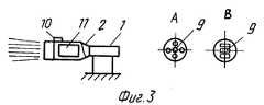
Предлагаемое изобретение поясняется графическим материалом. На фиг. 1 показана установка газодинамического тушения (УГДТ) с насадком закрытого типа; на фиг. 2 - с насадком открытого (эжекторного) типа; на фиг. 3 - с дожигателем, где 1 - реактивный авиационный двигатель типа ТРД, 2 - насадок, 3 - наконечник, 4 - патрубки подачи охлаждающих и пожаротушащих компонентов, 5 - газодинамический поток, 6 - реактивный авиационный двигатель типа ТВД (турбовинтовой двигатель), 7 - отверстие эжекторного типа, 8 - ствольные выходы (лафетные стволы), 9 - выходные отверстия наконечника, 10 - предохранительный клапан, 11 - дожигатель продуктов сгорания реактивного двигателя. The invention is illustrated in graphic material. In FIG. 1 shows the installation of gas-dynamic quenching (UGDT) with a nozzle closed type; in FIG. 2 - with nozzle open (ejector) type; in FIG. 3 - with an afterburner, where 1 is a turbojet jet engine, 2 is a nozzle, 3 is a nozzle, 4 is a nozzle for supplying cooling and fire extinguishing components, 5 is a gas-dynamic flow, 6 is a jet engine of the type TVD (turboprop engine), 7 - an ejector-type hole, 8 — barrel exits (fire monitors), 9 — tip outlet openings, 10 — safety valve, 11 — jet engine afterburner.
Установка для тушения пожаров снабжена реактивным авиационным двигателем типа ТРД (1) и/или ТВД (6). К двигателю крепится насадок (2), который может быть одинарным или составным, состоящим из нескольких частей-секций, соединенных между собой. Длина, диаметр и форма насадка выбираются с учетом мощности двигателя, очага пожара и расстояния до него, а также с учетом внешнего окружения и рельефа местности. Насадок имеет наконечник (3), который может менять свое положение в разных плоскостях, что достигается при его установке или в процессе работы при помощи поворотного устройства ( не показано). Насадок снабжен патрубками (4) для подачи в газовый поток охлаждающих и пожаротушащих компонентов (жидких, порошковообразных, газообразных), выбор которых зависит от горящих материалов и категории пожара. Для подсоса воздуха используются отверстия-щели (7), а наконечник может иметь несколько выходов различной конфигурации, например, выполненных в виде лафетных стволов (8) или другой формы (9). Насадок снабжен предохранительным клапаном (10), через который производится сброс избыточного давления газа 4. Дожигатель (11) продуктов сгорания двигателя устанавливается на срезе сопла в насадке или перед ним. Тип и мощность двигателя выбираются в зависимости от типа и мощности двигателя. The fire extinguishing installation is equipped with a jet engine such as turbojet engine (1) and / or theater (6). Attached to the engine nozzles (2), which can be single or composite, consisting of several parts-sections, interconnected. The length, diameter and shape of the nozzle are selected taking into account the power of the engine, the source of the fire and the distance to it, as well as taking into account the external environment and terrain. The nozzle has a tip (3), which can change its position in different planes, which is achieved when installing it or during operation using a rotary device (not shown). The nozzles are equipped with nozzles (4) for supplying cooling and fire extinguishing components (liquid, powder, gaseous) into the gas stream, the choice of which depends on the burning materials and the fire category. Holes-slots (7) are used to suck in air, and the tip can have several outlets of various configurations, for example, made in the form of fire monitors (8) or another shape (9). The nozzle is equipped with a safety valve (10) through which the excess gas pressure is released 4. The afterburner (11) of the engine combustion products is installed on the nozzle exit in the nozzle or in front of it. The type and power of the engine are selected depending on the type and power of the engine.
Рассмотрим на общем примере использование УГДТ, снабженной наконечником и дожигателем и имеющей составной насадок. Let us consider, using a general example, the use of UGDT equipped with a tip and afterburner and having a composite nozzle.
После доставки УГДТ к месту пожара производится крепление дожигателя (11) к двигателю (1), устанавливается начальная часть насадка (2), к которой пристыковываются в определенной последовательности другие части-секции, к последней из них присоединяется наконечник (3). Затем подсоединяются трубопроводы к патрубкам (4) для подачи необходимых компонентов, например, пенного порошка. После этого производится проверка всех систем УГДТ, заправка топливом и подается команда на пуск установки, включая запуск двигателя, дожигателя и системы подачи компонентов. After UGDT is delivered to the fire place, the afterburner (11) is secured to the engine (1), the initial part of the nozzle (2) is installed, to which other parts-sections are docked in a certain sequence, the tip (3) is attached to the last one. Then the pipelines are connected to the nozzles (4) to supply the necessary components, for example, foam powder. After that, all UGDT systems are checked, refueling and a command is given to start the installation, including starting the engine, afterburner and component supply system.
Через наконечник (3) и его выходные отверстия (8, 9) газовый поток направляется в сторону пожара. Поворотом наконечника достигается равномерное распределение газового потока (5) по всей площади и объему тушения. Поворачивая наконечник (3) в вертикальной плоскости, производится заброс пожаротушащих компонентов в отдаленные или недоступные для прямого воздействия очаги пожара, а также тушить пожар по всей высоте. Кроме того, возможно введение наконечника непосредственно в зону пожара, включая непосредственно очаг пожара. Through the tip (3) and its outlet openings (8, 9), the gas flow is directed towards the fire. By turning the tip, a uniform distribution of the gas stream (5) is achieved over the entire area and volume of the quenching. Turning the tip (3) in a vertical plane, fire extinguishing components are thrown into the fire centers that are remote or inaccessible to direct impact, and also extinguish the fire at full height. In addition, it is possible to introduce the tip directly into the fire zone, including directly the fire site.
После завершения тушения пожара производится включение УГДТ, снимается наконечник, насадок, дожигатель, отсоединяются трубопроводы. Установка доставляется на место ее постоянной дислокации, где она проходит соответствующую подготовку 3 к следующей работе. After completion of the fire extinguishing, the UGDT is turned on, the tip, nozzles, afterburner are removed, the pipelines are disconnected. The installation is delivered to the place of its permanent deployment, where it undergoes appropriate preparation 3 for the next work.
Применение предлагаемой УГДТ позволит эффективней тушить различные пожары, что достигается применением составного насадка и сменных наконечников, имеющих различной конфигурации выходы, так как позволяет сконцентрировать газовый поток в одном или нескольких направлениях, а перемещение наконечника в разных плоскостях позволяет тушить пожар как по площади, так и по всему объему. The application of the proposed UGDT will more effectively extinguish various fires, which is achieved by using a composite nozzle and interchangeable tips having different configurations of outputs, since it allows you to concentrate the gas flow in one or several directions, and moving the tip in different planes allows you to extinguish the fire both in area and in throughout the volume.
Claims (4)
Translated fromRussianPriority Applications (1)
| Application Number | Priority Date | Filing Date | Title |
|---|---|---|---|
| RU96119314ARU2118552C1 (en) | 1996-09-27 | 1996-09-27 | Fire-extinguishing unit |
Applications Claiming Priority (1)
| Application Number | Priority Date | Filing Date | Title |
|---|---|---|---|
| RU96119314ARU2118552C1 (en) | 1996-09-27 | 1996-09-27 | Fire-extinguishing unit |
Publications (2)
| Publication Number | Publication Date |
|---|---|
| RU2118552C1true RU2118552C1 (en) | 1998-09-10 |
| RU96119314A RU96119314A (en) | 1999-01-10 |
Family
ID=20185973
Family Applications (1)
| Application Number | Title | Priority Date | Filing Date |
|---|---|---|---|
| RU96119314ARU2118552C1 (en) | 1996-09-27 | 1996-09-27 | Fire-extinguishing unit |
Country Status (1)
| Country | Link |
|---|---|
| RU (1) | RU2118552C1 (en) |
Cited By (3)
| Publication number | Priority date | Publication date | Assignee | Title |
|---|---|---|---|---|
| RU2238777C2 (en)* | 2003-01-10 | 2004-10-27 | Муниципальное образовательное учреждение дополнительного образования аэрокосмическая школа | Fire fighting device |
| RU2456433C1 (en)* | 2010-12-16 | 2012-07-20 | Закрытое акционерное общество "Источник Плюс" | Fire-fighting method for blow-outs on gas, oil and gas-oil wells |
| CN103656926A (en)* | 2013-12-03 | 2014-03-26 | 天津航空机电有限公司 | Fire extinguishing nozzle for aircraft engine compartment |
Citations (1)
| Publication number | Priority date | Publication date | Assignee | Title |
|---|---|---|---|---|
| SU1639667A1 (en)* | 1989-03-03 | 1991-04-07 | Академия гражданской авиации | Method of extingushing fire on burning surface and fire-fighting appliance |
- 1996
- 1996-09-27RURU96119314Apatent/RU2118552C1/enactive
Patent Citations (1)
| Publication number | Priority date | Publication date | Assignee | Title |
|---|---|---|---|---|
| SU1639667A1 (en)* | 1989-03-03 | 1991-04-07 | Академия гражданской авиации | Method of extingushing fire on burning surface and fire-fighting appliance |
Non-Patent Citations (2)
| Title |
|---|
| WO 93/18823 30.09.93.* |
| Пожарная техника. /Под ред.Безбородько М.Д. - М.: Стройиздат, 1989, с. 120 - 127.* |
Cited By (3)
| Publication number | Priority date | Publication date | Assignee | Title |
|---|---|---|---|---|
| RU2238777C2 (en)* | 2003-01-10 | 2004-10-27 | Муниципальное образовательное учреждение дополнительного образования аэрокосмическая школа | Fire fighting device |
| RU2456433C1 (en)* | 2010-12-16 | 2012-07-20 | Закрытое акционерное общество "Источник Плюс" | Fire-fighting method for blow-outs on gas, oil and gas-oil wells |
| CN103656926A (en)* | 2013-12-03 | 2014-03-26 | 天津航空机电有限公司 | Fire extinguishing nozzle for aircraft engine compartment |
Similar Documents
| Publication | Publication Date | Title |
|---|---|---|
| JP2795444B2 (en) | Flame control method and apparatus | |
| EP1053935B1 (en) | Method for extinguishing fires from an aircraft and related device | |
| JP2916195B2 (en) | Spray nozzle for fire extinguishing, fire extinguishing system and fire extinguishing method | |
| CA2578567C (en) | Fire fighting nozzle for projecting fog cloud | |
| RU2118552C1 (en) | Fire-extinguishing unit | |
| KR100516474B1 (en) | Mist injection apparatus, and fire engine therewith | |
| US20230405379A1 (en) | Device for generating a jet of two-phase fluid | |
| RU34374U1 (en) | Universal heat gas generating unit | |
| WO2021204306A1 (en) | Fire extinguishing equipment with fire nozzle | |
| US3533473A (en) | Foam generator firefighting method | |
| RU2130793C1 (en) | Method of vertical extinguishing, containing of fire | |
| RU2452542C1 (en) | System of fire fighting in vertical reservoirs | |
| RU2109535C1 (en) | Plant for gas-dynamic fire extinguishing | |
| CA2255079A1 (en) | Nozzle | |
| RU2037321C1 (en) | Method and device for extinguishing fire in gas, oil and gas-oil well gushers | |
| RU2058169C1 (en) | Foam-generator | |
| RU2039212C1 (en) | Method to fight fire of spouts on oil, gas, gas and oil boreholes | |
| RU2770220C1 (en) | Method for extinguishing well fire with gas extinguishing agent and device for its implementation | |
| SU733699A1 (en) | Plant for gas-water extinguishing of gusher fire at gas, oil and gas-oil wells | |
| CN223439066U (en) | Nozzle of live water cloud fire-fighting water spraying equipment, live water cloud fire-fighting water gun and water cannon | |
| SU1553145A1 (en) | Method of fire-extinguishing highly inflammable liquid stored in tanks | |
| CN1323235A (en) | Method and device for fighting fires | |
| JP2005027765A (en) | Fire extinguishing method and equipment | |
| RU2721193C1 (en) | Fire truck and foam generator | |
| SU1724275A1 (en) | Device for extinguishing fire on flying vehicle at airfield |