RU2115991C1 - Liquid-filled submersible electric motor - Google Patents
Liquid-filled submersible electric motorDownload PDFInfo
- Publication number
- RU2115991C1 RU2115991C1RU95120844ARU95120844ARU2115991C1RU 2115991 C1RU2115991 C1RU 2115991C1RU 95120844 ARU95120844 ARU 95120844ARU 95120844 ARU95120844 ARU 95120844ARU 2115991 C1RU2115991 C1RU 2115991C1
- Authority
- RU
- Russia
- Prior art keywords
- electric motor
- motor
- liquid
- pressure
- fluid
- Prior art date
Links
Images
Landscapes
- Structures Of Non-Positive Displacement Pumps (AREA)
Abstract
Description
Translated fromRussianИзобретение относится к погружным заполненным жидкостью электродвигателям, предназначенным для привода погружных вращающихся центробежных, винтовых и других насосов для добычи жидкости из скважин, работы в резервуарах, водоемах и т.д. The invention relates to submersible fluid-filled motors designed to drive submersible rotating centrifugal, screw and other pumps for extracting fluid from wells, working in tanks, ponds, etc.
Известен погружной заполненный маслом электродвигатель, который включает эластичную диафрагму для поддержания давления масла внутри электродвигателя равным давлению окружающей жидкости, уплотнение рабочего конца вала в виде сальника и турбинку для создания избыточного давления на сальнике [1]. Known submersible oil-filled electric motor, which includes an elastic diaphragm to maintain the oil pressure inside the electric motor equal to the pressure of the surrounding fluid, sealing the working end of the shaft in the form of an oil seal and a turbine to create excess pressure on the oil seal [1].
Надежность вышеуказанного электродвигателя недостаточно высока. В известной конструкции не исключаются проникновение окружающей жидкости в полость электродвигателя и повышенный расход масла через сальник, расположенный на рабочем конце вала, при пусках, остановках электродвигателя, а также при спуско-подъемных операциях из-за низкой надежности сальника. The reliability of the above electric motor is not high enough. In the known design, the penetration of the surrounding fluid into the cavity of the electric motor and increased oil consumption through the oil seal located on the working end of the shaft during starts, stops the electric motor, as well as during tripping and lifting operations due to the low reliability of the oil seal are not excluded.
Дублирование уплотнения для защиты рабочего конца вала в известной конструкции не предусмотрено. Кроме того, установка эластичной диафрагмы над вращающимся валом усложняет конструкцию и снижает ее технологичность. Duplication of the seal to protect the working end of the shaft in the known design is not provided. In addition, the installation of an elastic diaphragm above a rotating shaft complicates the design and reduces its manufacturability.
Известно выполненное в виде отдельного узла устройство для гидравлической защиты погружного маслозаполненного электродвигателя, состоящее из вала, твердых уплотнений, корпуса, камер, связанных гидравлически между собой последовательно с помощью трубок. В средней и нижней камерах устройства между торцевыми уплотнениями и корпусом установлена эластичная диафрагма, охватывающая вращающийся вал, и в каждой из камер находится сбрасывающий клапан. В устройстве для защиты от проникновения окружающей жидкости по валу предусмотрено дублирование торцевых уплотнений, а для исключения проникновения пластовой жидкости другим путем имеются барьерная жидкость, лабиринт, образованный трубками, и диафрагма. Между торцевыми уплотнениями в верхнем фланце имеется камера, связанная каналом с наддиафрагменной полостью, которая через трубку сообщается с внешней камерой [2]. A device for the hydraulic protection of a submersible oil-filled electric motor, made up of a shaft, solid seals, housing, chambers, hydraulically interconnected in series using tubes, is known to be a separate unit. In the middle and lower chambers of the device between the mechanical seals and the housing there is an elastic diaphragm covering the rotating shaft, and in each of the chambers there is a relief valve. The device for protection against penetration of surrounding fluid along the shaft provides for duplication of mechanical seals, and to prevent penetration of the reservoir fluid in another way, there is a barrier fluid, a labyrinth formed by tubes, and a diaphragm. Between the end seals in the upper flange there is a chamber connected by a channel with a supra-diaphragm cavity, which communicates through an tube with an external chamber [2].
Известное устройство является конструктивно сложным, отдельным от электродвигателя изделием, включающим в себя радиальный и упорный подшипники, относительно большое количество корпусных деталей и исполнительных элементов (торцевые уплотнения, диафрагмы, сбрасывающие клапаны, барьерная жидкость, соединительные трубки). The known device is structurally complex, separate from the electric motor, including radial and thrust bearings, a relatively large number of body parts and actuators (mechanical seals, diaphragms, relief valves, barrier fluid, connecting tubes).
Большое количество деталей и сборочных единиц, последовательная гидравлическая связь между камерами через отверстия и соединительные трубки не только усложняют конструкцию, но снижают надежность при эксплуатации и технологичность при изготовлении погружного электродвигателя в целом. Наличие отдельного от электродвигателя устройства для гидравлической защиты, которое подсоединяется к электродвигателю на месте эксплуатации, усложняет монтажные работы и работы при подготовке к монтажу. A large number of parts and assembly units, a consistent hydraulic connection between the chambers through the holes and connecting tubes not only complicate the design, but also reduce operational reliability and manufacturability in the manufacture of the submersible motor as a whole. The presence of a device for hydraulic protection separate from the electric motor, which is connected to the electric motor at the place of operation, complicates installation work and work in preparation for installation.
Известен погружной заполненный жидкостью электродвигатель, содержащий компенсатор давления, расположенный в его нижней части, и торцевое уплотнение вала, установленное на рабочем конце последнего таким образом, что невращающееся кольцо закреплено в верхнем фланце электродвигателя, а вращающееся зафиксировано на валу. Основным недостатком известного устройства можно считать низкую надежность, т.к. в устройстве не предусмотрено дублирование элементов защиты от проникновения жидкости извне и отсутствуют специальные меры по устранению "гидравлического удара" на торцевые уплотнения при резком изменении давления внутри электродвигателя [3]. Known submersible fluid-filled electric motor containing a pressure compensator located in its lower part, and a mechanical shaft seal mounted on the working end of the latter so that a non-rotating ring is fixed in the upper flange of the motor, and the rotating is fixed on the shaft. The main disadvantage of the known device can be considered low reliability, because the device does not provide for duplication of protection elements from liquid penetration from the outside and there are no special measures to eliminate the "water hammer" on the mechanical seals with a sharp change in pressure inside the motor [3].
Наиболее близким к предлагаемому является погружной маслозаполненный электродвигатель для привода насосов, в нижней части которого размещен гидравлический компенсатор давления, а в верхней части установлен протектор, разделенный эластичной диафрагмой на две камеры. Протектор содержит корпус, радиальные подшипники, эластичную диафрагму, вал для передачи вращения от электродвигателя к насосу и торцевое уплотнение. Вращающееся кольцо упомянутого уплотнения зафиксировано в осевом направлении относительно его неподвижной части, в свою очередь, зафиксированной в корпусе. В корпусе протектора имеется также сбрасывающий клапан [4]. Closest to the proposed one is a submersible oil-filled electric motor for driving pumps, in the lower part of which a hydraulic pressure compensator is located, and in the upper part there is a tread divided by an elastic diaphragm into two chambers. The tread comprises a housing, radial bearings, an elastic diaphragm, a shaft for transmitting rotation from the electric motor to the pump, and a mechanical seal. The rotating ring of said seal is axially fixed relative to its fixed part, which in turn is fixed in the housing. There is also a relief valve [4] in the tread case.
Однако надежность известного электродвигателя недостаточна из-за отсутствия последовательного дублирования элементов, обеспечивающих герметичность электродвигателя со стороны рабочего конца вала (торцевых уплотнений), и возможности передачи через стенки эластичной диафрагмы резкого изменения давления во внутренней полости электродвигателя ("гидравлического удара") на уплотнение, что способствует образованию зазора между торцами вращающегося и невращающегося колец уплотнения и уходу жидкости из полости электродвигателя. Многократное резкое изменение давления во внутренней полости электродвигателя происходит при спуско-подъемных операциях при монтаже электродвигателя в скважину, что снижает надежность работы изделия в целом. However, the reliability of the known electric motor is insufficient due to the lack of sequential duplication of elements ensuring the tightness of the electric motor on the side of the working end of the shaft (mechanical seals) and the possibility of transmitting through the walls of the elastic diaphragm a sharp change in pressure in the internal cavity of the electric motor ("hydraulic shock") to the seal, which contributes to the formation of a gap between the ends of the rotating and non-rotating rings of the seal and the escape of fluid from the cavity of the electric motor. A multiple sharp change in pressure in the internal cavity of the electric motor occurs during tripping during installation of the electric motor in the well, which reduces the reliability of the product as a whole.
Компоновка погружного электродвигателя имеет большие габариты по длине и не удобна из-за того, что протектор, компенсатор, электродвигатель являются отдельными сборочными единицами и окончательная сборка погружного электродвигателя производится непосредственно на устье скважины, при этом компенсатор размещается под электродвигателем, а протектор - в верхней его части. Кроме этого, в качестве жидкости в известной конструкции используется масло, что ограничивает его применение там, где имеются экологические ограничения. The layout of the submersible motor is large in length and is not convenient due to the fact that the tread, compensator, electric motor are separate assembly units and the final assembly of the submersible motor is carried out directly at the wellhead, while the compensator is located under the electric motor, and the protector is in its upper parts. In addition, oil is used as a liquid in a known construction, which limits its use where environmental restrictions exist.
Цель изобретения создать такой погружной заполненный жидкостью электродвигатель, в котором новое выполнение компоновки, обеспечивающее защиту по валу с помощью двух торцевых уплотнений, установленных в верхней части двигателя, герметичной, заполненной жидкостью камеры, торцами которой являются встречно перемещающиеся в осевом направлении невращающиеся кольца уплотнений, причем на боковой стенке камеры должен быть упор для последних, создает одновременное последовательное дублирование защиты полости двигателя как по валу, так и по корпусу, одним узлом, что обеспечивает высокую надежность при минимальных габаритах по длине и, следовательно, возможность полной сборки устройства в заводских условиях, т.к. нет ограничений на транспортировку электродвигателя в сборе. The purpose of the invention is to create such a submersible fluid-filled electric motor, in which a new embodiment of the arrangement, providing protection along the shaft with two mechanical seals installed in the upper part of the engine, is hermetic, fluid-filled chamber, the ends of which are non-rotating ring of seals opposite to the axially moving, moreover there should be an emphasis on the side wall of the chamber for the latter, creating simultaneous sequential duplication of protection of the engine cavity both along the shaft and along one unit, which provides high reliability with minimum dimensions along the length and, therefore, the ability to fully assemble the device in the factory, because There are no restrictions on the transportation of the motor assembly.
Для достижения поставленной цели погружной заполненный жидкостью электродвигатель, содержащий компенсатор давления, расположенный в его нижней части, корпус и торцевое уплотнение вала, невращающееся кольцо которого установлено в верхней части электродвигателя, а также сбрасывающий клапан, согласно изобретению содержит дополнительное торцевое уплотнение, при этом невращающиеся кольца торцевых уплотнений закреплены в корпусе с возможностью осевого встречного перемещения, а между ними образована герметичная, заполненная жидкостью камера, на боковой стенке которой расположены упорные поверхности для указанных невращающихся колец. To achieve the goal, a submersible fluid-filled electric motor containing a pressure compensator located in its lower part, a housing and a mechanical shaft seal, a non-rotating ring of which is installed in the upper part of the electric motor, and a relief valve, according to the invention, contains an additional mechanical seal, with non-rotating rings mechanical seals are fixed in the housing with the possibility of axial onward movement, and between them is sealed, filled with liquid to measure, on the side wall which are arranged for abutment surfaces of said non-rotating rings.
Наличие дополнительной герметичной камеры в верхней части электродвигателя, торцы которой образованы невращающимися кольцами торцевых уплотнений, которые имеют возможность осевого встречного перемещения, исключает непосредственное воздействие гидравлического удара на торцевые уплотнения, т.к. торцы камеры отслеживают изменения давления внутри полости электродвигателя или извне, что повышает надежность без увеличения габаритов и усложнения конструкции, а это позволяет полностью собирать двигатель в заводских условиях и транспортировать к месту эксплуатации в сборе, что также повышает надежность. The presence of an additional sealed chamber in the upper part of the electric motor, the ends of which are formed by non-rotating rings of the mechanical seals, which have the possibility of axial onward movement, excludes the direct impact of hydraulic shock on the mechanical seals, as the ends of the chamber monitor pressure changes inside the cavity of the electric motor or from the outside, which increases reliability without increasing the size and complexity of the design, and this allows you to completely assemble the engine in the factory and transport it to the place of operation, which also increases reliability.
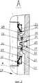
На фиг. 1 представлен предлагаемый электродвигатель в продольном разрезе; на фиг. 2 - узел А на фиг. 1. In FIG. 1 shows the proposed electric motor in longitudinal section; in FIG. 2 - node A in FIG. one.
Погружной электродвигатель 1 содержит статор 2, ротор 3, вал 4 и заполнен жидкостью 5. Используется электродвигатель 1 для привода насоса 6. В нижней части к электродвигателю 1 подсоединен гидравлический компенсатор 7 давления, который при помощи эластичной диафрагмы 8 поддерживает давление жидкости 5 внутри электродвигателя 1 равным давлению окружающей жидкости 9. В верхнем фланце 10 корпуса 11 электродвигателя 1 установлены торцевые уплотнения 12 и 13, предотвращающие попадание окружающей жидкости 9 вовнутрь электродвигателя по рабочему концу вала 4. Между торцевыми уплотнениями 12 и 13 образована герметичная камера 14, заполненная, например, той же жидкостью, что и полость электродвигателя. The submersible motor 1 contains a stator 2, a rotor 3, a shaft 4 and is filled with liquid 5. An electric motor 1 is used to drive the pump 6. At the bottom, a hydraulic pressure compensator 7 is connected to the electric motor 1, which, with the help of an elastic diaphragm 8, supports the pressure of the liquid 5 inside the electric motor 1 equal to the pressure of the surrounding fluid 9. In the upper flange 10 of the housing 11 of the motor 1 is installed mechanical seals 12 and 13, preventing the ingress of the surrounding fluid 9 into the motor along the working end in Ala 4. Between the mechanical seals 12 and 13, a sealed chamber 14 is formed, filled, for example, with the same liquid as the cavity of the electric motor.
Невращающиеся кольца 15 и 16 торцевых уплотнений 12 и 13 имеют возможность встречного перемещения вдоль оси 17. Корпус 18, охватывающий эластичную диафрагму 8 компенсатора 7, имеет внутреннюю поверхность 19, идентичную наружной поверхности 20 эластичной диафрагмы 8, и ограничивает ее перемещение вдоль оси 17 и в направлении радиуса 21. Отверстие 22 для прохода окружающей жидкости 9 к эластичной диафрагме 8 расположено в нижней части корпуса 18. Над верхним торцом 23 корпуса 18 эластичной диафрагмы 8 установлен сбрасывающий избыточное давление клапан 24.
Для прохода жидкости 5 в полость диафрагмы 8 компенсатора 7 в торце 23 имеются отверстия 25. Кроме того, для обеспечения заполнения полости электродвигателя 1 в его корпусе предусмотрено отверстие 26, а также используется отверстие под клапан 24, в которое устанавливается клапан для закачки (не показано). Для заполнения камеры 14 используется отверстие 27. По окончании заполнения устанавливается сбрасывающий клапан 24, а отверстия 26 и 27 закрываются пробками (на чертеже не показаны). To pass the fluid 5 into the cavity of the diaphragm 8 of the compensator 7, there are openings 25 in the end face 23. In addition, to ensure the filling of the cavity of the electric motor 1, a hole 26 is provided in its body, and a hole for the valve 24 is used, into which an injection valve is installed (not shown ) A
Торцевые уплотнения 12 и 13, помимо невращающихся колец 15 и 16, содержат соответственно вращающиеся кольца 28 и 29, сильфоны 30 и 31, пружины 32 и 33, уплотнительные кольца 34 и 35. Для невращающихся колец 15 и 16, имеющих возможность встречного осевого перемещения, на боковой стенке герметичной камеры 14 выполнены упорные поверхности 36 и 37. The mechanical seals 12 and 13, in addition to the
Усилием пружины 33 вращающееся кольцо 29 прижато к невращающемуся кольцу 16, а кольцо 16 - к поверхности 37. Усилием пружины 32 вращающееся кольцо 28 прижато к невращающемуся кольцу 15, а кольцо 15 - к поверхности 36. Сильфон 31 герметично установлен к поверхности вала 4 и вращающемуся кольцу 29, а сильфон 30 герметично установлен к поверхности вала 4 и вращающемуся кольцу 28. Невращающееся кольцо 16 герметично установлено в верхнем фланце 10 при помощи уплотнительного кольца 35, а невращающееся кольцо 15 - при помощи уплотнительного кольца 34. Неподвижность колец 15 и 16 в тангенциальном направлении обеспечивается силами трения уплотнительных колец 34, 35 по боковой поверхности камеры 14 в верхнем фланце 10. Вращающиеся кольца 28, 29 удерживаются в неподвижном состоянии относительно вала 4 силами трения сильфонов 30, 31 по поверхности вала 4. Таким образом, герметичность камеры 14 обеспечена. By the force of the
Заполнение электродвигателя 1 жидкостью 5 производится следующим образом. Filling the motor 1 with liquid 5 is as follows.
Вместо сбрасывающего клапана 24 устанавливается клапан для закачки (на чертеже не показан). Жидкость 5 через отверстия 25 заполняет внутреннюю полость эластичной диафрагмы 8 и далее через зазор между статором 2 и ротором 3 до появления жидкости 5 из отверстия 26. Instead of a discharge valve 24, an injection valve is installed (not shown in the drawing). The liquid 5 through the holes 25 fills the internal cavity of the elastic diaphragm 8 and then through the gap between the stator 2 and the rotor 3 until the liquid 5 appears from the hole 26.
Заполнение герметичной камеры 14 жидкостью 5 производится при сборке электродвигателя или через отверстие 27. The hermetic chamber 14 is filled with liquid 5 when the electric motor is assembled or through the
При погружении электродвигателя 1 окружающая жидкость 9 проникает в отверстие 22 и эластичная диафрагма 8 сжимается в направлении к оси 17, выравнивая давления окружающей жидкости 9 и жидкости 5 внутри электродвигателя 1. Кроме этого, окружающая жидкость 9 заполняет объем над торцевым уплотнением 12. When the motor 1 is immersed, the surrounding fluid 9 penetrates the hole 22 and the elastic diaphragm 8 contracts toward the
При работе электродвигателя 1 жидкость 5 увеличивается в объеме от нагрева статора 2, ротора 3 и других источников тепла, и эластичная диафрагма 8 возвращается в исходное положение и далее прижимается ко внутренней поверхности 19 корпуса 18. В случае продолжения увеличения объема жидкости 5 от нагрева во внутренней полости электродвигателя 1 возникает давление, превышающее давление окружающей жидкости 9, тогда увеличивается расход жидкости 5 между вращающимся кольцом 29 и невращающимся кольцом 16 торцевого уплотнения 13, при этом давление жидкости 5 уравнивается с давлением в камере 14. В экстремальном случае, когда резко увеличивается давление жидкости 5 во внутренней полости электродвигателя 1 от превышения допустимого перегрева или др. ("гидравлический удал"), срабатывает клапан 24 и сбрасывает избыточное давление жидкости 5. When the motor 1 is operating, the liquid 5 increases in volume from the heating of the stator 2, rotor 3 and other heat sources, and the elastic diaphragm 8 returns to its original position and then presses against the inner surface 19 of the housing 18. If the increase in the volume of the liquid 5 continues from heating in the inner the cavity of the motor 1 there is a pressure exceeding the pressure of the surrounding fluid 9, then the flow rate of fluid 5 between the rotating
Работоспособное состояние герметичной камеры 14, выравнивание давлений жидкости 5 в герметичной камере 14, во внутренней полости электродвигателя 1 и давления окружающей жидкости 9 обеспечивается возможностью осевого перемещения невращающихся колец 15 и 16 без нарушения герметичности по боковой поверхности камеры 14 в верхнем фланце 10. The operational state of the sealed chamber 14, the equalization of the pressure of the liquid 5 in the sealed chamber 14, in the inner cavity of the motor 1 and the pressure of the surrounding liquid 9 is ensured by the possibility of axial movement of the
Обозначив давление окружающей жидкости 9 через Pо, давление жидкости 5 в дополнительной герметичной камере 14 - Pк и давление жидкости 5 в полости электродвигателя 1, т.е. под диафрагмой 8, - Pд, рассматриваем несколько основных условий, которые могут возникнуть при работе электродвигателя 1.Denoting the pressure of the surrounding fluid 9 by Po , the fluid pressure 5 in the additional sealed chamber 14 - Pk and the fluid pressure 5 in the cavity of the electric motor 1, i.e. under the diaphragm 8, - Pd , we consider several basic conditions that may arise when the motor 1.
Условие А. Давление Pо = Pд = Pк, т.е. исходное положение на поверхности земли или при погружении электродвигателя 1 в жидкость 9.Condition A. Pressure Po = Pd = Pk , i.e. initial position on the surface of the earth or when the motor 1 is immersed in a liquid 9.
Условие Б. Давление Pк > Pо = Pд, т.е. электродвигатель 1 работает, температура жидкости 5 в герметичной камере 14 повысилась, увеличился ее объем, следовательно, при постоянном объеме камеры 14 увеличилось давление жидкости 5. Давление Pо = Pд уравновешено эластичной диафрагмой 8. Сила, действующая на невращающееся кольцо 15, равна произведению (Pк - Pо) на площадь его поверхности, контактирующей с упорной поверхностью 36, преодолевая усилие пружины 32 и силу трения резинового кольца 24 по поверхности фланца 10 в камере 14, переместит невращающееся кольцо 15 к кольцу 28. Сила, действующая на невращающееся кольцо 16, равная произведению (Pк - Pд) на площадь его поверхности, контактирующей с упорной поверхностью 37, преодолевая усилие пружины 33 и силу трения резинового кольца 35 по поверхности верхнего фланца 10 в камере 14, переместит невращающееся кольцо 16 в направлении к кольцу 29. При этом объем герметичной камеры 14 увеличится, следовательно, давление Pк уменьшится и будет примерно равно давлению Pо = Pд. Таким образом, герметичность камеры 14 обеспечена, и уравновешено давление на торцевых уплотнениях 12 и 13, что является основным условием надежной работы торцевых уплотнений.Condition B. Pressure Pк > Pо = Pд , i.e. the electric motor 1 is operating, the temperature of the liquid 5 in the sealed chamber 14 has increased, its volume has increased, therefore, with a constant volume of the chamber 14, the pressure of the liquid 5 has increased. The pressure Po = Pd is balanced by the elastic diaphragm 8. The force acting on the
Условие В. Давление Pд> Pк > Pо, т.е. электродвигатель работает, температура жидкости 5 в герметичной камере 14 установилась, а в полости электродвигателя 1 (под эластичной диафрагмой 8) температура повысилась, следовательно, увеличился объем жидкости 5, и давление Pд превышает давление Pк. Сила, действующая на невращающееся кольцо 16, под действием давления (Pд - Pк) переместит кольцо 16 в сторону упорной поверхности 37. Кольцо 29 также переместится в том же направлении под воздействием пружины 33. При этом объем герметичной камеры 14 уменьшится, следовательно, давление Pк увеличится. Поэтому кольцо 15 переместится в сторону кольца 28. Перепад давления на торцевом уплотнении 13 будет примерно равен нулю, а на торцевом уплотнении 12 увеличится, следовательно, расход жидкости 5 между кольцами 15 и 28 увеличится, следовательно, уменьшится перепад давления на торцевом уплотнении 12. Таким образом, перепад давления на торцевых уплотнениях 12, 13 уравновесится, и герметичность камеры 14 обеспечится.Condition B. Pressure Pd > Pk > Po , i.e. the electric motor works, the temperature of the liquid 5 in the sealed chamber 14 is established, and in the cavity of the electric motor 1 (under the elastic diaphragm 8) the temperature has increased, therefore, the volume of the liquid 5 has increased, and the pressure Pd exceeds the pressure Pk . The force acting on the
Условие Г. Электродвигатель 1 длительное время работает без остановок, т. е. режим работы установившийся, тогда работоспособность и герметичность камеры 14 соответствуют условию А. Condition D. The electric motor 1 for a long time works without stops, that is, the operating mode is steady, then the operability and tightness of the chamber 14 correspond to condition A.
Условие Д. Давление Pо > = Pк > Pд, т.е. после весьма длительной работы электродвигатель 1 остановлен. Так как объем герметичной камеры 14 сравнительно мал, следовательно, уменьшение объема жидкости 5 в герметичной камере 14 при остывании незначительно, тогда Pк = Pо (приблизительно). Кроме того, при Pо > Pк возможно перемещение сильфона 30 в сторону кольца 28 под воздействием давления (Pо - Pк). При остановленном электродвигателе 1 кольца 28, 29 неподвижны, следовательно, расход жидкости 5 отсутствует, герметичность камеры 14 обеспечена. В случае пуска электродвигателя 1 в работу температура жидкости 5 повышается, давление Pд возрастает, электродвигатель выходит на режим условия Г.Condition D. Pressure Pо > = Pк > Pд , i.e. after a very long operation, the electric motor 1 is stopped. Since the volume of the sealed chamber 14 is relatively small, therefore, the decrease in the volume of liquid 5 in the sealed chamber 14 is not significant when cooling, then Pk = Po (approximately). In addition, when Po > Pk it is possible to move the
В процессе работы электродвигателя 1 возможны и другие условия работы, например, Pо = Pк < = Pд или Pо = Pд > Pк, при которых торцевые уплотнения 12 и 13 работают не в критическом режиме.In the process of operation of the electric motor 1, other operating conditions are possible, for example, Po = Pk <= Pd or Po = Pd > Pk , in which the mechanical seals 12 and 13 do not work in critical mode.
Claims (1)
Translated fromRussianPriority Applications (1)
| Application Number | Priority Date | Filing Date | Title |
|---|---|---|---|
| RU95120844ARU2115991C1 (en) | 1995-12-05 | 1995-12-05 | Liquid-filled submersible electric motor |
Applications Claiming Priority (1)
| Application Number | Priority Date | Filing Date | Title |
|---|---|---|---|
| RU95120844ARU2115991C1 (en) | 1995-12-05 | 1995-12-05 | Liquid-filled submersible electric motor |
Publications (2)
| Publication Number | Publication Date |
|---|---|
| RU95120844A RU95120844A (en) | 1997-12-20 |
| RU2115991C1true RU2115991C1 (en) | 1998-07-20 |
Family
ID=20174571
Family Applications (1)
| Application Number | Title | Priority Date | Filing Date |
|---|---|---|---|
| RU95120844ARU2115991C1 (en) | 1995-12-05 | 1995-12-05 | Liquid-filled submersible electric motor |
Country Status (1)
| Country | Link |
|---|---|
| RU (1) | RU2115991C1 (en) |
Cited By (5)
| Publication number | Priority date | Publication date | Assignee | Title |
|---|---|---|---|---|
| RU2192700C1 (en)* | 2001-09-26 | 2002-11-10 | Открытое акционерное общество "Борец" | Submersible oil-filled motor |
| RU2199030C2 (en)* | 2000-08-25 | 2003-02-20 | Производственный комплекс "Альметьевский насосный завод" АО "АЛНАС" | Protector for hydraulic protection of submersible oil-filled electric motor |
| RU2236742C2 (en)* | 2002-08-30 | 2004-09-20 | Общество с ограниченной ответственностью "Центр исследований и разработок ЮКОС" | Submersible electric motor |
| RU2485660C2 (en)* | 2011-09-22 | 2013-06-20 | Открытое акционерное общество "Татнефть" им. В.Д. Шашина | Submersible motor with increased power factor |
| RU2615542C2 (en)* | 2013-02-26 | 2017-04-05 | Иглбургманн Джермани Гмбх Унд Ко. Кг | Well transport device |
Citations (3)
| Publication number | Priority date | Publication date | Assignee | Title |
|---|---|---|---|---|
| SU436415A1 (en)* | 1971-03-18 | 1974-07-15 | С. Помазкова , А. А. Богданов Особое конструкторское бюро бесштанговым насосам | SUBMERSHIP OIL FILLED MOTOR |
| SU1365255A1 (en)* | 1986-03-14 | 1988-01-07 | Специальное проектно-конструкторское и технологическое бюро по погружному электрооборудованию для бурения скважин и добычи нефти Всесоюзного научно-производственного объединения "Потенциал" | Submersible liquid-filled electric motor |
| SU1483553A1 (en)* | 1987-10-22 | 1989-05-30 | Специальное проектно-конструкторское и технологическое бюро по погружному электрооборудованию для бурения скважин и добычи нефти Всесоюзного научно-производственного объединения "Потенциал" | Apparatus for hydraulic protection of of submersible oil-filled electric motor |
- 1995
- 1995-12-05RURU95120844Apatent/RU2115991C1/enactive
Patent Citations (3)
| Publication number | Priority date | Publication date | Assignee | Title |
|---|---|---|---|---|
| SU436415A1 (en)* | 1971-03-18 | 1974-07-15 | С. Помазкова , А. А. Богданов Особое конструкторское бюро бесштанговым насосам | SUBMERSHIP OIL FILLED MOTOR |
| SU1365255A1 (en)* | 1986-03-14 | 1988-01-07 | Специальное проектно-конструкторское и технологическое бюро по погружному электрооборудованию для бурения скважин и добычи нефти Всесоюзного научно-производственного объединения "Потенциал" | Submersible liquid-filled electric motor |
| SU1483553A1 (en)* | 1987-10-22 | 1989-05-30 | Специальное проектно-конструкторское и технологическое бюро по погружному электрооборудованию для бурения скважин и добычи нефти Всесоюзного научно-производственного объединения "Потенциал" | Apparatus for hydraulic protection of of submersible oil-filled electric motor |
Cited By (5)
| Publication number | Priority date | Publication date | Assignee | Title |
|---|---|---|---|---|
| RU2199030C2 (en)* | 2000-08-25 | 2003-02-20 | Производственный комплекс "Альметьевский насосный завод" АО "АЛНАС" | Protector for hydraulic protection of submersible oil-filled electric motor |
| RU2192700C1 (en)* | 2001-09-26 | 2002-11-10 | Открытое акционерное общество "Борец" | Submersible oil-filled motor |
| RU2236742C2 (en)* | 2002-08-30 | 2004-09-20 | Общество с ограниченной ответственностью "Центр исследований и разработок ЮКОС" | Submersible electric motor |
| RU2485660C2 (en)* | 2011-09-22 | 2013-06-20 | Открытое акционерное общество "Татнефть" им. В.Д. Шашина | Submersible motor with increased power factor |
| RU2615542C2 (en)* | 2013-02-26 | 2017-04-05 | Иглбургманн Джермани Гмбх Унд Ко. Кг | Well transport device |
Similar Documents
| Publication | Publication Date | Title |
|---|---|---|
| RU2609899C1 (en) | Protection of hydraulic submersible motor gages (versions) | |
| US3475634A (en) | Submergible oil-filled electric motor with a protecting unit for the drive of a submergible well pump | |
| GB1248677A (en) | Submersible pump motor seal section | |
| SU436415A1 (en) | SUBMERSHIP OIL FILLED MOTOR | |
| RU2115991C1 (en) | Liquid-filled submersible electric motor | |
| RU2645106C1 (en) | Device for hydraulic protection of submersible oil-filled electric motor | |
| GB2085667A (en) | Submersible electric motors | |
| US4262226A (en) | Insulating fluid system for protecting submersible electric motors from surrounding fluids | |
| US3785753A (en) | Electric drives for centrifugal pumps | |
| RU2646985C1 (en) | Node for hydraulic protection of the submersible oil-completed electric motor (options) | |
| RU2219640C2 (en) | Hydraulic protection device for submersible oilfilled electric motor | |
| SU1429228A1 (en) | Arrangement for hydraulic protection of submersible oil-filled electric motor | |
| RU6650U1 (en) | LIQUID SUBMERSIBLE ELECTRIC MOTOR | |
| RU2210159C2 (en) | Waterproofing device for submersible oil-filled electric motor | |
| RU2023848C1 (en) | Bottom hole engine lubrication protection system | |
| SU1020924A1 (en) | Device for hydraulic protection of submersible oil-filled electric motor | |
| RU2717474C2 (en) | Piston module of device for hydraulic protection of submersible electric motor (embodiments) | |
| RU2194349C1 (en) | Device for hydraulic protection of submersible oil- filled electric motor | |
| RU2272117C2 (en) | Downhole motor spindle | |
| RU2800766C1 (en) | Device for hydraulic protection of submersible oil-filled electric motor | |
| RU2038673C1 (en) | Liquid-filled vertical-shaft electrical machine | |
| RU2234785C2 (en) | Device for hydraulic protection of submersible oil-filled electric motor | |
| SU843107A1 (en) | Device for protecting immersion pump electric motor | |
| RU2221322C2 (en) | Device for protecting electric motor against stratal liquid | |
| SU1693689A1 (en) | Device for protecting submersible motor |