RU2115798C1 - Non-return valve for casing strings - Google Patents
Non-return valve for casing stringsDownload PDFInfo
- Publication number
- RU2115798C1 RU2115798C1RU96100720/03ARU96100720ARU2115798C1RU 2115798 C1RU2115798 C1RU 2115798C1RU 96100720/03 ARU96100720/03 ARU 96100720/03ARU 96100720 ARU96100720 ARU 96100720ARU 2115798 C1RU2115798 C1RU 2115798C1
- Authority
- RU
- Russia
- Prior art keywords
- valve
- diameter
- ball valve
- ball
- ball lock
- Prior art date
Links
- 230000002093peripheral effectEffects0.000claimsdescription5
- 238000005192partitionMethods0.000claimsdescription3
- 238000007789sealingMethods0.000abstractdescription7
- 239000000126substanceSubstances0.000abstract1
- 238000005553drillingMethods0.000description7
- 239000012530fluidSubstances0.000description7
- 239000004568cementSubstances0.000description6
- 239000002002slurrySubstances0.000description6
- 230000003628erosive effectEffects0.000description5
- 238000011010flushing procedureMethods0.000description4
- 239000011440groutSubstances0.000description3
- 238000000034methodMethods0.000description2
- 230000015572biosynthetic processEffects0.000description1
- 239000007788liquidSubstances0.000description1
- 239000012528membraneSubstances0.000description1
- 239000002184metalSubstances0.000description1
- 239000004570mortar (masonry)Substances0.000description1
Images


Landscapes
- Check Valves (AREA)
Abstract
Description
Translated fromRussianИзобретение относится к области бурения скважин, в частности к устройствам для их цементирования. The invention relates to the field of well drilling, in particular to devices for cementing them.
Известен обратный клапан для обсадных колонн, включающий корпус с размещенным в нем эластичным седлом под шаровой затвор и расположенный под ними жестко связанный с корпусом диск с центральным дросселирующим отверстием и с периферийными промывочными отверстиями, перекрываемыми снизу эластичной мембраной [1]. A non-return valve for casing strings is known, including a housing with an elastic seat located therein for a ball valve and a disk located below them with a central throttling hole and peripheral flushing holes overlapping from below by an elastic membrane [1].
Недостатком этого обратного клапана является низкая надежность заполнения обсадной колонны скважиной жидкостью через дросселирующее отверстие при спуске в скважину из-за постоянного сечения этого отверстия при переменных условиях в скважине. The disadvantage of this check valve is the low reliability of filling the casing with borehole fluid through the throttling hole when it is lowered into the well due to the constant cross-section of this hole under variable conditions in the well.
Известен также обратный клапан для обсадных колонн, свободный от указанного недостатка. Этот клапан, являющийся по технической сущности прототипом предлагаемого клапана, включает корпус с размещенным в нем седлом, подшаровой затвор и расположенный под ними жестко связанный с корпусом диск с перекрываемыми подпружиненной пластиной периферийными отверстиями и установленной в его центральном канале подпружиненной дросселирующей втулкой [2]. A check valve for casing is also known, free of this drawback. This valve, which is the technical essence of the prototype of the proposed valve, includes a housing with a seat located in it, a ball valve and a disk located rigidly connected to the housing with peripheral openings blocked by a spring plate and a spring-loaded throttling sleeve installed in its central channel [2].
Недостатком прототипа является низкая надежность его работы в наклонных и горизонтальных скважинах из-за размыва потоком бурового и особенно тампонажного растворов шарового затвора и отклонения последнего от седла потоком жидкости. The disadvantage of the prototype is the low reliability of its operation in deviated and horizontal wells due to erosion by the flow of drilling and especially cement slurry ball valves and deviations of the latter from the saddle by the fluid flow.
В процессе промывки скважины перед ее цементированием шаровой затвор подвергается воздействию потока бурового раствора и совершает хаотические движения внутри клапана, изнашиваясь при этом, и за счет эрозионного воздействия потоком, и за счет механического трения и ударов о металлические поверхности деталей клапан. In the process of flushing a well before cementing, the ball valve is exposed to the flow of the drilling fluid and makes random movements inside the valve, wearing out due to erosion by the flow, and due to mechanical friction and impacts on the metal surfaces of the valve parts.
Аналогичным образом, но в большей степени шаровой затвор изнашивается в процессе продавливания тампонажного раствора через клапан. Similarly, but to a greater extent, the ball valve wears out during the process of forcing the cement slurry through the valve.
По окончании операции продавливания тампонажного раствора шаровой затвор либо тонет, либо всплывает в нем в зависимости от соотношения его плотности с плотностью тампонажного раствора. At the end of the grouting grouting operation, the ball valve either sinks or floats in it depending on the ratio of its density to the density of the grouting mortar.
Если клапан при этом находится на наклонном участке ствола скважины, шаровой затвор отклоняется от оси клапана, а значит, и его седла в обоих случаях - и когда тонет, и когда всплывает в тампонажном растворе, как это показано на фиг. 4, где изображен клапан-прототип. Положение A и B на фиг. 4 соответствуют утонувшему и всплывшему шару. Восходящий поток тампонажного раствора, направленный вдоль оси клапана (см. по стрелкам C) еще больше отклоняет шар от оси потока и седла. If the valve is located on an inclined section of the wellbore, the ball valve deviates from the axis of the valve, and hence its seat in both cases, when it drowns and when it pops up in the grout, as shown in FIG. 4, which shows a prototype valve. Position A and B in FIG. 4 correspond to a drowned and floating balloon. The upward flow of cement slurry directed along the axis of the valve (see arrows C) further deflects the ball from the axis of flow and seat.
Износом шара и отклонением его от оси потока объясняется большинство фиксируемых случаев отказа обратных клапанов по прототипу из-за негерметичности. The wear of the ball and its deviation from the axis of the flow explains most of the recorded cases of failure of the check valves of the prototype due to leaks.
Целью предлагаемого обратного клапана для обсадных колонн является повышение надежности его работы в наклонных и горизонтальных скважинах путем предотвращения размыва потоком тампонажного раствора шарового затвора и отклонения его от оси седла. The purpose of the proposed check valve for casing strings is to increase the reliability of its operation in deviated and horizontal wells by preventing erosion by the flow of cement slurry ball valve and deviating it from the axis of the saddle.
В предлагаемом клапане поставленная цель достигается за счет того, что он снабжен ловителем шарового затвора, расположенным под седлом соосно с ним и центральным каналом ограничителя, и выполненным в виде закрепленного на верхнем торце ограничителя патрубка с канавкой на внутренней поверхности для размещения в ней эластичного уплотнительного кольца, внутренний диаметр которого меньше диаметра шарового затвора, причем нижняя стенка канавки расположена в одной плоскости с плоскостью наибольшего сечения шарового затвора в его нижнем положении в ловителе, высота патрубка больше диаметра шарового затвора, а расстояние от седла до верхнего торца патрубка меньше диаметра шарового затвора. In the proposed valve, the goal is achieved due to the fact that it is equipped with a ball valve catcher, located under the saddle coaxially with it and the central channel of the limiter, and made in the form of a pipe fixed to the upper end of the limiter with a groove on the inner surface to accommodate an elastic sealing ring the inner diameter of which is less than the diameter of the ball valve, and the lower wall of the groove is located in the same plane with the plane of the largest cross section of the ball valve in its lower position in the catcher, the height of the nozzle is greater than the diameter of the ball valve, and the distance from the saddle to the upper end of the nozzle is less than the diameter of the ball valve.
В достижении поставленной цели существенной является и совокупность отличительных признаков, и каждый из них в отдельности. Так, наличие в предлагаемом клапане ловителя шарового затвора, расположение его под седлом и соосно с ним и центральным каналом ограничителя и выполнение его в виде патрубка является необходимым условием для предотвращения размыва шарового затвора и отклонения его от оси седла. Наличие в патрубке канавки и размещенного в ней уплотнительного кольца, соотношение высоты патрубка и внутреннего диаметра уплотнительного кольца с диаметром шарового затвора и положение нижней стенки канавки относительно шарового затвора в его нижнем положении являются достаточным условием для предотвращения размыва шара потоком тампонажного раствора. Так как надежно исключается непосредственное воздействие потока на шар с помощью буфера из неподвижного объема жидкости в патрубке над шаром, а также из-за герметичного перекрытия кольцевого зазора между шаром затвора и патрубком ловителя. In achieving this goal is essential and the combination of distinctive features, and each of them individually. So, the presence of a ball valve catcher in the proposed valve, its location under the seat and aligned with it and the central channel of the limiter and its execution in the form of a nozzle is a necessary condition to prevent erosion of the ball valve and its deviation from the axis of the seat. The presence in the nozzle of the groove and the sealing ring located in it, the ratio of the height of the nozzle and the inner diameter of the sealing ring with the diameter of the ball valve and the position of the lower wall of the groove relative to the ball valve in its lower position are sufficient conditions to prevent erosion of the ball by the flow of grout. Since the direct impact of the flow on the ball with the help of a buffer from a fixed volume of liquid in the nozzle above the ball is reliably eliminated, as well as due to the tight sealing of the annular gap between the shutter ball and the catcher nozzle.
Соосное с седлом положение ловителя и то, что расстояние от седла до верхнего торца патрубка ловителя меньше диаметра шарового затвора, является достаточным условием для исключения возможности отклонения затвора от оси седла. The position of the catcher aligned with the saddle and the fact that the distance from the saddle to the upper end of the catcher nozzle is less than the diameter of the ball valve is a sufficient condition for eliminating the possibility of the valve deviating from the axis of the saddle.
Закрепление патрубка ловителя на верхнем торце ограничителя шарового затвора обеспечит надежное перемещение шарового затвора потоком тампонажного раствора непосредственно на его посадочное место в седле. The fastening of the catcher pipe on the upper end of the ball valve limiter will ensure reliable movement of the ball valve with the flow of cement slurry directly to its seat in the saddle.
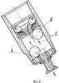
На фиг. 1 показан клапан в разрезе в конце операции продавки тампонажного раствора; на фиг. 2 - укрупненный вид на шаровой затвор в его нижнем положении; на фиг. 3 - клапан в разрезе по окончании продавки тампонажного раствора. In FIG. 1 shows a cross-sectional valve at the end of a grouting operation; in FIG. 2 - an enlarged view of the ball valve in its lower position; in FIG. 3 - sectional valve at the end of grouting grouting.
Предложенный обратный клапан для обсадных колонн состоит из корпуса 1 с размещенным в нем эластичным седлом 2 под шаровой затвор 3, ограничителя перемещения шарового затвора 4 с периферийными отверстиями 5, перекрываемыми кольцевой перегородкой 6, и центральным клапаном 7 для размещения дросселя (дросселирующей втулки) 8, подпружиненной пружиной 9 между ее съемным буртом 10 и кольцевой перегородкой 6. На верхнем торце ограничителя шарового затвора 4 закреплен соосно с ним ловитель шарового затвора 11, выполненный в виде патрубка 12 с канавкой на его внутренней поверхности 13 для размещения уплотнительного кольца 14. Высота патрубка 12 h больше диаметра шарового затвора, а расстояние l от седла до верхнего торца патрубка меньше диаметра шарового затвора (фиг. 1). The proposed check valve for casing strings consists of a housing 1 with an
Внутренний диаметр уплотнительного кольца 14 меньше диаметра шарового затвора 3. Нижняя стенка канавки 13 расположена в одной плоскости с плоскостью наибольшего сечения шарового затвора (фиг. 2). The inner diameter of the o-
Работает предлагаемый клапан обратный обсадных колонн следующим образом. The proposed casing check valve operates as follows.
Колонну с обратным клапаном спускают в скважину без шара 3. При этом буровой раствор заполняет колонну, поступая в нее из скважины через дросселирующую втулку 8. The casing with a non-return valve is lowered into the well without
Шар 3 бросают в колонну в процессе промывки скважины перед цементированием и доставляют его потоком жидкости к клапану. Далее шар 3 проскакивает через эластичное седло 2, попадает в ловитель 11, входит с натягом в уплотнительное кольцо 14 и занимает свое крайнее нижнее положение. При этом промывочная жидкость, а затем и тампонажный раствор обтекает верхний торец патрубка и направляется в периферийные отверстия 5, не воздействуя на шар, из-за образования неподвижного буфера между потоком и шаром.
По окончании цементирования обратный поток тампонажного раствора сначала закрывают отверстие 5 пластиной 6, а затем выталкивает шар 3 из ловителя 11 до посадки его непосредственно на седло 2, после чего обратное движение тампонажного раствора из затрубного пространства в колонну прекращается (фиг. 3). At the end of cementing, the back flow of the cement slurry is first closed by the hole 5 with the plate 6, and then pushes the
Надежная работа предлагаемой конструкции клапана позволит сразу по окончании цементирования снять избыточное давление внутри колонны и демонтировать цементировочную головку. В условиях кустового бурения наклонных скважин буровой станок может быть передвинут на новую точку без задержки. Reliable operation of the proposed valve design will allow immediately after cementing to remove excess pressure inside the column and dismantle the cementing head. In cluster drilling of deviated wells, the drilling rig can be moved to a new point without delay.
Экономическая эффективность применения предложенного устройства обусловлена экономией дополнительных затрат, связанных с простоем бурового станка из-за отказа в работе обратного клапана. The economic efficiency of the proposed device is due to the saving of additional costs associated with downtime of the drilling rig due to a failure in the check valve.
Предложенная конструкция клапана, предотвращающая износ шарового затвора на промежуточных операциях до включения его в работу в нужный момент, может найти эффективное практическое использование в качестве обратного клапана для бурильных колонн с целью повышения его долговечности и надежности работы. The proposed valve design, which prevents wear of the ball valve in intermediate operations until it is put into operation at the right time, can find effective practical use as a check valve for drill strings in order to increase its durability and reliability.
Claims (1)
Translated fromRussianPriority Applications (1)
| Application Number | Priority Date | Filing Date | Title |
|---|---|---|---|
| RU96100720/03ARU2115798C1 (en) | 1996-01-05 | 1996-01-05 | Non-return valve for casing strings |
Applications Claiming Priority (1)
| Application Number | Priority Date | Filing Date | Title |
|---|---|---|---|
| RU96100720/03ARU2115798C1 (en) | 1996-01-05 | 1996-01-05 | Non-return valve for casing strings |
Publications (2)
| Publication Number | Publication Date |
|---|---|
| RU96100720A RU96100720A (en) | 1998-03-27 |
| RU2115798C1true RU2115798C1 (en) | 1998-07-20 |
Family
ID=20175759
Family Applications (1)
| Application Number | Title | Priority Date | Filing Date |
|---|---|---|---|
| RU96100720/03ARU2115798C1 (en) | 1996-01-05 | 1996-01-05 | Non-return valve for casing strings |
Country Status (1)
| Country | Link |
|---|---|
| RU (1) | RU2115798C1 (en) |
Cited By (6)
| Publication number | Priority date | Publication date | Assignee | Title |
|---|---|---|---|---|
| RU2188931C1 (en)* | 2002-01-22 | 2002-09-10 | Айгунян Валерий Вагинакович | Device for plugging the casting string |
| RU2215125C2 (en)* | 2001-04-05 | 2003-10-27 | Мильштейн Всеволод Михайлович | Check valve for controlled directional and horizontal wells |
| RU2247277C2 (en)* | 2003-05-19 | 2005-02-27 | Дочернее открытое акционерное общество МЗ "Нефтетерммаш" | Ball valve |
| RU2265714C2 (en)* | 2003-02-13 | 2005-12-10 | ООО "Нефтегазмаш-Технологии" | Check valve for casing pipe |
| RU2612167C1 (en)* | 2015-09-14 | 2017-03-02 | Закрытое акционерное общество "ПРОММАШСЕРВИС" | Valve for casing strings |
| RU2612771C1 (en)* | 2016-04-06 | 2017-03-13 | Закрытое акционерное общество "ПРОММАШСЕРВИС" | Return valve for casing strings |
Citations (2)
| Publication number | Priority date | Publication date | Assignee | Title |
|---|---|---|---|---|
| SU419615A1 (en)* | 1971-06-18 | 1974-03-15 | CAMERA VALVE | |
| SU1218078A1 (en)* | 1984-04-12 | 1986-03-15 | Всесоюзный научно-исследовательский институт по креплению скважин и буровым растворам | Check valve for casings |
- 1996
- 1996-01-05RURU96100720/03Apatent/RU2115798C1/ennot_activeIP Right Cessation
Patent Citations (2)
| Publication number | Priority date | Publication date | Assignee | Title |
|---|---|---|---|---|
| SU419615A1 (en)* | 1971-06-18 | 1974-03-15 | CAMERA VALVE | |
| SU1218078A1 (en)* | 1984-04-12 | 1986-03-15 | Всесоюзный научно-исследовательский институт по креплению скважин и буровым растворам | Check valve for casings |
Cited By (6)
| Publication number | Priority date | Publication date | Assignee | Title |
|---|---|---|---|---|
| RU2215125C2 (en)* | 2001-04-05 | 2003-10-27 | Мильштейн Всеволод Михайлович | Check valve for controlled directional and horizontal wells |
| RU2188931C1 (en)* | 2002-01-22 | 2002-09-10 | Айгунян Валерий Вагинакович | Device for plugging the casting string |
| RU2265714C2 (en)* | 2003-02-13 | 2005-12-10 | ООО "Нефтегазмаш-Технологии" | Check valve for casing pipe |
| RU2247277C2 (en)* | 2003-05-19 | 2005-02-27 | Дочернее открытое акционерное общество МЗ "Нефтетерммаш" | Ball valve |
| RU2612167C1 (en)* | 2015-09-14 | 2017-03-02 | Закрытое акционерное общество "ПРОММАШСЕРВИС" | Valve for casing strings |
| RU2612771C1 (en)* | 2016-04-06 | 2017-03-13 | Закрытое акционерное общество "ПРОММАШСЕРВИС" | Return valve for casing strings |
Similar Documents
| Publication | Publication Date | Title |
|---|---|---|
| US6923255B2 (en) | Activating ball assembly for use with a by-pass tool in a drill string | |
| CA2632182C (en) | Apparatus for autofill deactivation of float equipment and method of reverse cementing | |
| US5494107A (en) | Reverse cementing system and method | |
| RU2147336C1 (en) | Device for hydraulic-pulse treatment of bed | |
| US3537518A (en) | Safety drill pipe float valve with heat responsive shut off sleeve | |
| US4341272A (en) | Method for freeing stuck drill pipe | |
| RU2115798C1 (en) | Non-return valve for casing strings | |
| RU2303116C1 (en) | All-purpose valve for downhole motor | |
| US3040710A (en) | Check valve | |
| US4286664A (en) | Positive seal float collar | |
| US3379261A (en) | Percussion tool | |
| RU2190083C1 (en) | Straightway valve-shutoff device | |
| RU2224087C2 (en) | Gate-type well valve | |
| RU2250355C1 (en) | Casing strings valve | |
| RU2446271C2 (en) | Hydraulic impact device | |
| SU1765367A1 (en) | Casing stepped cementation sleeve | |
| RU2326231C1 (en) | Flap for casing string | |
| SU1661375A1 (en) | Casing float valve | |
| SU945386A1 (en) | Borehole shutoff valve | |
| RU2224088C2 (en) | Return valve for casing string | |
| RU2233963C2 (en) | Downhole valve | |
| RU2148704C1 (en) | Discharge valve | |
| SU651120A1 (en) | Well closure device | |
| RU2223436C2 (en) | Check valve | |
| RU57805U1 (en) | CASING LOWER EQUIPMENT |
Legal Events
| Date | Code | Title | Description |
|---|---|---|---|
| MM4A | The patent is invalid due to non-payment of fees | Effective date:20050106 |