RU2111532C1 - Communication system - Google Patents
Communication systemDownload PDFInfo
- Publication number
- RU2111532C1 RU2111532C1SU5010326ASU5010326ARU2111532C1RU 2111532 C1RU2111532 C1RU 2111532C1SU 5010326 ASU5010326 ASU 5010326ASU 5010326 ASU5010326 ASU 5010326ARU 2111532 C1RU2111532 C1RU 2111532C1
- Authority
- RU
- Russia
- Prior art keywords
- output
- input
- port
- control
- matrix
- Prior art date
Links
Images


Classifications
- G—PHYSICS
- G06—COMPUTING OR CALCULATING; COUNTING
- G06F—ELECTRIC DIGITAL DATA PROCESSING
- G06F15/00—Digital computers in general; Data processing equipment in general
- G06F15/16—Combinations of two or more digital computers each having at least an arithmetic unit, a program unit and a register, e.g. for a simultaneous processing of several programs
- G06F15/163—Interprocessor communication
- G06F15/173—Interprocessor communication using an interconnection network, e.g. matrix, shuffle, pyramid, star, snowflake
- G06F15/17356—Indirect interconnection networks
- G06F15/17368—Indirect interconnection networks non hierarchical topologies
- G06F15/17375—One dimensional, e.g. linear array, ring
- H—ELECTRICITY
- H04—ELECTRIC COMMUNICATION TECHNIQUE
- H04L—TRANSMISSION OF DIGITAL INFORMATION, e.g. TELEGRAPHIC COMMUNICATION
- H04L12/00—Data switching networks
- H—ELECTRICITY
- H04—ELECTRIC COMMUNICATION TECHNIQUE
- H04L—TRANSMISSION OF DIGITAL INFORMATION, e.g. TELEGRAPHIC COMMUNICATION
- H04L49/00—Packet switching elements
- H04L49/10—Packet switching elements characterised by the switching fabric construction
- H04L49/101—Packet switching elements characterised by the switching fabric construction using crossbar or matrix
Landscapes
- Engineering & Computer Science (AREA)
- Physics & Mathematics (AREA)
- Signal Processing (AREA)
- Computer Hardware Design (AREA)
- Theoretical Computer Science (AREA)
- Computer Networks & Wireless Communication (AREA)
- Mathematical Physics (AREA)
- Software Systems (AREA)
- General Engineering & Computer Science (AREA)
- General Physics & Mathematics (AREA)
- Data Exchanges In Wide-Area Networks (AREA)
- Small-Scale Networks (AREA)
- Multi Processors (AREA)
- Computer And Data Communications (AREA)
Abstract
Description
Translated fromRussianИзобретение касается передачи информации, а более конкретно - одновременной передачи информации между разными системами обработки данных, используя матричный коммутатор. The invention relates to the transmission of information, and more specifically, the simultaneous transmission of information between different data processing systems using a matrix switch.
Системы обработки данных требуют передачи информации между компонентами системы обработки данных. Имеется несколько способов для осуществления передачи информации в системах обработки данных. Один способ, который является очень выгодным, состоит в одновременной передаче информации между несколькими элементами системы обработки данных путем использования матричного коммутатора. Пример матричного коммутатора приведен в патенте США N 4630045 под названием "Контроллер для матричного коммутатора". Матричный коммутатор обеспечивает одновременные коммутационные соединения между парами элементов системы обработки данных, так что несколько этих соединенных пар могут производить обмен информацией в одно и то же время через коммутатор. Матричный коммутатор в патенте США N 4630045 показывает реализацию матричного коммутатора предшествующего уровня техники, в результате чего порты матричного коммутатора, которые соединены с элементами обработки данных, соединены с коммутационной матрицей и централизованной управляющей схемой, которая управляет операциями портов и их соединениями через саму коммутационную матрицу. Data processing systems require the transfer of information between components of a data processing system. There are several methods for transmitting information in data processing systems. One way, which is very advantageous, is to simultaneously transfer information between several elements of a data processing system by using a matrix switch. An example of a matrix switcher is given in US Pat. No. 4,630,045, entitled "Controller for a Matrix Switcher." The matrix switch provides simultaneous switching connections between pairs of data processing system elements, so that several of these connected pairs can exchange information at the same time through the switch. The matrix switcher in U.S. Patent No. 4,630,045 shows an implementation of the prior art matrix switcher, whereby the ports of the matrix switcher, which are connected to the data processing elements, are connected to a switching matrix and a centralized control circuit that controls the port operations and their connections through the switching matrix itself.
Патент США N 4814762, озаглавленный "Управление схемой соединения треугольником матричного коммутатора" показывает другой вариант реализации матричного коммутатора, где фактические коммуникации между портами матричного коммутатора содержатся в схеме соединения треугольником. Согласно техническим решениями этого патента, когда порт пытается получить доступ к другому порту, он посылает сообщение запроса в отношении указанного соединения по схеме соединения треугольником. Эта коммуникация происходит снаружи самого матричного коммутатора. Настоящее изобретение направлено на создание коммуникаций через матричный коммутатор и тем самым образует коммуникацию внутри полосы частот не только для передачи данных, но и также для указания требуемых соединений между компонентами. US Pat. No. 4,814,762, entitled "Managing a Triangle Connection Pattern of a Matrix Switcher", shows another embodiment of a matrix switcher, where the actual communications between the ports of the matrix switcher are contained in a triangle connection pattern. According to the technical solutions of this patent, when a port tries to access another port, it sends a request message regarding the specified connection using the triangle connection scheme. This communication takes place outside the matrix switcher itself. The present invention is directed to the creation of communications through a matrix switcher and thereby forms a communication within the frequency band not only for data transmission, but also for indicating the required connections between components.
Патент США N 4752777, озаглавленный "Схема соединения треугольником матричного коммутатора", является продолжением предшествующей заявки на патент США N 4814762 и описывает схему соединения треугольником для управления портами матричного коммутатора. US Pat. No. 4,752,777, entitled "Matrix Switch Triangle Connection Diagram", is a continuation of the previous US Patent Application No. 4,814,762 and describes a triangle connection diagram for controlling matrix switch ports.
В патенте США N 4695999 описывается многополосковый матричный коммутатор и управление портами, соединенными с матричным коммутатором. US Pat. No. 4,695,999 describes a multi-strip matrix switcher and control of ports connected to the matrix switcher.
Патент США N 4845722, озаглавленный "Компьютерный соединитель с использованием матричного коммутатора", описывает систему соединителя для соединения компонентов, которая включает в себя централизованную логическую схему коммутации для управления коммутационной матрицей. US Pat. No. 4,845,722, entitled “Computer Connector Using a Matrix Switcher,” describes a connector system for connecting components, which includes a centralized switching logic for controlling a switching matrix.
Патент США N 4580011, озаглавленный "Распределительная обрабатывающая телефонная коммутационная система", описывает коммутационную систему, имеющую централизованный контроллер, который принимает управляющие сигналы от линейных соединителей, чтобы направить соединение через коммутационную матрицу. US Pat. No. 4,580011, entitled "Distribution Processing Telephone Switching System", describes a switching system having a centralized controller that receives control signals from line connectors to route a connection through a switching matrix.
В работе (Бюллетень технических решений IBM, том 28, N 2, июль 1985 г., с. 510-512), озаглавленной "Коммутатор схемы с быстрым установочным временем с распределенным управлением", описывается система управления коммутационной матрицей, имеющей порты, которые сообщаются с центральным управляющим контроллером для управления работой матричного коммутатора. The paper (IBM Technical Solutions Bulletin, Volume 28, No. 2, July 1985, pp. 510-512), entitled "Distributed Control Fast Switching Time Circuit Switch", describes a patch matrix control system having ports that communicate with a central control controller to control the operation of the matrix switch.
В работе (Бюллетень технических решений IBM, том 29, N 3, август 1986 г. , с. 1356-1360, озаглавленной "Динамически реконфигурируемый интегральный коммутатор", описывается реконфигурируемый коммутатор, предназначенный поддерживать многие схемы разных типов. Эта конфигурация включает в себя контроллер коммутатора, который управляет доступом портов к коммутатору. The IBM Technical Bulletin, Volume 29, No. 3, August 1986, pp. 1356-1360, entitled "Dynamically Configurable Integrated Switch", describes a reconfigurable switch designed to support many different types of circuits. This configuration includes a controller a switch that controls port access to the switch.
В работе (Бюллетень технических решений IBM, том 32, N 1, июнь 1989 г, с. , 427-433), озаглавленной "Механизм управления в отношении контроллера коммуникации пакетной шины", описывается контроллер для пакетной шины. Пакетная шина разрешает только одну передачу информации за один раз в противоположность матричному коммутатору, который разрешает одновременные и непрерывные передачи информации между сообщающимися парами элементов системы. The paper (IBM Technical Solutions Bulletin,
В работе (Бюллетень технических решений IBM, том 20, N 2, июль 1977 г., с. 816-817), озаглавленной "Матричный коммутатор для АТС", описывается матричный коммутатор с контроллером, который регулирует доступ портов через матричный коммутатор. The paper (IBM Technical Solutions Bulletin, Volume 20,
В работе (Бюллетень технических решений IBM, том 29, N 4, сентябрь 1986 г., с. 1769-1771), озаглавленной "Разрешающая способность гонки в соединении трассы любого с любым с временным разделением в коммутаторе с пространственным разделением", описывается коммутатор, обеспечивающий возможность "пакетно-образной" коммуникации. Как сказано ранее, пакетная передача производит только одну пару связи за один раз. In the work (IBM Technical Solutions Bulletin, Volume 29, No. 4, September 1986, pp. 1769-1771), entitled "Race Resolution in Connecting Any and Any Trail with a Time Division in a Spatial Switch," describes the switch, providing the possibility of "packet-shaped" communication. As stated earlier, packet transmission produces only one pair of communications at a time.
В работе (Бюллетень технических решений IBM, том 27, N 4B, сентябрь 1984 г. , с. 2704-2708), озаглавленной "Переменной конфигурации гибридная пространственная и пакетная коммутационная сеть", описывается трехуровневое коммутационное устройство для сети пакетной передачи, используя центральное управление для установления соединений трассы". The paper (IBM Technical Solutions Bulletin, Volume 27, No. 4B, September 1984, pp. 2704-2708), entitled "Variable Configuration Hybrid Spatial and Packet Switching Networks," describes a three-level switching device for a packet network using central control to establish trace connections. "
В работе (Бюллетень технических решений IBM, том 24, N 7A, декабрь 1981 г. , с. 3352-3356), озаглавленной "Многотрассовый матричный коммутатор с адаптором канала с каналом", описывается с централизованным управлением коммутационное устройство, обеспечивающее межпроцессорные связи через каналы входа/выхода. The paper (IBM Technical Solutions Bulletin, Volume 24, N 7A, December 1981, pp. 3352-3356), entitled "Multi-track Matrix Switcher with Channel Adapter with Channel," describes a centralized control switching device that provides interprocess communication over channels entry / exit.
В работе (Бюллетень технических решений IBM, том 28, N 8, январь 1986 г. , с. 3272-3273), озаглавленной "Параллельная архитектура процессора для управления многочисленными независимыми телекоммуникационными узлами коммутации", описывается телекоммуникационная система, использующая распределенные параллельные процессоры для управления сетью распределения. The paper (IBM Technical Solutions Bulletin, Volume 28, No. 8, January 1986, pp. 3272-3273), entitled "Parallel processor architecture for controlling multiple independent telecommunication switching nodes", describes a telecommunication system that uses distributed parallel processors to control distribution network.
Как сказано ранее, были предложены другие способы передачи данных в предшествующем уровне техники. Один такой способ использует информационную шину, дающую возможность пропускать только одно сообщение за один раз. Пример этого способа шины приведен в патенте США N 4586175, озаглавленном "Способ функционирования пакетной шины для передачи асинхронных и псевдосинхронных сигналов". Этот патент описывает шину, управляемую двумя контрольными шинами. Патент США N 4363093, озаглавленный "Процессорная межкоммуникационная система", описывает межкоммуникационную систему между процессорами локальной зональной сети, по которой только одно сообщение может передаваться за один раз. Патент США N 4821170, озаглавленный "Система входа/выхода для мультиплексоров, также описывает систему, предусматривающую две шины системы, но не использующую коммутатор для облегчения внутрисистемной связи (связи между компонентами системы). As said earlier, other methods for transmitting data in the prior art have been proposed. One such method uses an information bus, allowing only one message to be skipped at a time. An example of this bus method is given in US Pat. No. 4,586,175, entitled "Method of Functioning a Packet Bus for Transferring Asynchronous and Pseudo-Synchronous Signals." This patent describes a tire driven by two control buses. US Pat. No. 4,363,093, entitled "Processor Intercommunication System", describes an intercommunication system between processors in a local area network through which only one message can be transmitted at a time. US Pat. No. 4,821,170, entitled "I / O System for Multiplexers, also describes a system that provides two system buses but does not use a switch to facilitate intra-system communication (communication between system components).
Другие примеры коммутации типа шины приведены в патенте США N 4704606, озаглавленном "Переменной длительности пакетная коммутационная система". Этот пакет описывает пакетную коммутационную систему для пакетов переменной длительности. Патент США N 4631534, озаглавленный "Распределенная пакетная коммутационная система", описывает пакетную коммутационную систему, где каждый порт включает в себя интеллект (логическую схему) для образования адресов порта назначения и станции в пакетах. Патент США N 4630258, озаглавленный "Коммутационный узел памяти 11 х M с пакетами коммутируемыми мультипортами и способ обработки", описывает пакетную коммутационную систему, использующую 11 х M коммутатор от 11 входных портов, соединяемых с M выходных портов. Коммутатор имеет центральное управление. Other examples of bus type switching are described in US Pat. No. 4,704,606, entitled "Variable Duration Packet Switching System". This packet describes a packet switching system for variable duration packets. US Pat. No. 4,631,534, entitled "Distributed Packet Switching System", describes a packet switching system where each port includes intelligence (logic) to form the destination port and station addresses in packets. US Pat. No. 4,630,258, entitled "11 x M Switching Node Packet with Switched Multiport Packets and Processing Method", describes a packet switching system using an 11 x M switch from 11 input ports connected to M output ports. The switch has central control.
Патент США N 4773069, озаглавленный "Надежная трассируемая древовидная (разветвленная) схема", описывает схему передачи данных, включающую в себя модемы и имеющую по крайней мере два контроллера, соединенные с модемами. US Patent No. 4,773,069, entitled "Reliable Traceable Tree (Branched) Scheme", describes a data transmission scheme including modems and having at least two controllers connected to modems.
Другие технические решения в области общей коммутации, иллюстрирующие коммутатор. В работе (Бюллетень технических решений IBM, том 25, N 7A, декабрь 1982 г., с. 3578-3582), озаглавленной "Система обработки и управления базой данных", описывается главный (ведущий) процессор, сообщающийся с множеством сателлитных (ретранслирующих) процессоров через коммутационную матрицу данных. Коммутатор и работа ретрансляторов управляются главным процессором. В работе (Бюллетень технических решений IBM, том 29, N 7, декабрь 1985 г., с. 3070-3072), озаглавленной "Вращающийся коммутатор", описывается вращающийся коммутатор. В работе (Бюллетень технических решений IBM, том 30, N1, июнь 1987 г., с. 403-405), озаглавленной "Архитектура динамического временного распределения щелей для цифрового телефонного коммутатора", описывается ординарный порт, обеспечивающий доступ к цифровой телефонной коммутационной системе. В работе (Бюллетень технических решений IBM, том 11, N 10, март 1969 г., с. 1231-1232), озаглавленной "Соединение управляющих схем", описывается многократно избыточное коммутационное устройство для цифрового компьютера. Other technical solutions in the field of general switching, illustrating the switch. The work (IBM Technical Solutions Bulletin, Volume 25, N 7A, December 1982, pp. 3578-3582), entitled "Database Processing and Management System", describes the main (leading) processor communicating with a variety of satellite (relaying) processors through the switching data matrix. The switch and relay operation are controlled by the main processor. The paper (IBM Technical Solutions Bulletin, Volume 29, No. 7, December 1985, pp. 3070-3072), entitled “Rotary Switch”, describes a rotary switch. The paper (IBM Technical Solutions Bulletin,
Все вышеупомянутые прототипы описывают использование централизованного управления для коммутационной схемы. Цель настоящего изобретения состоит в создании распределенного управления по портам, соединенным с коммутатором, чтобы более эффективно регулировать соединения портов с коммутатором, и тем самым коммуникацию через коммутатор. All of the above prototypes describe the use of centralized control for a switching circuit. An object of the present invention is to provide distributed control over ports connected to a switch in order to more efficiently control port connections to the switch, and thereby communicate through the switch.
В соответствии с настоящим изобретением предусматривается коммуникационная сеть, которая включает в себя множество портов, каждый из которых соединен по крайней мере с одним элементом системы обработки данных. Предусмотрена шина, которая соединяет порты между собой. Предусмотрен матричный коммутатор, который соединен с портами и шиной, соединяющей порты. Матричный коммутатор создает возможность соединять коммутационные каналы между любыми двумя портами. Каждый из портов содержит управляющую логику, соединенную с шиной для связи с другими портами, и матричный коммутатор для регулирования установления коммуникационных каналов между портами. In accordance with the present invention, a communication network is provided that includes a plurality of ports, each of which is connected to at least one element of a data processing system. A bus is provided that connects the ports to each other. A matrix switcher is provided that is connected to the ports and a bus connecting the ports. The matrix switch provides the ability to connect switching channels between any two ports. Each of the ports contains control logic connected to the bus for communication with other ports, and a matrix switch for regulating the establishment of communication channels between the ports.
Вышеприведенные и другие цели, отличительные признаки и преимущества изобретения будут лучше поняты из нижеследующего подробного описания наилучшего варианта реализации изобретения со ссылкой на приведенные ниже чертежи. The above and other objects, features, and advantages of the invention will be better understood from the following detailed description of the best embodiment of the invention with reference to the drawings below.
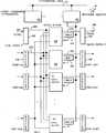
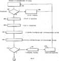
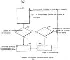
На фиг. 1 дана блок-схема, показывающая восемь систем, соединенных с первым матричным коммутатором, и одну, соединенную со вторым матричным коммутатором; на фиг. 2 - блок-схема, показывающая содержание матричного коммутатора; на фиг. 3 - блок-схема, показывающая содержание схемы портов матричного коммутатора; на фиг. 4 - блок-схема матричного коммутатора; на фиг. 5 - схема событий, показывающая события между портом A, портом B и матричным коммутатором при установке связи между портом A и портом B; на фиг. 6 - схема событий, показывающая разъединения между портом A и портом B; на фиг. 7 - блок-схема порядка действий, показывающая управление порта, когда коммуникационный фрейм принят от его канала связи ("фрейм" здесь и далее это служебное кодовое управляющее слово, представляющее собой информационный блок кодирования команд, используемых в общении между компонентами системы); на фиг. 8 - блок-схема порядка действий, показывающая управление порта, когда принят запрос от коммуникационной шины; на фиг. 9 - блок-схема порядка действий, показывающая окончание коммуникации портом; на фиг. 10 - блок-схема порядка действий, показывающая управление матричного коммутатора во время коммуникации порта с портом. In FIG. 1 is a block diagram showing eight systems connected to a first matrix switcher and one connected to a second matrix switcher; in FIG. 2 is a block diagram showing the contents of a matrix switcher; in FIG. 3 is a block diagram showing the contents of a port circuit of a matrix switcher; in FIG. 4 is a block diagram of a matrix switch; in FIG. 5 is an event diagram showing events between port A, port B and matrix switcher when communication is established between port A and port B; in FIG. 6 is an event diagram showing disconnections between port A and port B; in FIG. 7 is a flowchart showing port control when a communication frame is received from its communication channel (“frame” hereinafter is a service code control word, which is an information block for encoding instructions used in communication between system components); in FIG. 8 is a flowchart showing port control when a request is received from the communication bus; in FIG. 9 is a flowchart showing the end of communication by a port; in FIG. 10 is a flowchart showing control of the matrix switch during port-to-port communication.
На фиг. 1 показана блок-схема коммуникационной системы, которая включает в себя несколько систем 14, 16, 18, 20, 22, 24, 26 и 28, каждая из которых соединена с матричным коммутатором 10. Каждая из этих систем, такая как система 14, соединена с матричным коммутатором 10 через порт 8. Следует отметить, что каждая система, такая как система 24, может быть альтернативно соединена с дополнительными матричными коммутаторами (таким как матричный коммутатор 12) для резервной возможности или возможности соединения. В предпочтительном варианте реализации система 14 и система 24 являются системой RISC/6000 - автоматизированными рабочими местами (APM), которые соединены посредством последовательного световодного канала с матричным коммутатором 10. В этом предпочитаемом варианте реализации каждый компонент системы RISC/6000 может включать в себя четыре порта для реализации соединений последовательной связи. Пример протокола, используемого с соединителем последовательной связи, представляет ESCON (соединение предпринимательской системы для последовательного канала входа/выхода предпринимательской системы IBM 3090). Должно быть понято, что в этом предпочитаемом варианте реализации, когда система должна соединяться с другой системой для предоставления информации другой системе, вся информация подается через этот световодный канал последовательной связи. Исходная система будет посылать фрейм информации до 32 байтов для первоначального установления связи с принимающей системой. После того, как первый фрейм был послан и принят, установление соединения через матричный коммутатор 10 производится, и это соединение поддерживается, так что исходная система может постоянно пропускать дополнительные фреймы информации на принимающую систему, пока не будет послан фрейм о разъединении, чтобы известить принимающую систему и коммутатор 10, что связь прекращается (разъединяется). В предпочитаемом варианте реализации матричный коммутатор является коммутатором 11 х 11, поддерживающим 11 х 11 портов для обеспечения одновременной коммуникации между соединенными портами и системами, соединенными с портами. In FIG. 1 is a block diagram of a communication system that includes
На фиг. 2 представлена блок-схема матричного коммутатора данных 10. В предпочитаемом варианте реализации используется коммутатор 16 х 16. Только для цели описания показано восемь портов из 16. Каждый порт 30 соединен с арбитражной шиной портов 50, управляющей шиной портов 52 и линиями передачи данных (такими как линии 54 и 55 для портов 30 и 42 соответственно). Каждый из портов соединен через эти линии данных с матричным коммутатором 16 х 16. Матричный коммутатор 40 может быть готовым (выпускаемым промышленностью) изделием, таким как ГИГАБИТ Ложик 100051, который образует соединение точек пересечения между портами (за исключением Ложик 600 и фиксации адресов 602, фиг. 4). In FIG. 2 is a block diagram of a matrix data switch 10. In a preferred embodiment, a 16 x 16 switch is used. Eight ports of 16 are shown for description purposes only. Each
В предпочтительном варианте реализации каждый порт производит оптико-электрическое преобразование, чтобы информация пропускалась электрически между портами через матрицу 40 16 х 16. Первоначально порт, такой как 30, может попытаться соединиться с другим портом, таким как порт 32. Сначала порт 30 запросит арбитраж. Иначе говоря, порт 30 запросит разрешение по арбитражной шине 50 в арбитре шины 38. После получения разрешения по управляющей шине 52 будет передан запрос о соединении на порт 32. Затем происходит прием состояния. На фиг. 2 приведен пример, когда порт 32 пытается соединиться с портом 30 путем посылки запроса, символически обозначенного стрелкой 58. Порт 30 посылает сигнал занятости (занято), обозначенный символически пунктирной стрелкой 56, обратно на порт 32, отклоняя запрос о передаче. Следует отметить, что во время этой первоначальной попытки в соединении порта с портом матрица 16 х 16 не имела доступа. Это возможно благодаря наличию управления коммутационного устройства, которое (управление) распределено между портами. Иначе говоря, только после приема подтверждения, что передача данных может иметь место, коммутатор 40 включается в соединение между портами. In a preferred embodiment, each port performs optoelectric conversion so that information is passed electrically between the ports through a 40 x 16 matrix. Initially, a port, such as 30, may try to connect to another port, such as
Матричный коммутатор 40 соединен с управляющей шиной 52. Это может возбуждать матричный коммутатор 40 для ответа на команды, направленные ему. В предпочитаемом варианте реализации только команды, которые направлены матричному коммутатору 40, являются командами диагностического характера. Во время нормального функционирования матричный коммутатор 40 просто контролирует управляющую шину 52 и управляющую коммуникацию между портами, чтобы определить когда соединения должны быть произведены или прекращены. Когда соединения произведены, линии, такие как 54, соединены с линиями, такими как 55, для возможности передачи данных между портами, такими как порт 30 и порт 42, без запроса явных команд для коммутаторов от портов или другого управляющего устройства. The
Операция отсоединения производится матричным коммутатором 40 без команды со стороны портов. Матричный коммутатор 40 производит перехват (подслушивание) по командной шине 52, чтобы определить, когда разъединение должно быть произведено путем изучения команд о разъединении на управляющей шине 52. Когда фрейм об окончании связи послан по одной системе другой, матричный коммутатор 40 путем контроля управляющей шины 52 автоматически определяет, какое соединение должно быть разъединено, тем самым экономя время в том, что не запрашивается отдельный протокол команды, чтобы сказать матричному коммутатору произвести разъединение. Это является важным, потому что операция разъединения производит на базе высокого приоритета, так как дальнейшее соединение с любым из портов может быть происходит только в случае, когда происходит это разъединение. The disconnect operation is performed by the
На фиг. 3 представлена блок-схема логики, содержащейся в каждом порте, таком как порт 30. Основная машина управления состоянием и машина состояния соединить/занято 78 управляет функционированием логики порта. Логика состояния 78 соединена с прерывающим управляющим устройством 82, которое производит прерывание в случае условий ошибок на и от управляющей шины 52. Логика состояния 78 далее соединена с логикой 88 квитирования установления связи. Функционирование логики квитирования установления связи является типом, который описан в Бюллетене технических решений IBM, том 32, N 6A, ноябрь 1989, с. 21-22, в работе, озаглавленной "Способ оценки динамических трасс данных в коммутационном блоке данных". Когда фрейм сначала принят от системы, он принимается по шине 598, где первоначально фиксируется символ, в момент времени в принимающем регистре 102. Содержание этого регистра затем загружается в буфер 104 соединение/синхронизации, где логика управления записью или логика управления считыванием 90 и 92 соответственно с логикой состояния 78 определяют, будет ли буфер 104 действовать как пропускающий первый входящий/первый выходящий буфер или накапливающий буфер. Управление записью 92 определяет, когда в буфере 104 данные должны быть записаны. Логика управления считыванием 90 определяет, с какого мета в буфере 104 должен считываться следующий символ. Логика 106 декодирования и определения ошибки также соединена с логикой состояния 78, чтобы обозначить любое условие ошибки. Если фрейм должен быть пропущен на другой порт, запрос о соединении пропускается по управляющей шине. Как сказано ранее, арбитр посылает запрос арбитру шины 38 по шине 50 через интерфейс 100 арбитражной и управляющей шин. После разрешения машина состояния порта 78 посылает запрос о соединении и оценивает состояние, принятое по управляющей шине 52 от порта, предполагаемого для соединения. Если соединяемый порт не занят, тогда соединение устанавливается автоматически матрицей 40 и данные из буфера соединения/синхронизации 104 пропускаются через регистр 108 по линии данных 54B на матричный коммутатор. Принимающий мультиплексор 94 определяет загружены ли данные из линии 59B или логики квитирования установления связи 88 в регистр 108. Аналогичным образом данные, принимаемые от матричного коммутатора по линии 54A, проходят через регистр 80 через совмещенную логическую схему 76, который предотвращает проход кодовых ошибок блока через передающий мультиплексор 72 на передающий регистр 70 по шине 59A. Следует отметить, что в передающей стороне логика 74 занятости и отклонения, а также логика 84 декодирования и детектирования ошибки предусмотрены для условий ошибки. Логика 74 занятости/отклонения определяет, когда принята индикация о занятости от управляющей шины 52, и образует фрейм занятости по линии 59A. Буфер 96 фрейма предназначен для передачи ранее указанных фреймов, указывающих специфические условия ошибок. In FIG. 3 is a block diagram of the logic contained in each port, such as
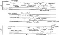
На фиг. 5 представлена схема событий, показывающая соединение между портом A и портом B. На фиг. 5 фрейм сначала принимается портом по шине (такой как 59B) в событии 120. В событии 122 логика порта изучает фрейм и определяет установление соединения, в событии 124 решает конфликт в отношении управляющей шины. Арбитр 38 шины принимает запрос о событии 126 и разрешает (предоставляет) запрос в событии 128. В это время логика порта A выдает запрос о соединении 130, который включает в себя соответствующие адреса портов, по управляющей шине 52, обозначенной под событием 132. Логика матрицы 600 (фиг. 4) наблюдает за этим запросом в событии 134 и фиксирует адреса портов, которые фиксированы в фиксаторах 602, тогда как логика порта B рассматривает этот запрос о событии 136. Логика порта B затем посылает ответ 142, который рассматривается логикой матрицы 600 в событии 140, по управляющей шине 52, как показано под событием 138. Этот ответ считывается логикой порта A в событии 144. В этом примере приводится последовательное соединение. Поэтому логика матрицы 600 загружает адрес порта из фиксаторов 602 в регистры, такие как 614 и 624, чтобы дать возможность схемам выборки данных 608 и 620 соединить внутреннюю шину 606 с внутренней шиной 622. Логика порта A тогда образует сигнал квитирования установления связи с портом B по шине матрицы, такой как 54A и 54B. Сначала происходят события 152 и 154 передачи квитирования установления связи из обоих портов, а затем из обоих портов квитирование установления связи в событиях 156 и 158 передается обратно на противоположные порты. Следует отметить, что логика матрицы автоматически соединяет порты A и B через матричный коммутатор 40. В конечном счете фрейм посылается в событии 160 по шине матрицы в событии 162 на матрицу в линии на порт B 166, где логика порта изучает фрейм в событии 164. Этот фрейм затем подается на выход линии связи на соединенное устройство в событии 168. In FIG. 5 is an event diagram showing the connection between port A and port B. FIG. 5, the frame is first received by the port on the bus (such as 59B) in
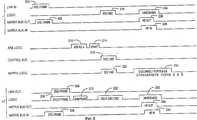
На фиг. 6 представлена схема событий, показывающая операцию разъединения. В этом примере порт A принимает фрейм о разъединении от своего соединенного устройства в событии 200. Это пропускается на выходную шину матрицы в событии 202. Это принимается портом B по входной шине матрицы в событии 208, где логика проверяет фрейм в событии 206, и фрейм распределяется по соединенным устройствам в событии 204. Логика в порте B затем определяет вопрос об арбитраже в отношении управляющей шины в событии 212 и принимается арбитром шины 38 в событии 210, что разрешает подать запрос в событии 214. Логика порта B затем посылает команду о разъединении в событии 222, которая рассматривается на управляющей шине в событии 218, посредством логики матрицы в событии 220 и логикой порта B в событии 216. Затем квитирование установления связи проводится через управляющую шину в событии 232 и 224 портами B и A соответственно, через входную и выходную линии матрицы для соответствующих портов в событиях 226, 228, 234 и 236 соответственно. Важное событие состоит в том, когда логика матрицы 40 автоматически отсоединяет порты A и B в событии 230 путем перехвата на управляющей шине и изучения команды о разъединении, затем посланную. In FIG. 6 is an event diagram showing a disconnect operation. In this example, port A receives a disconnect frame from its connected device in
Должно быть понятно специалистам в данной области техники, что путем перехвата по шине, чтобы рассмотреть команды о разъединении, дальнейших циклов шин не требуется для управления коммутатором, даже если коммутатор работает с тем, чтобы поддерживать автономные отношения между портами. It should be understood by those skilled in the art that by intercepting on a bus to consider disconnecting commands, further bus cycles are not required to control the switch, even if the switch is operating in order to maintain autonomous relationships between the ports.
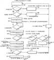
На фиг. 7 представлена блок-схема порядка действий, показывающая логику состояния 78 порта, когда она принимает фрейм. В блоке 300 фрейм принимается от устройства, соединенного со стороной связи порта. Логика сначала определяет, относится ли фрейм к существующему соединению. Это относится к случаю, когда прежний фрейм установил соединение, и этот существующий фрейм просто является одним из фреймов в последовательности фреймов, который пропускается через существующее соединение. На стадии 304 фрейм пропускается через существующее соединение по шине матрицы на матричный коммутатор. Управляющая логика затем возвращается к стадии 300 в ожидании следующего фрейма. Однако на стадии 302 соединение не было ранее установлено, управляющая логика определяет, полон ли буфер 104. Если да, фрейм игнорируется на стадии 308, и управляющая логика возвращается к ожиданию следующего фрейма. Если буфер фреймов не был заполнен, фрейм помещается в буфер на стадии 310, и управляющая логика решает конфликт в отношении управляющей шины на стадии 312. На стадии 314 логика ждет получения разрешения. В это время она приступает к выдаче запроса о соединении на стадии 318. На стадии 320 управляющая логика считывает записанный ответ порта. Ответ изучается на стадии 324 для определения, занят ли он или нет (стадия 326), в это время подается сообщение о занятости или, если порт указывает, что у него сбой (стадия 328), в этот момент посылается сообщение о сбое на стадии 334. Возвращение к стадии 324, если ответ успешный, порт маркирован как соединенный на стадии 330, и отправление квитирования об установлении связи начинается на стадии 336 через матрицу. Когда принимаемое квитирование установления связи принято на стадии 338, оно изучается на стадии 340. Если оно не в порядке, выдается сообщение об ошибке на стадии 342, и в это время буфер 104 очищается на стадии 316. Возвращение к стадии 340, если квитирование установления связи завершено успешно, фрейм посылается на матричный коммутатор 40 на стадии 324, и логика приступает к узлу A, показанному на фиг. 9 ( о чем будет сказано ниже). In FIG. 7 is a flowchart showing the state logic of
На фиг. 8 блок-схема порядка действий показывает функционирование управляющей логики порта, когда запрос принят от управляющей шины. Это происходит на стадии 400. В это время порт определяет будет или нет он соединен на стадии 402. Если да, порт отвечает на стадии 404 сигналом занято. Если нет, на стадии 406 порт отвечает, что он может произвести соединение. На стадии 408 порт запоминает индикацию, что он соединен, и на стадии 410 производит квитирование об установлении связи. Ответ о квитировании установления связи принимается на стадии 412 и изучается на стадии 414, чтобы определить, в порядке ли оно. Если нет, тогда на стадии 416 посылается сообщение об ошибке, и порт маркирует себя как отсоединенный на стадии 418, возвращаясь к стадии 400. Если, однако, на стадии 414 ответ о квитировании установления связи в порядке, тогда управляющая логика приступает к узлу A. In FIG. 8, a flowchart shows the operation of the control logic of the port when a request is received from the control bus. This occurs at
Узел A показан на фиг. 9 как соединяющий логику на фиг. 5 и 7 с каналом связи. Фреймы могут также посылаться от канала связи на матрицу, если это необходимо. На стадии 424 логика порта определяет, принят ли фрейм о разъединении от матричного коммутатора. Если нет, тогда логика порта определяет на стадии 426, принята ли команда о разъединении от управляющей шины. Если нет, тогда логика порта возвращается к стадии 420, чтобы продолжать посылать фреймы. Возвращение к стадии 424, если фрейм о разъединении был получен через матричный коммутатор, и затем на стадии 428 происходит выдача команды о разъединении по управляющей шине. Порт затем маркируется как отсоединенный на стадии 430. Аналогичным образом на стадии 426, если команда об отсоединении принята от управляющей шины, порт маркируется отсоединенным на стадии 430. Node A is shown in FIG. 9 as connecting logic in FIG. 5 and 7 with a communication channel. Frames can also be sent from the communication channel to the matrix, if necessary. At 424, the port logic determines whether a disconnect frame is received from the matrix switch. If not, then the port logic determines at 426 whether a disconnect command has been received from the control bus. If not, then the port logic returns to step 420 to continue to send frames. Returning to step 424 if the disconnect frame was received through the matrix switcher, and then, at
На фиг. 10 блок-схема порядка действий показывает управляющую логику матричного коммутатора 40. Следует отметить, что матричный коммутатор 40 является исполнительным устройством, которое перехватывает по управляющей шине и управляет соответственно соединениями коммутатора. На стадии 500 управляющая логика коммутатора определяет, послана ли команда по управляющей шине. Если нет, она продолжает ждать. Если команда есть, тогда адреса портов фиксируются на стадии 502. На стадии 504 команда изучается, чтобы определить, является ли это командой о соединении. Если да, на стадии 506 ответ порта контролируется и проверяется. Если ответ в порядке на стадии 508, тогда соединение шины между портами происходит на стадии 504. Аналогичным образом, на стадии 510 команда изучается, чтобы определить, является ли это командой о разъединении, и если да, тогда соединения порта разъединяются на стадии 512. In FIG. 10, the flowchart shows the control logic of the
Специалисту в этой области техники должно быть понятным, что логика перехвата матричного коммутатора может также использоваться для управления иными функциями, чем просто соединение или разъединение устройств. Например, логика перехвата матричного коммутатора может использоваться для определения, когда произошло указанное событие, путем изучения информации, связанной с соединением двух портов, и для контроля операции автономных устройств, таких как предотвращение двух последовательных соединений с одним и тем же портом, или операции разъединения с несоединенным портом. One skilled in the art will appreciate that the intercept logic of a matrix switcher can also be used to control functions other than simply connecting or disconnecting devices. For example, the matrix switch interception logic can be used to determine when a specified event occurred, by examining information related to the connection of two ports, and to monitor the operation of stand-alone devices, such as preventing two consecutive connections to the same port, or disconnecting operations from unconnected port.
Хотя это изобретение описано со ссылкой на показанный вариант реализации, оно не предназначено толковаться в ограничительном смысле. Разные модификации показанного варианта реализации, а также другие варианты реализации изобретения станут очевидны специалистам в этой области техники после ознакомления с описанием. Поэтому считается, что прилагаемая формула изобретения будет охватывать любые такие модификации или варианты реализации, как входящие в действительный объем изобретения. Although this invention has been described with reference to an embodiment shown, it is not intended to be construed in a limiting sense. Various modifications of the shown embodiment, as well as other embodiments of the invention, will become apparent to experts in this field of technology after reading the description. Therefore, it is believed that the appended claims will cover any such modifications or implementations as falling within the true scope of the invention.
Claims (10)
Translated fromRussianApplications Claiming Priority (2)
| Application Number | Priority Date | Filing Date | Title |
|---|---|---|---|
| US62951190A | 1990-12-18 | 1990-12-18 | |
| US629,511 | 1990-12-18 |
Publications (1)
| Publication Number | Publication Date |
|---|---|
| RU2111532C1true RU2111532C1 (en) | 1998-05-20 |
Family
ID=24523300
Family Applications (1)
| Application Number | Title | Priority Date | Filing Date |
|---|---|---|---|
| SU5010326ARU2111532C1 (en) | 1990-12-18 | 1991-12-17 | Communication system |
Country Status (9)
| Country | Link |
|---|---|
| US (1) | US5430442A (en) |
| EP (1) | EP0493934B1 (en) |
| JP (1) | JP2770936B2 (en) |
| CZ (1) | CZ281144B6 (en) |
| DE (1) | DE69128133T2 (en) |
| HU (1) | HU215629B (en) |
| PL (1) | PL168257B1 (en) |
| RU (1) | RU2111532C1 (en) |
| SK (1) | SK385291A3 (en) |
Cited By (3)
| Publication number | Priority date | Publication date | Assignee | Title |
|---|---|---|---|---|
| RU2160925C1 (en)* | 1999-08-04 | 2000-12-20 | Малков Андрей Вячеславович | Matrix switchboard prosto |
| RU2163729C2 (en)* | 1998-09-11 | 2001-02-27 | Щеглов Андрей Юрьевич | Data protection system of corporate circuit built around channels and switching facilities of shared communication network |
| RU2168204C1 (en)* | 1999-09-13 | 2001-05-27 | Курский государственный технический университет | Matrix switch module |
Families Citing this family (52)
| Publication number | Priority date | Publication date | Assignee | Title |
|---|---|---|---|---|
| DE4223600C2 (en)* | 1992-07-17 | 1994-10-13 | Ibm | Multiprocessor computer system and method for transmitting control information and data information between at least two processor units of a computer system |
| US5604735A (en)* | 1995-03-15 | 1997-02-18 | Finisar Corporation | High speed network switch |
| US5566171A (en)* | 1995-03-15 | 1996-10-15 | Finisar Corporation | Multi-mode high speed network switch for node-to-node communication |
| GB2300088B (en)* | 1995-04-19 | 1999-06-16 | Northern Telecom Ltd | Telecommunications switches |
| US5784003A (en)* | 1996-03-25 | 1998-07-21 | I-Cube, Inc. | Network switch with broadcast support |
| US5754791A (en)* | 1996-03-25 | 1998-05-19 | I-Cube, Inc. | Hierarchical address translation system for a network switch |
| US5689644A (en)* | 1996-03-25 | 1997-11-18 | I-Cube, Inc. | Network switch with arbitration sytem |
| KR100259276B1 (en) | 1997-01-27 | 2000-06-15 | 윤종용 | Interconnection network having extendable bandwidth |
| US6262991B1 (en)* | 1997-08-19 | 2001-07-17 | Nortel Networks Limited | Communication system architecture, infrastructure exchange and method of operation |
| US6636931B2 (en)* | 1998-01-06 | 2003-10-21 | Pragmatic Communications Systems, Inc. | System and method for switching signals over twisted-pair wires |
| US6317804B1 (en)* | 1998-11-30 | 2001-11-13 | Philips Semiconductors Inc. | Concurrent serial interconnect for integrating functional blocks in an integrated circuit device |
| US7382736B2 (en) | 1999-01-12 | 2008-06-03 | Mcdata Corporation | Method for scoring queued frames for selective transmission through a switch |
| US7236490B2 (en) | 2000-11-17 | 2007-06-26 | Foundry Networks, Inc. | Backplane interface adapter |
| US7356030B2 (en)* | 2000-11-17 | 2008-04-08 | Foundry Networks, Inc. | Network switch cross point |
| US7596139B2 (en) | 2000-11-17 | 2009-09-29 | Foundry Networks, Inc. | Backplane interface adapter with error control and redundant fabric |
| US6735218B2 (en)* | 2000-11-17 | 2004-05-11 | Foundry Networks, Inc. | Method and system for encoding wide striped cells |
| US6697368B2 (en)* | 2000-11-17 | 2004-02-24 | Foundry Networks, Inc. | High-performance network switch |
| JP2004537871A (en)* | 2000-11-17 | 2004-12-16 | ファウンドリー ネットワークス インコーポレーティッド | High performance network switch |
| US20020091884A1 (en)* | 2000-11-17 | 2002-07-11 | Andrew Chang | Method and system for translating data formats |
| US7002980B1 (en) | 2000-12-19 | 2006-02-21 | Chiaro Networks, Ltd. | System and method for router queue and congestion management |
| CA2432153A1 (en)* | 2000-12-20 | 2002-07-18 | Inrange Technologies Corporation | Fibre channel port adapter |
| US7206283B2 (en)* | 2001-05-15 | 2007-04-17 | Foundry Networks, Inc. | High-performance network switch |
| US7187687B1 (en) | 2002-05-06 | 2007-03-06 | Foundry Networks, Inc. | Pipeline method and system for switching packets |
| US7649885B1 (en) | 2002-05-06 | 2010-01-19 | Foundry Networks, Inc. | Network routing system for enhanced efficiency and monitoring capability |
| US7266117B1 (en) | 2002-05-06 | 2007-09-04 | Foundry Networks, Inc. | System architecture for very fast ethernet blade |
| US7468975B1 (en) | 2002-05-06 | 2008-12-23 | Foundry Networks, Inc. | Flexible method for processing data packets in a network routing system for enhanced efficiency and monitoring capability |
| US20120155466A1 (en) | 2002-05-06 | 2012-06-21 | Ian Edward Davis | Method and apparatus for efficiently processing data packets in a computer network |
| US7802049B2 (en)* | 2002-10-30 | 2010-09-21 | Intel Corporation | Links having flexible lane allocation |
| US6901072B1 (en) | 2003-05-15 | 2005-05-31 | Foundry Networks, Inc. | System and method for high speed packet transmission implementing dual transmit and receive pipelines |
| TWI269992B (en) | 2004-03-22 | 2007-01-01 | Aten Int Co Ltd | The keyboard video mouse switch for multiply chaining and the switching method of signals thereof |
| US7817659B2 (en) | 2004-03-26 | 2010-10-19 | Foundry Networks, Llc | Method and apparatus for aggregating input data streams |
| US8730961B1 (en) | 2004-04-26 | 2014-05-20 | Foundry Networks, Llc | System and method for optimizing router lookup |
| US7809278B2 (en)* | 2004-07-26 | 2010-10-05 | Hewlett-Packard Development Company, L.P. | Apparatus and method of providing separate control and data channels between arrays of light emitters and detectors for optical communication and alignment |
| US7251388B2 (en)* | 2004-08-10 | 2007-07-31 | Hewlett-Packard Development Company, L.P. | Apparatus for providing optical communication between integrated circuits of different PC boards and an integrated circuit assembly for use therein |
| US7623783B2 (en)* | 2004-08-10 | 2009-11-24 | Hewlett-Packard Development Company, L.P. | System and method of self-configuring optical communication channels between arrays of emitters and detectors |
| US7269321B2 (en)* | 2004-08-10 | 2007-09-11 | Hewlett-Packard Development Company, L.P. | System and method of configuring fiber optic communication channels between arrays of emitters and detectors |
| US7623793B2 (en)* | 2004-08-10 | 2009-11-24 | Hewlett-Packard Development Company, L.P. | System and method of configuring fiber optic communication channels between arrays of emitters and detectors |
| US7653108B2 (en)* | 2004-09-09 | 2010-01-26 | Hewlett-Packard Development Company, L.P. | Apparatus and method of establishing optical communication channels between a steerable array of laser emitters and an array of optical detectors |
| US7229218B2 (en)* | 2004-09-20 | 2007-06-12 | Hewlett-Packard Development Company, L.P. | Apparatus and method of providing an optical connection between PC boards for optical communication |
| US7657703B1 (en) | 2004-10-29 | 2010-02-02 | Foundry Networks, Inc. | Double density content addressable memory (CAM) lookup scheme |
| US8448162B2 (en) | 2005-12-28 | 2013-05-21 | Foundry Networks, Llc | Hitless software upgrades |
| US7903654B2 (en) | 2006-08-22 | 2011-03-08 | Foundry Networks, Llc | System and method for ECMP load sharing |
| US8238255B2 (en) | 2006-11-22 | 2012-08-07 | Foundry Networks, Llc | Recovering from failures without impact on data traffic in a shared bus architecture |
| US8155011B2 (en) | 2007-01-11 | 2012-04-10 | Foundry Networks, Llc | Techniques for using dual memory structures for processing failure detection protocol packets |
| US8271859B2 (en) | 2007-07-18 | 2012-09-18 | Foundry Networks Llc | Segmented CRC design in high speed networks |
| US8037399B2 (en) | 2007-07-18 | 2011-10-11 | Foundry Networks, Llc | Techniques for segmented CRC design in high speed networks |
| US8509236B2 (en) | 2007-09-26 | 2013-08-13 | Foundry Networks, Llc | Techniques for selecting paths and/or trunk ports for forwarding traffic flows |
| US8190881B2 (en)* | 2007-10-15 | 2012-05-29 | Foundry Networks Llc | Scalable distributed web-based authentication |
| US8090901B2 (en) | 2009-05-14 | 2012-01-03 | Brocade Communications Systems, Inc. | TCAM management approach that minimize movements |
| JP5493575B2 (en) | 2009-08-10 | 2014-05-14 | 富士通株式会社 | Information processing apparatus and information processing apparatus control method |
| US8599850B2 (en) | 2009-09-21 | 2013-12-03 | Brocade Communications Systems, Inc. | Provisioning single or multistage networks using ethernet service instances (ESIs) |
| US10902177B1 (en) | 2019-02-20 | 2021-01-26 | Cadence Design Systems, Inc. | Reconfigurable switch for a computing system |
Citations (15)
| Publication number | Priority date | Publication date | Assignee | Title |
|---|---|---|---|---|
| US4363093A (en)* | 1980-03-10 | 1982-12-07 | International Business Machines Corporation | Processor intercommunication system |
| SU1166129A1 (en)* | 1984-01-10 | 1985-07-07 | Специальное Проектно-Конструкторское И Технологическое Бюро Реле И Автоматики | Device for linking data processing subsystems operating independently |
| SU1180915A1 (en)* | 1984-07-11 | 1985-09-23 | Предприятие П/Я Г-4903 | System for switching device and interface |
| US4580011A (en)* | 1983-09-30 | 1986-04-01 | Glaser Robert E | Distributed processing telephone switching system |
| US4586175A (en)* | 1984-04-30 | 1986-04-29 | Northern Telecom Limited | Method for operating a packet bus for transmission of asynchronous and pseudo-synchronous signals |
| US4630045A (en)* | 1983-10-24 | 1986-12-16 | International Business Machines Corporation | Controller for a cross-point switching matrix |
| US4630258A (en)* | 1984-10-18 | 1986-12-16 | Hughes Aircraft Company | Packet switched multiport memory NXM switch node and processing method |
| US4631534A (en)* | 1984-11-13 | 1986-12-23 | At&T Information Systems Inc. | Distributed packet switching system |
| US4695999A (en)* | 1984-06-27 | 1987-09-22 | International Business Machines Corporation | Cross-point switch of multiple autonomous planes |
| US4704606A (en)* | 1984-11-13 | 1987-11-03 | American Telephone And Telegraph Company And At&T Information Systems Inc. | Variable length packet switching system |
| US4752777A (en)* | 1985-03-18 | 1988-06-21 | International Business Machines Corporation | Delta network of a cross-point switch |
| US4773069A (en)* | 1986-07-30 | 1988-09-20 | Boulton P I P | Robust rooted tree network |
| US4814762A (en)* | 1985-03-18 | 1989-03-21 | International Business Machines Corporation | Delta network control of a cross-point switch |
| US4821170A (en)* | 1987-04-17 | 1989-04-11 | Tandem Computers Incorporated | Input/output system for multiprocessors |
| US4845722A (en)* | 1987-10-16 | 1989-07-04 | Digital Equipment Corporation | Computer interconnect coupler employing crossbar switching |
Family Cites Families (11)
| Publication number | Priority date | Publication date | Assignee | Title |
|---|---|---|---|---|
| JPS511044A (en)* | 1974-06-21 | 1976-01-07 | Nippon Telegraph & Telephone | |
| JPS58151661A (en)* | 1982-03-04 | 1983-09-08 | Omron Tateisi Electronics Co | Memory device |
| JPS61137443A (en)* | 1984-12-07 | 1986-06-25 | Toshiba Corp | Local area network device |
| GB8701009D0 (en)* | 1987-01-19 | 1987-02-18 | Inmos Ltd | Digital signal switch |
| US4817082A (en)* | 1987-03-09 | 1989-03-28 | American Telephone And Telegraph Company, At&T Bell Laboratories | Crosspoint switching system using control rings with fast token circulation |
| US5179669A (en)* | 1988-08-22 | 1993-01-12 | At&T Bell Laboratories | Multiprocessor interconnection and access arbitration arrangement |
| US4929939A (en)* | 1988-10-31 | 1990-05-29 | International Business Machines Corporation | High-speed switching system with flexible protocol capability |
| US4929940A (en)* | 1988-11-18 | 1990-05-29 | International Business Machines Corporation | Collision crossbar switch |
| US5072217A (en)* | 1989-10-31 | 1991-12-10 | International Business Machines Corporation | One-sided crosspoint switch with distributed control |
| US5182554A (en)* | 1990-12-18 | 1993-01-26 | International Business Machines Corporation | Third party evavesdropping for bus control |
| US5144293A (en)* | 1990-12-18 | 1992-09-01 | International Business Machines Corporation | Serial link communication system with cascaded switches |
- 1991
- 1991-09-02JPJP3248302Apatent/JP2770936B2/ennot_activeExpired - Fee Related
- 1991-12-17HUHU913985Apatent/HU215629B/ennot_activeIP Right Cessation
- 1991-12-17SKSK3852-91Apatent/SK385291A3/enunknown
- 1991-12-17CZCS913852Apatent/CZ281144B6/ennot_activeIP Right Cessation
- 1991-12-17RUSU5010326Apatent/RU2111532C1/enactive
- 1991-12-18EPEP91311780Apatent/EP0493934B1/ennot_activeExpired - Lifetime
- 1991-12-18PLPL91292845Apatent/PL168257B1/enunknown
- 1991-12-18DEDE69128133Tpatent/DE69128133T2/ennot_activeExpired - Lifetime
- 1994
- 1994-05-31USUS08/250,996patent/US5430442A/ennot_activeExpired - Lifetime
Patent Citations (15)
| Publication number | Priority date | Publication date | Assignee | Title |
|---|---|---|---|---|
| US4363093A (en)* | 1980-03-10 | 1982-12-07 | International Business Machines Corporation | Processor intercommunication system |
| US4580011A (en)* | 1983-09-30 | 1986-04-01 | Glaser Robert E | Distributed processing telephone switching system |
| US4630045A (en)* | 1983-10-24 | 1986-12-16 | International Business Machines Corporation | Controller for a cross-point switching matrix |
| SU1166129A1 (en)* | 1984-01-10 | 1985-07-07 | Специальное Проектно-Конструкторское И Технологическое Бюро Реле И Автоматики | Device for linking data processing subsystems operating independently |
| US4586175A (en)* | 1984-04-30 | 1986-04-29 | Northern Telecom Limited | Method for operating a packet bus for transmission of asynchronous and pseudo-synchronous signals |
| US4695999A (en)* | 1984-06-27 | 1987-09-22 | International Business Machines Corporation | Cross-point switch of multiple autonomous planes |
| SU1180915A1 (en)* | 1984-07-11 | 1985-09-23 | Предприятие П/Я Г-4903 | System for switching device and interface |
| US4630258A (en)* | 1984-10-18 | 1986-12-16 | Hughes Aircraft Company | Packet switched multiport memory NXM switch node and processing method |
| US4631534A (en)* | 1984-11-13 | 1986-12-23 | At&T Information Systems Inc. | Distributed packet switching system |
| US4704606A (en)* | 1984-11-13 | 1987-11-03 | American Telephone And Telegraph Company And At&T Information Systems Inc. | Variable length packet switching system |
| US4752777A (en)* | 1985-03-18 | 1988-06-21 | International Business Machines Corporation | Delta network of a cross-point switch |
| US4814762A (en)* | 1985-03-18 | 1989-03-21 | International Business Machines Corporation | Delta network control of a cross-point switch |
| US4773069A (en)* | 1986-07-30 | 1988-09-20 | Boulton P I P | Robust rooted tree network |
| US4821170A (en)* | 1987-04-17 | 1989-04-11 | Tandem Computers Incorporated | Input/output system for multiprocessors |
| US4845722A (en)* | 1987-10-16 | 1989-07-04 | Digital Equipment Corporation | Computer interconnect coupler employing crossbar switching |
Non-Patent Citations (1)
| Title |
|---|
| Бюллетень технических решений IBM, т.28, N 2, 07 1985, с.510-512. 17. Бюллетень технических решений IBM, т.29, N 3, 08.1986, с.1356-1360. 18. Бюллетень технических решений IBM, т.32, N 1, 06.1989, с.427-433. 19. Бюллетень технических решений IBM, т.20, N 2, 07.1977, с.816-817. 20. Бюллетень технических решений IBM, т.29, N 4, 09.1986, с.1769-1771. 21. Бюллетень технических решений IBM, т.27, N 4В, 09.1984, с.2704-2708. 22. Бюллетень технических решений IBM, т.24, N 7А, 12.1981, с.3352-3356. 23. Бюллетень технических решений IBM, т.28, N 8, 01.1986, с.3272-3273. 24. Бюллетень технических решений IBM, т.24, N 7А, 12.1982, с.3578-3582. 25. Бюллетень технических решений IBM, т.29, N 7, 12.1985, с.3070-3072. 26. Бюллетень технических решений IBM, т.30, N 1, 06.1987, с.403-405. 27. Бюллетень технических решений IBM, т.11, N 10, 03.1969, с.1231-1232.* |
Cited By (3)
| Publication number | Priority date | Publication date | Assignee | Title |
|---|---|---|---|---|
| RU2163729C2 (en)* | 1998-09-11 | 2001-02-27 | Щеглов Андрей Юрьевич | Data protection system of corporate circuit built around channels and switching facilities of shared communication network |
| RU2160925C1 (en)* | 1999-08-04 | 2000-12-20 | Малков Андрей Вячеславович | Matrix switchboard prosto |
| RU2168204C1 (en)* | 1999-09-13 | 2001-05-27 | Курский государственный технический университет | Matrix switch module |
Also Published As
| Publication number | Publication date |
|---|---|
| JPH04230555A (en) | 1992-08-19 |
| DE69128133D1 (en) | 1997-12-11 |
| DE69128133T2 (en) | 1998-05-20 |
| SK385291A3 (en) | 1995-07-11 |
| CZ385291A3 (en) | 1995-03-15 |
| EP0493934A2 (en) | 1992-07-08 |
| HU215629B (en) | 1999-01-28 |
| PL168257B1 (en) | 1996-01-31 |
| HU913985D0 (en) | 1992-03-30 |
| JP2770936B2 (en) | 1998-07-02 |
| EP0493934B1 (en) | 1997-11-05 |
| HUT59778A (en) | 1992-06-29 |
| PL292845A1 (en) | 1992-07-27 |
| EP0493934A3 (en) | 1993-03-10 |
| US5430442A (en) | 1995-07-04 |
| CZ281144B6 (en) | 1996-06-12 |
Similar Documents
| Publication | Publication Date | Title |
|---|---|---|
| RU2111532C1 (en) | Communication system | |
| EP0439008B1 (en) | Station-to-station full duplex communication in a token ring local area network | |
| RU2117405C1 (en) | Communication system | |
| US4929939A (en) | High-speed switching system with flexible protocol capability | |
| CA1241996A (en) | Self-routing switch node combining electronic and photonic switching | |
| US5182554A (en) | Third party evavesdropping for bus control | |
| JPH08256180A (en) | Data communication network device | |
| JPH0732392B2 (en) | Exchange method | |
| EP0702479A2 (en) | Electrical communication method and apparatus | |
| EP0653863B1 (en) | Arbitration apparatus and method for controlling the access to a network | |
| FI85319B (en) | The coupling element. | |
| US6311220B1 (en) | Method and apparatus for communicating data and management information | |
| KR0174702B1 (en) | Inter-module communication device and method using system bus controller | |
| KR19990060566A (en) | Information exchange device between processes using internet | |
| US7885196B2 (en) | Loop communication system and communication device | |
| US6999460B1 (en) | Arbitrated loop port switching | |
| JPH06195319A (en) | Multi-processor system | |
| JPH1056493A (en) | Device for transferring control information inside communication network | |
| KR100229434B1 (en) | Dual apparatus for controlling data communication | |
| JP2715137B2 (en) | Communication network control method | |
| KR0143970B1 (en) | Communication port control method of a single processor communicating with a plurality of systems and apparatus therefor | |
| KR0138872B1 (en) | Node module of high performance inter-processor communicationunit network | |
| RU2200344C2 (en) | Method for delaying message block transmission to computer network data bus | |
| KR20000044392A (en) | Multiple interprocessor interface devices | |
| JPH0738572A (en) | Redundant system for lan |