RU2093087C1 - Apparatus and method for treating occlusion in vessel (alternative embodiments), method for removing from vessel - Google Patents
Apparatus and method for treating occlusion in vessel (alternative embodiments), method for removing from vesselDownload PDFInfo
- Publication number
- RU2093087C1 RU2093087C1RU9294014232ARU94014232ARU2093087C1RU 2093087 C1RU2093087 C1RU 2093087C1RU 9294014232 ARU9294014232 ARU 9294014232ARU 94014232 ARU94014232 ARU 94014232ARU 2093087 C1RU2093087 C1RU 2093087C1
- Authority
- RU
- Russia
- Prior art keywords
- coil
- tip
- catheter
- diameter
- balloon
- Prior art date
Links
- 238000000034methodMethods0.000titleclaimsdescription51
- 238000002399angioplastyMethods0.000claimsabstractdescription46
- 230000033001locomotionEffects0.000claimsabstractdescription17
- 239000000463materialSubstances0.000claimsdescription24
- 229910052796boronInorganic materials0.000claimsdescription23
- ZOXJGFHDIHLPTG-UHFFFAOYSA-NBoronChemical compound[B]ZOXJGFHDIHLPTG-UHFFFAOYSA-N0.000claimsdescription21
- 229910052751metalInorganic materials0.000claimsdescription18
- 239000002184metalSubstances0.000claimsdescription18
- 230000002792vascularEffects0.000claimsdescription10
- 239000002245particleSubstances0.000claimsdescription9
- 239000012530fluidSubstances0.000claimsdescription8
- 238000005299abrasionMethods0.000claimsdescription7
- 238000003780insertionMethods0.000claimsdescription7
- 230000037431insertionEffects0.000claimsdescription7
- 230000008859changeEffects0.000claimsdescription5
- 229910003460diamondInorganic materials0.000claimsdescription5
- 239000010432diamondSubstances0.000claimsdescription5
- 238000012545processingMethods0.000claimsdescription4
- 238000005086pumpingMethods0.000claimsdescription4
- 239000003550markerSubstances0.000claimsdescription3
- 238000004804windingMethods0.000claimsdescription3
- 230000003213activating effectEffects0.000claimsdescription2
- 238000002224dissectionMethods0.000claimsdescription2
- 230000006835compressionEffects0.000claims2
- 238000007906compressionMethods0.000claims2
- 230000003247decreasing effectEffects0.000claims1
- 230000003993interactionEffects0.000claims1
- 230000000694effectsEffects0.000abstractdescription4
- 230000008602contractionEffects0.000abstract3
- 230000008878couplingEffects0.000description38
- 238000010168coupling processMethods0.000description38
- 238000005859coupling reactionMethods0.000description38
- 208000031481Pathologic ConstrictionDiseases0.000description14
- 230000006378damageEffects0.000description13
- 238000003466weldingMethods0.000description12
- 230000036262stenosisEffects0.000description11
- 208000037804stenosisDiseases0.000description11
- 208000027418Wounds and injuryDiseases0.000description10
- 230000004913activationEffects0.000description7
- 230000008901benefitEffects0.000description5
- 208000014674injuryDiseases0.000description5
- 238000001356surgical procedureMethods0.000description5
- PXHVJJICTQNCMI-UHFFFAOYSA-NNickelChemical compound[Ni]PXHVJJICTQNCMI-UHFFFAOYSA-N0.000description4
- 230000007423decreaseEffects0.000description4
- 230000002966stenotic effectEffects0.000description4
- 239000004593EpoxySubstances0.000description3
- 239000002872contrast mediaSubstances0.000description3
- 239000002826coolantSubstances0.000description3
- 229920002457flexible plasticPolymers0.000description3
- 230000036541healthEffects0.000description3
- 239000007943implantSubstances0.000description3
- 239000003566sealing materialSubstances0.000description3
- 239000007787solidSubstances0.000description3
- 239000004809TeflonSubstances0.000description2
- 229920006362Teflon®Polymers0.000description2
- 230000009471actionEffects0.000description2
- 150000001638boronChemical class0.000description2
- 239000011248coating agentSubstances0.000description2
- 238000000576coating methodMethods0.000description2
- 210000004351coronary vesselAnatomy0.000description2
- 238000000151depositionMethods0.000description2
- 238000006073displacement reactionMethods0.000description2
- 239000003814drugSubstances0.000description2
- 239000000428dustSubstances0.000description2
- 230000008030eliminationEffects0.000description2
- 238000003379elimination reactionMethods0.000description2
- 238000005516engineering processMethods0.000description2
- 230000005284excitationEffects0.000description2
- 210000001105femoral arteryAnatomy0.000description2
- 230000001788irregularEffects0.000description2
- 230000003902lesionEffects0.000description2
- 239000007788liquidSubstances0.000description2
- 229910052759nickelInorganic materials0.000description2
- 230000008569processEffects0.000description2
- 239000010935stainless steelSubstances0.000description2
- 229910001220stainless steelInorganic materials0.000description2
- 239000000126substanceSubstances0.000description2
- 238000012546transferMethods0.000description2
- 230000008733traumaEffects0.000description2
- 244000248349Citrus limonSpecies0.000description1
- 235000005979Citrus limonNutrition0.000description1
- 206010016275FearDiseases0.000description1
- 102000008946FibrinogenHuman genes0.000description1
- 108010049003FibrinogenProteins0.000description1
- 239000004677NylonSubstances0.000description1
- 229910000566Platinum-iridium alloyInorganic materials0.000description1
- FAPWRFPIFSIZLT-UHFFFAOYSA-MSodium chlorideChemical compound[Na+].[Cl-]FAPWRFPIFSIZLT-UHFFFAOYSA-M0.000description1
- 208000007536ThrombosisDiseases0.000description1
- 239000003082abrasive agentSubstances0.000description1
- 239000000853adhesiveSubstances0.000description1
- 230000001070adhesive effectEffects0.000description1
- 238000002583angiographyMethods0.000description1
- 230000004323axial lengthEffects0.000description1
- 238000005452bendingMethods0.000description1
- 239000000560biocompatible materialSubstances0.000description1
- 230000005540biological transmissionEffects0.000description1
- 210000002302brachial arteryAnatomy0.000description1
- 229910010293ceramic materialInorganic materials0.000description1
- 238000010276constructionMethods0.000description1
- 238000005520cutting processMethods0.000description1
- 230000008021depositionEffects0.000description1
- 229940079593drugDrugs0.000description1
- 238000010894electron beam technologyMethods0.000description1
- 239000003822epoxy resinSubstances0.000description1
- 230000003628erosive effectEffects0.000description1
- 210000003743erythrocyteAnatomy0.000description1
- 238000005530etchingMethods0.000description1
- 229940012952fibrinogenDrugs0.000description1
- 238000010438heat treatmentMethods0.000description1
- 238000003384imaging methodMethods0.000description1
- 238000002513implantationMethods0.000description1
- 238000002347injectionMethods0.000description1
- 239000007924injectionSubstances0.000description1
- 230000014759maintenance of locationEffects0.000description1
- 238000001465metallisationMethods0.000description1
- 238000012986modificationMethods0.000description1
- 230000004048modificationEffects0.000description1
- 229920001778nylonPolymers0.000description1
- 230000002093peripheral effectEffects0.000description1
- 230000007505plaque formationEffects0.000description1
- HWLDNSXPUQTBOD-UHFFFAOYSA-Nplatinum-iridium alloyChemical class[Ir].[Pt]HWLDNSXPUQTBOD-UHFFFAOYSA-N0.000description1
- 229920000647polyepoxidePolymers0.000description1
- 229920002635polyurethanePolymers0.000description1
- 239000004814polyurethaneSubstances0.000description1
- 208000037803restenosisDiseases0.000description1
- 239000004576sandSubstances0.000description1
- 238000007789sealingMethods0.000description1
- 208000037816tissue injuryDiseases0.000description1
- 230000007704transitionEffects0.000description1
- 238000012800visualizationMethods0.000description1
- 239000002699waste materialSubstances0.000description1
Images


Classifications
- A—HUMAN NECESSITIES
- A61—MEDICAL OR VETERINARY SCIENCE; HYGIENE
- A61B—DIAGNOSIS; SURGERY; IDENTIFICATION
- A61B17/00—Surgical instruments, devices or methods
- A61B17/32—Surgical cutting instruments
- A61B17/3205—Excision instruments
- A61B17/3207—Atherectomy devices working by cutting or abrading; Similar devices specially adapted for non-vascular obstructions
- A61B17/320725—Atherectomy devices working by cutting or abrading; Similar devices specially adapted for non-vascular obstructions with radially expandable cutting or abrading elements
- A—HUMAN NECESSITIES
- A61—MEDICAL OR VETERINARY SCIENCE; HYGIENE
- A61B—DIAGNOSIS; SURGERY; IDENTIFICATION
- A61B17/00—Surgical instruments, devices or methods
- A61B17/22—Implements for squeezing-off ulcers or the like on inner organs of the body; Implements for scraping-out cavities of body organs, e.g. bones; for invasive removal or destruction of calculus using mechanical vibrations; for removing obstructions in blood vessels, not otherwise provided for
- A—HUMAN NECESSITIES
- A61—MEDICAL OR VETERINARY SCIENCE; HYGIENE
- A61B—DIAGNOSIS; SURGERY; IDENTIFICATION
- A61B17/00—Surgical instruments, devices or methods
- A61B2017/00535—Surgical instruments, devices or methods pneumatically or hydraulically operated
- A61B2017/00553—Surgical instruments, devices or methods pneumatically or hydraulically operated using a turbine
- A—HUMAN NECESSITIES
- A61—MEDICAL OR VETERINARY SCIENCE; HYGIENE
- A61B—DIAGNOSIS; SURGERY; IDENTIFICATION
- A61B17/00—Surgical instruments, devices or methods
- A61B17/22—Implements for squeezing-off ulcers or the like on inner organs of the body; Implements for scraping-out cavities of body organs, e.g. bones; for invasive removal or destruction of calculus using mechanical vibrations; for removing obstructions in blood vessels, not otherwise provided for
- A61B2017/22051—Implements for squeezing-off ulcers or the like on inner organs of the body; Implements for scraping-out cavities of body organs, e.g. bones; for invasive removal or destruction of calculus using mechanical vibrations; for removing obstructions in blood vessels, not otherwise provided for with an inflatable part, e.g. balloon, for positioning, blocking, or immobilisation
- A61B2017/22062—Implements for squeezing-off ulcers or the like on inner organs of the body; Implements for scraping-out cavities of body organs, e.g. bones; for invasive removal or destruction of calculus using mechanical vibrations; for removing obstructions in blood vessels, not otherwise provided for with an inflatable part, e.g. balloon, for positioning, blocking, or immobilisation to be filled with liquid
- A—HUMAN NECESSITIES
- A61—MEDICAL OR VETERINARY SCIENCE; HYGIENE
- A61B—DIAGNOSIS; SURGERY; IDENTIFICATION
- A61B17/00—Surgical instruments, devices or methods
- A61B17/22—Implements for squeezing-off ulcers or the like on inner organs of the body; Implements for scraping-out cavities of body organs, e.g. bones; for invasive removal or destruction of calculus using mechanical vibrations; for removing obstructions in blood vessels, not otherwise provided for
- A61B2017/22082—Implements for squeezing-off ulcers or the like on inner organs of the body; Implements for scraping-out cavities of body organs, e.g. bones; for invasive removal or destruction of calculus using mechanical vibrations; for removing obstructions in blood vessels, not otherwise provided for after introduction of a substance
- A61B2017/22092—Lubricant
- A—HUMAN NECESSITIES
- A61—MEDICAL OR VETERINARY SCIENCE; HYGIENE
- A61B—DIAGNOSIS; SURGERY; IDENTIFICATION
- A61B17/00—Surgical instruments, devices or methods
- A61B17/32—Surgical cutting instruments
- A61B2017/320004—Surgical cutting instruments abrasive
Landscapes
- Health & Medical Sciences (AREA)
- Surgery (AREA)
- Life Sciences & Earth Sciences (AREA)
- Medical Informatics (AREA)
- Animal Behavior & Ethology (AREA)
- Engineering & Computer Science (AREA)
- Biomedical Technology (AREA)
- Heart & Thoracic Surgery (AREA)
- Vascular Medicine (AREA)
- Molecular Biology (AREA)
- Nuclear Medicine, Radiotherapy & Molecular Imaging (AREA)
- General Health & Medical Sciences (AREA)
- Public Health (AREA)
- Veterinary Medicine (AREA)
- Orthopedic Medicine & Surgery (AREA)
- Surgical Instruments (AREA)
- Media Introduction/Drainage Providing Device (AREA)
- Processing Of Solid Wastes (AREA)
- Cleaning In General (AREA)
Abstract
Description
Translated fromRussianИзобретение относится к медицинским устройствам для ликвидации закупорок в сосудах или в малых отверстиях в теле человека, а более конкретно к вращающемуся наконечнику аблятора, который направляют к месту закупорки в конфигурации с уменьшенным диаметром, расширяют и вращают для устранения этой закупорки, и сжимают для удаления устройства из тела человека. Настоящее изобретение далее относится к объединенному устройству атероэктомии и баллонной ангиопластики, имеющему вращающийся наконечник аблятора, фиксированного, либо изменяемого диаметра, и баллон ангиопластики, расположенный близко от наконечника аблятора. The invention relates to medical devices for the elimination of blockages in vessels or in small openings in the human body, and more particularly to a rotating ablator tip, which is directed to the place of blockage in a configuration with a reduced diameter, expanded and rotated to eliminate this blockage, and compressed to remove the device from the human body. The present invention further relates to a combined atheroectomy and balloon angioplasty device having a rotating ablator tip of a fixed or variable diameter, and an angioplasty balloon located close to the ablator tip.
Настоящее изобретение является продолжением находившейся на рассмотрении заявки США номер 07/731,109, поданной 15 июля 1991, и ранее находящейся в процессе одновременного рассмотрения международной заявки номер PCT/US 91/06381, поданной 5 сентября 1991, и ранее находившейся в стадии одновременного рассмотрения заявки США номер 07/805,577, поданной 10 декабря 1991, раскрытие которых включено сюда путем ссылки, и приоритет дат подачи которых таким образом подтверждается. The present invention is a continuation of the pending US application number 07 / 731,109, filed July 15, 1991, and previously in the process of simultaneous consideration of the international application number PCT / US 91/06381, filed September 5, 1991, and previously undergoing simultaneous consideration of the US application No. 07 / 805,577, filed December 10, 1991, the disclosures of which are incorporated herein by reference, and the priority of the filing dates of which is thus confirmed.
В последнее время в медицинском сообществе проявлялся большой интерес к нехирургическим средствам для удаления закупорок из окклюдированных сосудов, особенно из коронарных артерий. Традиционно пациенты должны были подвергаться относительно сложной, вторгающейся внутрь органов, и рискованной коронарной обходной хирургии с целью обойти или понизить очевидный риск для здоровья, представляемый окклюдированными коронарными артериями. Коронарная обходная хирургия обычно влечет за собой использование сосудистой ткани, взятой из другой части тела пациента, такой как его нога, и сооружение шунта вокруг этого закупоренного сосуда. Закупорка может быть сформирована из относительно твердого материала, такого как большие отложения, или из более мягкого материала, такого как фибриноген, полимеризованный для формирования тромбов. Recently, in the medical community there has been a great interest in non-surgical means for removing obstruction from occluded vessels, especially from coronary arteries. Traditionally, patients had to undergo relatively complex, intrusive, and risky coronary bypass surgery to circumvent or reduce the obvious health risk posed by occluded coronary arteries. Coronary bypass surgery usually involves the use of vascular tissue taken from another part of the patient’s body, such as his leg, and the construction of a shunt around this clogged vessel. The blockage can be formed from a relatively hard material, such as large deposits, or from a softer material, such as fibrinogen, polymerized to form blood clots.
Альтернативой традиционной коронарной обходной хирургии, которая стала популярной в последние годы, является баллонная ангиопластика [1] При этом способе спущенный баллон вводят с помощью катетера в область закупорки. Затем баллон надувают, чтобы открыть просвет этого сосуда. Надутый баллон стремится разрушить или прижать закупоривающий материал к стенкам сосуда, а также расколоть закупоривающий материал и расширить сосуд так, чтобы увеличить просвет или проход через него, но он не убирает этот закупоривающий материал из сосуда. Поскольку этот расколотый и разрозненный закупоривающий материал не убирается, существует значительная вероятность того, что сосуд снова повторно окклюдируется в этой леченой области через относительно короткий период времени, тем самым требуя дополнительного лечения. Эта процедура баллонной ангиопластики имеет несколько дополнительных недостатков, которые еще более снижают ее желательность и/или эффективность. В случае сильно окклюдированного сосуда может оказаться затруднительным расположить этот спущенный баллон так, чтобы он перекрывал это окклюдирование, не причиняя травм окружающим сосудам. Это происходит из-за того, что ведущая часть баллона сначала должна быть проведена через это окклюдирование в позицию для лечения. Процедура баллонной ангиопластики неудовлетворительна для лечения кальцинированных или твердых окклюдирований, так как она может оказаться неспособной для того, чтобы расколоть и расширить этот закупоривающий материал. Эта процедура баллонной ангиопластики также неудовлетворительна при лечении эксцентрических окклюдирований, т.е. окклюдирований, которые имеют место главным образом с одной стороны сосуда, поскольку баллон стремится просто растянуть здоровую сосудистую ткань, и не сжимает этот окклюдированный материал. После спускания баллона здоровая сосудистая ткань принимает свою нормальную форму, а это окклюдирование остается по существу неизменным. Более того, этот метод баллонной ангиопластики меньше годится для лечения протяженных окклюдирований, или таких, которые имеются на искривленных или изогнутых участках сосудов из-за трудностей соответствующего расположения и правильного накачивания баллона без высокого риска рассечения ткани. В дополнение к этому во время метода баллонной ангиопластики имеется период времени, в течение которого сосуд практически полностью закупорен баллоном. Это может привести к дальнейшему повреждению тканей, уже поврежденных, или даже к повреждению ранее здоровых тканей. Более того, когда баллон накачивается, это может вызвать неконтролируемое глубокое повреждение сосуда, включая формирование находящихся в просвете сосуда бляшек, которые в свою очередь приводят к резкому закрытию или предполагают высокую степень рестеноза. An alternative to traditional coronary bypass surgery, which has become popular in recent years, is balloon angioplasty [1] In this method, a deflated balloon is inserted via a catheter into the obstruction area. Then the balloon is inflated to open the lumen of this vessel. An inflated balloon seeks to destroy or press the clogging material against the vessel walls, as well as crack the clogging material and expand the vessel so as to increase the clearance or passage through it, but it does not remove this clogging material from the vessel. Since this fractured and scattered plugging material is not removed, there is a significant likelihood that the vessel will again be occluded in this treated area after a relatively short period of time, thereby requiring additional treatment. This balloon angioplasty procedure has several additional drawbacks that further reduce its desirability and / or effectiveness. In the case of a highly occluded vessel, it may be difficult to position this deflated balloon so that it blocks this occluding without causing injury to the surrounding vessels. This is due to the fact that the leading part of the balloon must first be drawn through this occluding into the treatment position. The procedure for balloon angioplasty is unsatisfactory for the treatment of calcined or solid occlusions, as it may not be able to split and expand this clogging material. This balloon angioplasty procedure is also unsatisfactory in the treatment of eccentric occlusions, i.e. Occlusions, which take place mainly on one side of the vessel, as the balloon simply tends to stretch healthy vascular tissue, and does not compress this occluded material. After the balloon is lowered, the healthy vascular tissue takes its normal form, and this occluding remains essentially unchanged. Moreover, this method of balloon angioplasty is less suitable for the treatment of extended occlusions, or those that are present on curved or bent portions of the vessels due to difficulties in the appropriate location and proper inflation of the balloon without a high risk of tissue dissection. In addition to this, during the balloon angioplasty method, there is a period of time during which the vessel is almost completely blocked by the balloon. This can lead to further damage to tissues already damaged, or even damage to previously healthy tissues. Moreover, when the balloon is inflated, this can cause uncontrolled deep damage to the vessel, including the formation of plaques located in the lumen of the vessel, which in turn lead to a sharp closure or suggest a high degree of restenosis.
Атероэктомия является другим способом, разработанным недавно для открывания просвета окклюдированного сосуда, и подобно методу баллонной ангиопластики, обеспечивает альтернативу методу традиционной коронарной обходной хирургии. Атероэктомия обеспечивает физическое разрушение материала, который блокирует или частично блокирует сосуд. Было разработано несколько типов устройств атероэктомии. Патент [2] и [3] раскрывает вращающийся бор с рифленой или абразивной поверхностью, который вводится в закупоренный сосуд, в месте закупорки этот бор вращается с высокой скоростью для истирания и прорыва этой закупорки. Этот бор представляет собой сплошной наконечник, который вводится в сосуд с помощью катетера, и дистанционно приводится в движение для вращения с желаемой скоростью. Бор вводится в тело пациента обычно через бедренную артерию и направляется к закупоренному сосуду. Atheroectomy is another technique recently developed to open the lumen of an occluded vessel, and, like balloon angioplasty, provides an alternative to traditional coronary bypass surgery. An atheectomy provides physical destruction of the material, which blocks or partially blocks the vessel. Several types of atheroectomy devices have been developed. Patents [2] and [3] disclose a rotating bur with a corrugated or abrasive surface that is introduced into the clogged vessel; at the point of clogging, this boron rotates at high speed to abrade and break through this clog. This boron is a solid tip that is inserted into the vessel using a catheter and remotely driven to rotate at the desired speed. Boron is introduced into the patient’s body, usually through the femoral artery, and is directed to a clogged vessel.
Устройства атероэктомии с вращающимся бором известного уровня техники, когда они правильно используются, имеют несколько преимуществ перед методом баллонной ангиопластики. В отличие от метода баллонной ангиопластики обработка окклюдированного сосуда с помощью вращающегося бора существенно полно удаляет закупоривающий материал, оставляя стенку сосуда относительно гладкой, и устраняя кусочки или бляшки в месте обработки, что часто остается после баллонной антиографии. Более того, в отличие от устройства баллонной ангиографии, вращающийся бор может эффективно удалять эксцентрические окклюдирования, поскольку вращающийся бор имеет тенденцию "проскальзывать" через здоровую сосудистую ткань с одной стороны сосуда и селективно истирать окклюдированный материал с другой стороны сосуда. Более того, вращающийся бор, который истирает по мере продвижения, может эффективно обрабатывать относительно длинные окклюдирования и плотные и/или кальцинированные окклюдирования. Prior art rotating atheroectomy devices, when used correctly, have several advantages over balloon angioplasty. In contrast to the balloon angioplasty method, treating an occluded vessel with a rotating bur substantially completely removes the clogging material, leaving the vessel wall relatively smooth and eliminating pieces or plaques at the treatment site, which often remains after balloon antiography. Moreover, unlike balloon angiography, a rotating boron can effectively remove eccentric occlusions since the rotating boron tends to “slip” through healthy vascular tissue on one side of the vessel and selectively abrade the occluded material on the other side of the vessel. Moreover, a rotating boron, which abrades as it advances, can efficiently handle relatively long occluding and dense and / or calcined occluding.
Главным недостатком устройства атероэктомии с традиционным вращающимся бором является то, что они имеют фиксированный рабочий диаметр. Это означает, что размер резания фиксирован и не может быть изменен с целью приспособления к диапазону отверстий сосуда. Когда необходимо очистить относительно большой сосуд, который сильно окклюдирован, обычно врач не решается использовать бор достаточного диаметра, чтобы за один раз очистить этот сосуд. Это вызывает необходимость использования двух или более боров с последовательно увеличивающимся диаметром. Более того, много раз известной процедуре атероэктомии должна была помогать баллонная процедура в целях достижения адекватного результата. Вышесказанное удлиняет и усложняет процедуру и делает ее дорогостоящей. Для получения бора большого диаметра в месте закупорки, его сначала надо ввести в тело клиента через оболочку устройства внедрения, обычно в ноге пациента, и провести через сосудистую систему пациента к закупоренному сосуду. Для больших боров требуются большие оболочки устройства внедрения, что ведет к увеличению травм сосудистой ткани в месте внедрения. Большие боры также повышают травматизм сосудистых тканей, когда они проводятся через сосудистую систему пациента к месту закупорки. Большие боры могут также оказывать влияние или повреждать другие окклюдирования по пути к окклюдированию назначения, являющиеся слишком малыми для того, чтобы требовать лечения. Например, было установлено, что лучше не лечить и не повреждать окклюдирования меньше, чем 50% 60% так как лечение таких поражений влечет за собой большой риск для здоровья пациента, чем было бы, если они оставались нелечеными и неповрежденными. Бор большого диаметра на проходе может причинять такие повреждения этим поражениям, что они начинают угрожать здоровью. Кроме того, из-за того, что известные боры имели истирающую поверхность только на своих передних или удаленных поверхностях, врачи сталкивались с трудностями при лечении в местах искривления сосуда. Соответственно, врачи сталкивались с необходимостью внедрить, провести и затем манипулировать в закупоренной области большим бором, могли отказаться от использования метода вращающегося бора вообще, и вернуться к менее желательной альтернативе, такой как баллонная ангиопластика или даже обходная хирургия. The main disadvantage of an atheectomy device with a traditional rotating bur is that they have a fixed working diameter. This means that the cutting size is fixed and cannot be changed in order to adapt to the range of openings of the vessel. When it is necessary to clean a relatively large vessel, which is heavily occluded, the doctor usually does not dare to use a boron of sufficient diameter to clean this vessel at a time. This necessitates the use of two or more burs with a successively increasing diameter. Moreover, many times the balloon procedure was supposed to help the well-known atheectomy procedure in order to achieve an adequate result. The above lengthens and complicates the procedure and makes it expensive. To obtain a large diameter boron at the site of blockage, it must first be introduced into the client’s body through the shell of the implant device, usually at the patient’s foot, and passed through the patient’s vascular system to the blocked vessel. For large burs, large shells of the implant device are required, which leads to an increase in injuries of the vascular tissue at the implant site. Large burs also increase the trauma of vascular tissues when they are passed through the patient’s vascular system to the site of blockage. Large burs can also affect or damage other occultations along the way to occluding the destination, which are too small to require treatment. For example, it was found that it is better not to treat and damage the occluding less than 50% 60% since the treatment of such lesions entails a greater risk to the patient’s health than would be if they remained untreated and intact. Large-diameter boron in the aisle can cause such damage to these lesions that they begin to threaten health. In addition, due to the fact that the known burs had an abrasive surface only on their front or remote surfaces, doctors encountered difficulties in treating in places where the vessel was curved. Accordingly, doctors were faced with the need to introduce, carry out and then manipulate large boron in the clogged area, could refuse to use the rotating boron method in general, and return to a less desirable alternative, such as balloon angioplasty or even bypass surgery.
Таким образом, в медицинских кругах существует острая необходимость в устройстве атероэктомии, которое обладает всеми преимуществами устройства традиционного вращающегося бора перед способом баллонной ангиопластики, но все же может быть внедрено в тело пациента с помощью относительно малой оболочки устройства внедрения, тем самым, минимизируя травматизм тканей в месте внедрения, может быть проведено к месту закупорки с минимальными травмами сосудистой ткани, используя меньшие направляющие катетеры; может пройти через не целевые (меньшие) окклюзии с минимальным контактом; и может быть использовано для обработки отверстий изменяющегося размера во время одной и той же процедуры. Следует учитывать, что такое устройство исключило бы необходимость иметь множество процедур с борами, изменяющихся размеров, и устранило бы опасения врачей использовать технику вращающегося бора, в первую очередь из-за недостатков, которые они видят в больших борах с фиксированным диаметром. Существует также необходимость в таком устройстве, имеющем истирающую поверхность как на своем дальнем, так и на ближнем конце, чтобы облегчить обработку окклюзий в местах искривления сосуда. Thus, in medical circles there is an urgent need for an atheroectomy device, which has all the advantages of a traditional rotating boron device over balloon angioplasty, but can still be introduced into the patient’s body using a relatively small shell of the implantation device, thereby minimizing tissue injuries in the site of insertion, can be carried out to the site of blockage with minimal trauma to the vascular tissue using smaller guiding catheters; can go through non-targeted (smaller) occlusions with minimal contact; and can be used to process holes of varying sizes during the same procedure. It should be borne in mind that such a device would eliminate the need for many procedures with burs of varying sizes, and would eliminate the fears of doctors to use the rotating boron technique, primarily due to the shortcomings that they see in large burs with a fixed diameter. There is also a need for such a device having an abrasive surface at both its distal and near ends, in order to facilitate the processing of occlusions at the sites of curvature of the vessel.
Иногда могут возникать ситуации, когда выгодно или желательно объединить преимущества процедуры атероэктомии с возможностями процедуры баллонной ангиопластики для получения желаемых или требующихся результатов. Sometimes situations may arise when it is advantageous or desirable to combine the advantages of the atheroectomy procedure with the possibilities of balloon angioplasty procedure to obtain the desired or required results.
С устройствами известного уровня техники, доступными в настоящее время, такая двух-шаговая процедура, содержащая как атероэктомию, так и баллонную ангиопластику, может быть выполнена после того, как из тела пациента извлечено устройство атероэктомии и на его место вставлен катетер баллонной ангиопластики. Как указывалось выше, это неоправданно удлиняет и осложняет общую процедуру. With prior art devices currently available, such a two-step procedure containing both atheroectomy and balloon angioplasty can be performed after the atheroectomy device is removed from the patient’s body and a balloon angioplasty catheter is inserted. As indicated above, this unnecessarily lengthens and complicates the overall procedure.
Характеристики и преимущества настоящего изобретения будут очевидны для специалистов в этой области техники после прочтения следующего подробного описания. The characteristics and advantages of the present invention will be apparent to those skilled in the art after reading the following detailed description.
Для подробного описания этого изобретения будут делаться ссылки на сопровождающие чертежи, где:
на фиг. 1 изображено схематическое представление настоящего изобретения с его устройством привода управления на его ближнем конце и катушкой привода, расширяемым наконечником и направляющим приводом, расположенным внутри гибкого внешнего катетера, который окружает эту катушку привода;
на фиг. 2 вид на продольный разрез расширяемой катушки и ассоциированный поршень и внутренний катетер с отведенной назад катушкой и увеличенной окружностью этой катушки;
на фиг.3 вид на продольный разрез катушки на фиг. 2 в ее удлиненном положении при меньшем размере окружности;
на фиг. 4 вид на продольный разрез альтернативного воплощения этой катушки с сильфонами, ассоциированными с этой катушкой для расширения;
на фиг. 5 продольный разрез альтернативного воплощения, с накачиваемым баллоном, используемым для расширения катушки;
на фиг. 6 вид на продольный разрез альтернативного воплощения с парой концентрически и коаксиально расположенных телескопически раздвигающихся втулок, установленных внутри катушки, и взаимодействующих для осуществления расширения катушки;
на фиг. 7 вид на продольный разрез альтернативного воплощения этой расширяемой матушки, где эта катушка состоит из спирально намотанных лентообразных металлических полосок;
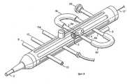
на фиг. 8 увеличенное схематическое изображение устройства привода - управления для альтернативного воплощения настоящего изобретения, в котором применяется баллон ангиопластики с вращающимся наконечником атероэктомии; это устройство привода управления на фиг. 8 способно осуществлять вращение как в направлении часовой, так и против часовой стрелки;
на фиг. 9 увеличенное пространственное изображение альтернативного воплощения настоящего изобретения, в котором применяется баллон ангиопластики с вращающимся наконечником аблятора фиксированного диаметра, и которое предназначено для использования с устройством привода управления на фиг. 8;
на фиг. 10 увеличенное пространственное изображение другого воплощения настоящего изобретения, в котором применяется баллон ангиопластики с вращающимся наконечником аблятора и изменяемым диаметром, которое также предназначено для использования с устройством привода управления на фиг. 8;
на фиг. 11 вид на увеличенный продольный разрез объединенного воплощения наконечник атероэктомии баллон ангиопластики на фиг. 10.For a detailed description of this invention, reference will be made to the accompanying drawings, where:
in FIG. 1 is a schematic representation of the present invention with its control drive device at its proximal end and a drive coil, an expandable tip and a guide drive located inside a flexible external catheter that surrounds this drive coil;
in FIG. 2 is a longitudinal sectional view of an expandable coil and an associated piston and an internal catheter with a coil retracted and an enlarged circumference of this coil;
FIG. 3 is a longitudinal sectional view of the coil of FIG. 2 in its elongated position with a smaller circumference;
in FIG. 4 is a longitudinal sectional view of an alternative embodiment of this coil with bellows associated with this coil for expansion;
in FIG. 5 is a longitudinal section through an alternative embodiment, with an inflated balloon used to expand the coil;
in FIG. 6 is a longitudinal sectional view of an alternative embodiment with a pair of concentrically and coaxially located telescopically extensible bushings mounted inside the coil and interacting to expand the coil;
in FIG. 7 is a longitudinal sectional view of an alternative embodiment of this expandable mother, where this coil consists of spirally wound ribbon-shaped metal strips;
in FIG. 8 is an enlarged schematic view of a drive-control device for an alternative embodiment of the present invention, wherein an angioplasty balloon with a rotating atheroectomy tip is used; this control drive device of FIG. 8 is capable of rotating both clockwise and counterclockwise;
in FIG. 9 is an enlarged spatial view of an alternative embodiment of the present invention, which uses a fixed-diameter angioplasty balloon with a rotating ablator tip, and which is intended for use with the control drive device of FIG. 8;
in FIG. 10 is an enlarged spatial view of another embodiment of the present invention that utilizes an angioplasty balloon with a rotating ablator tip and a variable diameter, which is also intended for use with the control drive device of FIG. 8;
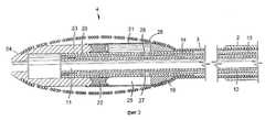
in FIG. 11 is an enlarged longitudinal sectional view of a combined embodiment of an atheroectomy tip angioplasty balloon in FIG. 10.
Эти чертежи иллюстрируют устройство настоящего изобретения, используемое для ликвидации закупорок в сосуде. Описываемые здесь воплощения являются только примерными, и могут быть модифицированы при осуществлении изобретения. These drawings illustrate the device of the present invention used to eliminate blockages in a vessel. The embodiments described herein are only exemplary, and may be modified in the practice of the invention.
Устройство привода управления 1 присоединено к одному концу гибкого катетера 2, который окружает катушку 3 вала привода. Катушка 3 вала привода предназначена для вращения с высокой скоростью внутри катетера 2, который изготовлен из биологически совместимого материала, способного выдерживать теплоту от трения, генерируемую, когда катушка 3 вала привода вращается с высокой скоростью, которая составляет от 0 до 300 000 оборотов в минуту (такая скорость может генерироваться, например, с помощью современной турбины сжатого воздуха или тому подобного). Расширяемый, регулируемого диаметра наконечник 4 катушки присоединен к катушке 3 вала привода на ее дальнем конце, а ее ближний конец присоединен к источнику вращения 5, такому как вышеупомянутая турбина сжатого воздуха, которая расположена в центре устройства 1 привода управления. Приведение в действие источника вращения 5 приводит в движение катушку 3 вала привода, которая, в свою очередь, вращает наконечник 4 регулируемого диаметра. Катушка 3 вала привода предпочтительно представляет собой конфигурацию спирально намотанного полого провода, и изготовлена из нержавеющей стали или другого подходящего материала, способного передать крутящий момент для вращения наконечника 4 катушки со скоростями, настолько высокими, как те, что были названы выше, которые предполагаются для настоящего изобретения. Такие спирально намотанные катушки, с диаметрами настолько малыми, как 0,032 дюйма, использовались в прошлом для приложений с передачами высокоскоростного вращательного момента. Гибкий катетер 2 способствует передаче сил, действующих и передаваемых катушкой 3 вала привода, и защищает сосуды тела от повреждений или травм во время вращения этого вала привода. The control drive device 1 is attached to one end of the
Проход 6 для впуска воздуха в устройство 1 привода управления принимает воздух от современного устройства управления давлением воздуха (не показано), обычно имеющегося в госпитальных установках и хорошо известных специалистам в этой отрасли техники. Воздух с контролируемым давлением прикладывается мгновенно и в течение желаемого времени вращения наконечника. Этот сжатый воздух проходит через впускной проход 6 и сообщается с впускным проходом 6а устройства привода вращения. Вращательная скорость контролируется современным тахометром, присоединенным к соединителю 7 кабеля тахометра устройства 1 привода управления. Устройство управления давлением воздуха (не показано) может регулироваться для приложения воздуха с желаемым давлением к турбине или тому подобному для осуществления желаемой скорости вращения наконечника. An air inlet passage 6 to the control drive device 1 receives air from a modern air pressure control device (not shown), typically found in hospital units and well known to those skilled in the art. Air with controlled pressure is applied instantly and during the desired time of rotation of the tip. This compressed air passes through the inlet passage 6 and communicates with the
Устройство 1 привода управления также содержит несколько проходов, которые сообщаются с различными полостями всего этого устройства атероэктомии настоящего изобретения. В общем, эти различные полости позволяют инжектировать внутрь устройства жидкости (такие как медикаменты, жидкости гидравлического возбуждения для возбуждения средства расширяемого наконечника 4 устройства, охлаждающие жидкости для понижения фрикционного нагрева во время вращения с высокой скоростью, как это далее описано ниже). Охлаждающие жидкости, например, вводят внутрь гибкого катетера 2, окружающего катушку 3 вала привода, омывают ее во время вращения. The control drive device 1 also comprises several passages that communicate with the various cavities of the entire atheroectomy device of the present invention. In general, these various cavities allow fluid to be injected into the device (such as medicaments, hydraulic excitation fluids to excite the
Если на практике необходимо визуализировать стенотическую закупорку, подлежащую обработке устройством настоящего изобретения, то это осуществляется путем инжекции контрастной среды и флуороскопической визуализацией, как это общепринято в среде специалистов в данной отрасли техники. Проход 8 устройства 1 привода управления сообщается с кольцевым пространством 9 и, кроме того, что служит как средство для инжекции контрастной среды, может быть использовано для инжектирования охлаждающей жидкости во время вращения с высокой скоростью. Проход 10 устройства 1 привода вращения сообщается с центральной полостью 11, показанной на фиг. 2, и может быть использован для инжекции через нее контрастной среды, медикаментов и других жидкостей. If in practice it is necessary to visualize the stenotic blockage to be processed by the device of the present invention, this is done by injecting a contrast medium and fluoroscopic visualization, as is customary among specialists in this field of technology. The
Обратившись к фиг. 2 можно видеть, что центральная полость 11 создана трубкой 12 гибкого катетера, которая расположена коаксильно внутри трубки 13 гибкого катетера с большим внутренним диаметром. Эти концентрически и коаксильно расположенные внутренние катетеры расположены в канале, созданном катушкой 3 вала привода, и проходят за ближний конец этой катушки внутрь устройства 1 привода управления. Это концентрическое и коаксиальное расположение гибких катетеров 12 и 13 и разность в размерах между внешним диаметром катетера 12 и внутренним диаметром катетера 13 создает кольцевую пространственную полость 14, которая сообщается с проходом 15 устройства привода управления, тем самым обеспечивая проход для целей активирования средства расширения, используемого для регулировки диаметра наконечника 4 катушки аблятора, как это описано ниже. Turning to FIG. 2 it can be seen that the
Дальние терминальные концы концентрически и коаксиально расположенных гибких катетеров 12 и 13 загерметизированы керамическим материалом 16 для обеспечения герметизации на дальнем конце кольцевой пространственной полости 14. The distal terminal ends of the concentrically and coaxially located
Центральная полость распространяется от терминального дальнего конца наконечника 4 до устройства 1 привода управления на его предельно близком конце и может быть использована для проведения наконечника 4 устройства атероэктомии настоящего изобретения к месту закупорки выбранного сосуда за счет введения направляющего провода 17, показанного на фиг. 1. The central cavity extends from the terminal distal end of the
Устройство атероэктомии настоящего изобретения внедряется в тело больного через плечевую или бедренную артерию, с использованием метода Грунцига, который хорошо известен всем кто практикует в области катетеризации. Устройство в соответствии с настоящим изобретением минимизирует повреждения, причиняемые сосуду, выбранному для введения катетера. Обычно используется оболочка устройства внедрения для доступа к сосуду в точке внедрения. Через эту, предварительно расположенную оболочку, вводят направляющий катетер и направляющий провод для направления устройства атероэктомии настоящего изобретения к выбранному стенозу, подлежащему обработке. Размер, или диаметр оболочки устройства внедрения и направляющего катетера определяется размером или диаметром устройства, которое следует ввести для обработки этой закупорки. The atheroectomy device of the present invention is introduced into the patient’s body through the brachial or femoral artery using the Grunzig method, which is well known to all who practice catheterization. The device in accordance with the present invention minimizes damage to the vessel selected for insertion of the catheter. Typically, the shell of the insertion device is used to access the vessel at the insertion point. Through this pre-positioned sheath, a guide catheter and guide wire are inserted to guide the atheroectomy device of the present invention to the selected stenosis to be treated. The size or diameter of the sheath of the insertion device and the guide catheter is determined by the size or diameter of the device that must be inserted to handle this blockage.
Настоящее изобретение, благодаря его наконечнику 4 с изменяемым регулируемым диаметром, может быть введено с помощью метода, только что описанного, но может применять оболочку устройства внедрения и направляющий катетер с диаметром, который меньше, чем его максимальный расширенный диаметр. The present invention, thanks to its
Обратимся к фиг. 2 и к фиг. 3, с помощью которых проиллюстрирована особенность изменяемого диаметра истирающего наконечника 4 этого изобретения. На фиг. 2 показано предпочтительное воплощение динамически изменяющегося истирающего наконечника катушки. Фиг.2 иллюстрирует истирающий наконечник катушки в состоянии его максимального диаметра и средство активиции (или поршень) 18 в его деактивированном состоянии. Этот поршень 18 состоит из ближней полумуфты 19, цилиндрической внутренней втулки 20 поршня, цилиндрической внешней втулки 21 поршня, скользящего кольца 22 уплотнения поршня, и дальней скользящей полумуфты 23 поршня, также содержит коническую истирающую поверхность 24 устройства настоящего изобретения. Turning to FIG. 2 and to FIG. 3, by which a feature of the variable diameter of the
Эти втулки 20 и 21 поршня, ближняя полумуфта 19 и дальняя полумуфта 23 предпочтительно изготовлены из нержавеющей стали, но могут быть изготовлены из других материалов, подходящих для желаемой функции поршня и присоединения, описанного ниже. These piston bushings 20 and 21, the
Цилиндрическая внутренняя втулка 20 поршня присоединяется к ряду витков катушки 3 вала привода в области "а", а также к ближней полумуфте 19 в области "в" сваркой по кругу, или т.п. Внешняя втулка 21 поршня приваривается по окружности или т.п. к ближней полумуфте 19. Внутренняя втулка 20 поршня концентрически и коксиально расположена над трубкой 14 гибкого катетера и закреплена герметично, что обеспечивается плотной посадкой этих элементов и связыванием их эпоксидной смолой. The cylindrical
Дальняя полумуфта 23 поршня свободна для скользящего и вращательного движения между внутренней втулкой 20 и внешней втулкой 21 поршня. Эти скользящие контактирующие поверхности могут наноситься путем осаждения тонкого тефлонового покрытия или т.п. для улучшения условий движения дальней полумуфты 23 во время осуществления функции поршня. The distal
В месте ближнего завершения дальней полумуфты 23 находится расположенное по окружности вокруг внутренней втулки 20 поршня скользящее кольцо 22 уплотнения поршня. Предпочтительно изготовленное из тефлона или из другого подходящего материала, оно является главным кольцом уплотнения и свободно для скользящего продольного осевого движения между втулками 20 и 21 поршня, создавая таким образом скользящее уплотнение между ними. At the point of near completion of the
Замкнутая полость 25 поршня является кольцевой, ограниченной терминальной дальней поверхностью полумуфты 19 и ближней терминальной поверхностью кольца 22 уплотнения поршня, внутренней терминальной поверхностью втулки 21 и внешней поверхностью стенки втулки 20 и сообщается при помощи отверстий 26 и 27 через стенку внутренней втулки 20 поршня и стенку гибкой трубки катетера 14 с полостью 15. The
Регулируемого диаметра, имеющая форму овалоида катушка 28 наконечника 4 расположена вокруг поршня. Дальние витки катушек 28 овалоида прикреплены к дальней полумуфте поршня методом сварки по окружности или подходящим способом. Это дальнее прикрепление формирует гладкое продолжение поверхности наконечника 4 внешнего овалоида и внешней поверхности дальней полумуфты 23 поршня. An adjustable diameter, ovaloid-shaped
При этом жестко намотанная катушка 28 за счет ее прикрепления к дальней полумуфте 13 и к ближней полумуфте 19 формирует возвратную пружину поршня. In this case, the hard-
Полость 14 кольцевого пространства сообщается с проходом 15 устройства привода управления 1 и проходами 26 и 27. Приложение гидравлического давления или давления другой подходящей текучей среды к проходу 15 устройства 1 привода управления будет передавать необходимую силу, заставляющую уплотнение 22 поршня двигаться в направлении дальнего конца, и толкать скользящую дальнюю полумуфту 23 поршня по направлению вперед. Когда давление в проходе 15 возрастает, главный диаметр катушки 28 овалоида в наконечнике 4 уменьшается, а овалоид удлиняется и растягивается, в пределе стремясь к правильной цилиндрической конфигурации. По мере возрастания давления активации поршня, катушка 28 овалоида также предпочтительно разматывается под действием силы тяги, развиваемой движением вперед дальней полумуфты 23. Этот поршень может иметь, например, спиральную камеру, по которой движется выступающий наружу штырь или т.п. расположенный на втулке 20, определяя предпочтительное движение наматывания или разматывания витков катушки, когда поршень деактивируется или активируется. The
Фиг.3 иллюстрирует эффект активации поршня при его максимальном переходе или движении. Катушка 28 овалоида, выполненная, например, четырехниточной, растянута под действием поршня. Figure 3 illustrates the effect of the activation of the piston at its maximum transition or movement. The
Диаметр наконечника 4 изменен от его максимального диаметра овалоида, показанного на фиг. 2, до минимального. Динамический диаметр наконечника 4 овалоида является функцией давления активации поршня, приложенного к полости 25 поршня, и силы возвратной пружины катушки 28 овалоида. Таким образом, возможно выбрать любой желаемый диаметр наконечника в пределах диапазона значений, ограниченных максимальным и минимальным диаметрами, выбирая соответствующее давление активации поршня, приложенное к проходу 15 устройства 1 привода управления. Это давление активации может устанавливаться и контролироваться с использованием стандартных манометров и систем давления, повсеместно используемых и хорошо известных специалистам в этой отрасли техники. The diameter of the
Вернемся снова к фиг.1, где показана кнопка 29 управления воздушным зажимом, который установлен в устройстве 1 привода управления. Этот воздушный зажим удерживает направляющий провод 17 в рабочем положении все время, за исключением момента, когда нажата кнопка клапана. Таким образом, этот направляющий провод 17 нормально удерживается во время вращения устройства, и отпускается для продвижения на полную длину этого устройства атероэктомии. Let us return again to Fig. 1, where the air
На поверхность истирающего наконечника 4 нанесены частицы (такие как алмазная пыль), которые могут частично или полностью покрывать его внешнюю поверхность от самой дальней внешней поверхности 24 дальней полумуфты 23 поршня до ближнего окончания 30 наконечника 4 овалоида. Particles (such as diamond dust) are deposited on the surface of the
Размер частиц истирающего материала должен быть одинаковым по всей истирающей поверхности наконечника. Диаметр частиц должен находиться в диапазоне значений от примерно 10 до примерно 100 микрон, с предпочтительным диапазоном значений от 10 до 20 микрон. С истирающими частицами такого размера, вращающимися со скоростями, предполагаемыми для настоящего изобретения, размер частиц отбрасываемого стенотического материала будет составлять от 5 до 8 микрон в диаметре, что меньше, чем типовой диаметр красных кровяных телец. При таком малом размере частиц, отбрасываемые кусочки стенотического материала могут быть удалены телом естественно, через капилляры, и нет необходимости в дополнительных средствах для сбора отходов. The particle size of the abrasive material should be the same across the abrasive surface of the tip. The particle diameter should be in the range of from about 10 to about 100 microns, with a preferred range of from 10 to 20 microns. With abrasive particles of this size, rotating at the speeds envisioned for the present invention, the particle size of the discarded stenotic material will be 5 to 8 microns in diameter, which is smaller than the typical diameter of red blood cells. With such a small particle size, discarded pieces of stenotic material can be removed by the body naturally, through capillaries, and there is no need for additional means for collecting waste.
Истирающую способность наконечнику 4 можно также придать другими способами, например, наклепом, когда поверхности наконечника сообщается шероховатая текстура, создаваемая множеством ямок и зарубок с относительно острыми краями. Наконечник 4 устройства настоящего изобретения, обладает способностью к истиранию при движении наконечника через стеноз как в прямом, так и в обратном направлении. The abrasion ability of the
Обратимся теперь к фиг. 4. Здесь показан продольный разрез альтернативного воплощения наконечника 4 устройства атероэктомии настоящего изобретения, в котором сильфон 31 заменил поршень как средство расширения катушки овалоида. Сильфон 32 изготовлен из никеля или другого подходящего тонкостенного материала и присоединен на своем ближнем конце с дальней поверхностью ближней полумуфты 19, которая, в свою очередь, присоединена к множеству витков катушки 28 наконечника 4 сваркой по окружности или т.п. Трубка катетера 13 герметично присоединена к ближнему концу полумуфты 19 и содержит пару концентрически и коаксиально расположенных гибких трубок, формирующих полость 32 кольцевого пространства между собой. Трубка катетера 13 концентрически и коаксиально расположено внутри катушки 3 вала привода. Полость 32 сообщается через проходы 33 в полумуфте 19 с внутренней полостью сильфона 31 на его ближнем конце, его дальний конец присоединен к скользящей дальней полумуфте 23 наконечника. Катушка 28 на ее дальнем конце присоединена к внешней поверхности полумуфты 23 наконечника сваркой по окружности или т.п. Металлическая направляющая трубка 34 присоединена к дальнему концу трубки 13 катетера и выступает оттуда через сильфон в центральный осевой канал полумуфты 23 наконечника, который свободен для вращательного и продольного скользящего движения в направлении оси по направляющей трубке 34. При приложении давления активации продольное расширение сильфона 31 заставляет катушку 28 наконечника растягиваться, уменьшая ее окружность или диаметр способом, подобным тому, что был описан в связи с воплощением, показанным на фиг. 2 и на фиг. 3. Снятие давления возбуждения заставит этот сильфон сжиматься за счет силы упругости. Когда этот сильфон находится в своем сжатом состоянии, диаметр наконечника 4 овалоида является максимальным, а когда сильфон находится в своем расширенном состоянии, диаметр наконечника минимален. Фиг. 4 иллюстрирует этот сильфон в его расширенном состоянии. Увеличенный диаметр этой катушки, когда сильфон находится в сжатом состоянии, указан в центральной части чертежа точечными линиями. Turning now to FIG. 4. This is a longitudinal sectional view of an alternative embodiment of the
Обратимся к фиг. 5, на которой показано поперечное сечение альтернативного воплощения наконечника 4, в котором баллон 35 высокого давления, такой как те, что широко используются в устройствах ангиопластики, использован как средство расширения катушки наконечника. В этом воплощении наконечник 4 нормально находится в состоянии его минимального диаметра. Как в ранее описанных воплощениях, полость 14 кольцевого пространства передает давление, необходимое для расширения баллона 35. Когда баллон 35 расширяется, он расширяет центральную часть катушки 28 наконечника. Это приводит к увеличению диаметра наконечника, что одновременно изменяет форму овалоида наконечника 4, увеличивая, например, его центральную часть 36. Turning to FIG. 5, which shows a cross-section of an alternative embodiment of
В случае выполнения устройства, согласно фиг. 5, на трубке 13 гибкого катетера закреплен баллон 35, сообщающийся через отверстия 37, 38 с полостью 14 между трубкой 13 и трубкой 12, герметизированной на дальнем конце металлической трубкой скольжения 39. Указанная металлическая трубка установлена с возможностью телескопического перемещения в дальней полумуфте 23. При этом ближняя полумуфта 19 установлена с возможностью поворота на металлической трубке 40, которая снабжена штырем 41, прикрепленным к ней с помощью сварки или т.п. В ближней полумуфте 19 для взаимодействия со штырем 41 выполнена прорезь в виде сектора, угол которого составляет 350o для ограничения перемещения полумуфты 19 по металлической трубке 40. К последней жестко прикреплена катушка 3 вала привода, благодаря чему она может приводить в движение ближнюю муфту 19. Катушка 28, аналогично предыдущим вариантам исполнения, прикреплена к ближней и дальней полумуфтам. При введении в баллон 35 текучей среды, а также при осевом перемещении и вращении наконечника 24 относительно металлической трубки 39 и повороте ближней полумуфты 19 на 350o относительно трубки 40, катушка 28 наконечника может разматываться или наматываться. Баллон 3 при его максимальной накачке заставляет центр овалоида принять значение его максимального диаметра. Устранение давления из баллона заставляет его сжиматься, позволяя катушке вернуться в ее нормальное состояние пониженного диаметра.In the case of the device according to FIG. 5, a
Кроме того, варианты устройства, изображенные на фиг. 2-4, а обсуждавшиеся выше, также как и варианты, представленные на фиг.6, 7, 10 и 11, могут быть снабжены внутренним баллоном, подобным баллону 35 на фиг. 5. Этот баллон может накачиваться для зацепления с катушкой, но не для расширения ее, а для использования в качестве как средства для придания жесткости или твердости наконечнику катушки во время вращения в высокой скоростью с целью удаления стенотического материала. Когда баллон 35 спущен, это позволяет наконечнику оставаться гибким для маневрирования внутри кривых и плотных мест внутри сосуда. Такой баллон также может служить для заполнения пустых мест между витками катушки, не позволяя материалу закупорки заполнять внутреннюю часть этой катушки. In addition, the embodiments of the device shown in FIG. 2-4, and discussed above, as well as the options presented in FIGS. 6, 7, 10 and 11, may be provided with an inner cylinder similar to
Фиг. 6 иллюстрирует поперечный разрез альтернативного воплощения, в котором вторая катушка 43 коаксиально расположена внутри катушки 3 вала. Эта внутренняя катушка 43 свободна для скольжения внутри катушки 3 вала привода и растянута на всю длину устройства. Пара таких катушек, изготавливаемых компанией "Лейк риджен маньюфэкчуринг компани инк оф Часка" шт. Миннесота, может оказаться подходящей для использования в этом воплощении, но и другие или эквивалентные катушки могут естественно быть использованы. Дальний конец этой внутренней катушки 43 присоединен к дальней полумуфте 23 наконечника через внутреннюю втулку скольжения 44. Наконечник 4 овалоида катушки 28 присоединен к дальней и ближней полумуфтам, как описано ранее. Внешняя втулка 45 скольжения телескопически раздвигается над внутренней втулкой 44 скольжения и расположена своим ближним концом в центральном осевом канале ближней полумуфты 19. Эта внутренняя втулка 44 скольжения предпочтительно способна к продольному осевому движению и к вращению внутри внешней втулки 45 скольжения. FIG. 6 illustrates a cross-sectional view of an alternative embodiment in which the
Наконечник 4 фиг. 6 нормально находится в состоянии своего максимального диаметра и принуждается к уменьшению этого диаметра за счет продольного движения внутренней катушки 43 внутри катушки 3 вала привода в направлении ее дальнего конца. При этом, дальняя полумуфта 23 наконечника движется вперед и принуждает катушку 28 наконечника растягиваться. Таким образом диаметр наконечника может быть уменьшен. Диаметр наконечника 4 в этом воплощении есть функция продольного смещения дальней полумуфты 23 относительно ближней полумуфты 19. Катушка 28 наконечника для этого воплощения может быть продолжением катушки 3 вала привода, как показано на фиг. 2, или индивидуальным сегментом катушки, как показано на фиг. 5. И наоборот, эти внутренняя и внешняя полумуфты скольжения могут удерживаться от относительного продольного движения, а могут просто вращаться относительно друг друга. Это наматывание или разматывание катушки будет вызывать снижение или увеличение соответственно диаметра катушки, даже при отсутствии продольного перемещения этих внутренней и внешней полумуфт.
Катушка 28 наконечника 4 овалоида может быть заменена на овалоид из отложенного металла, такого, как никель с толщиной стенок меньше, чем 0,002 дюйма. Далее, этому наконечнику из предварительно отложенного металла может быть придана характеристика катушки за счет того, что ленты в центре или на вершине овалоида шире и уменьшаются по ширине по мере опускания склонов овалоида к дальнему и ближнему меньшим диаметрам. Здесь может быть одна пространственная спираль или множество смежных спиралей, составляющих катушку. Эта альтернатива катушки из отложенного металла представляет то, что может быть названо "лимонной коркой". Иллюстрация такого воплощения показана для примера на фиг. 7. The
Теперь обратимся к чертежам на фиг. 8-11, где показаны альтернативные воплощения этого изобретения, содержащие объединенные устройства атероэктомии и баллонной ангиопластики и один тип устройства привода управления, которое может применяться с такими альтернативными воплощениями. Фиг. 8 иллюстрирует тип системы 10, предназначенной для использования с предпочтительными воплощениями изобретения, показанными на фиг. 9-11. Устройство 1 привода управления на фиг. 8 аналогично устройству привода управления на фиг. 1, со следующими главными различиями. Впускная трубка 6 подачи воздуха включает в себя жесткие трубки 6a и 6b и гибкие пластиковые трубки 6c и 6d. Вращающаяся турбина 1 привода будет принимать ввод воздуха от одной из трубок 6a или от одной из трубок 6b. Переключатель 46 клапана турбины, расположенный на устройстве привода управления фиг. 8, сообщается с турбиной 5 привода как средство для выбора направления вращения наконечника в прямом направлении (т. е. против часовой стрелки, обозначенная буквой "F") или в обратном направлении (т.е. по часовой стрелке, обозначенном буквой "P"). Turning now to the drawings in FIG. 8-11, alternative embodiments of this invention are shown comprising combined atheectomy and balloon angioplasty devices and one type of control actuator device that can be used with such alternative embodiments. FIG. 8 illustrates a type of
Как указывалось ранее, воздух подводится к впускной трубке 7 с регулируемым давлением и сообщается с турбиной 1, которая расположена внутри устройства привода управления. Если воздух направляется по трубке 6a, гибкой пластиковой к одной стороне лопастей турбины, они будут вращаться в одном направлении, т.е. по направлению вперед, а если воздух направляется по трубке 6b к противоположным сторонам лопастей турбины, они будут вращаться в противоположном направлении, т. е. по направлению назад. Эта способность наконечника вращаться как в направлении по часовой стрелке, так и против обеспечивает врачу повышенную гибкость при выполнении процедур. Баллон ангиопластики 47 (фиг.9-11) накачивается через трубку 15а устройства 1 привода управления на фиг.8. Накачиваемый баллон 47 приводится в действие приложением гидравлического давления, используя в качестве среды давления солевой раствор или другую приемлемую жидкость. Общепринятые манометры регулирования давления баллона, такие как шприцы-манометры, могут быть соединены с впускной трубкой 15а баллона для осуществления контроля за давлением в баллоне. Источник давления сообщается с баллоном через кольцевую полость 14, показанную на фиг.11, которая сообщается с впускной трубкой 15а. Возвращаясь к фиг. 9, следует указать, что здесь показано воплощение объединенного устройства атероэктомии и баллонной ангиопластики, в котором применяется вращающийся наконечник 4а аблятора фиксированного размера. Этот овальный наконечник 4а является пустотелым и имеет толщину стенок в диапазоне от 0,001 дюйма или т. п. Этот овальный наконечник 4а может быть изготовлен, например, методами отложения или гидроформирования металла, или другими методами формирования тонкостенных элементов. Этот наконечник 4а имеет истирающую или "покрытую песком" поверхность, которая может содержать покрытие из бриллиантовой пыли 48, или может содержать истирающую поверхность, полученную наклепом или другими способами нанесения металла,
Полый наконечник 4а содержит тонкостенный трубчатый металлический элемент (не показан), расположенный в нем центрально и аксиально. Дальние концы наконечника 4а и его центрально расположенной трубки на дальнем конце соединены, например, методом сварки. Ближние концы этого трубчатого центрального элемента и овального наконечника 4а соединены, также, например сваркой, при этом катушка 3 вала привода соединена, снова с помощью сварки, с частью этого тонкостенного трубчатого металлического элемента, которая выступает на ближнем конце наконечника.As indicated previously, air is supplied to the inlet pipe 7 with a controlled pressure and communicates with the turbine 1, which is located inside the control drive device. If air is guided through a
The
Баллон 47 ангиопластики присоединен к катушке 3 вала привода. Дальний конец баллона 47 расположен вблизи от овального наконечника 4а и закреплен с помощью гибкого клея (такого как эпоксидная смола на базе полиуретана или т. п. ), а дальний, удерживающий кольцевой маркер 49, расположен по окружности вокруг места дальнего присоединения баллона к катушке вала привода. Ближний конец баллона аналогично присоединен к катушке 3 вала привода в точке, близкой к трубке 2 гибкого катетера, и содержит ближний удерживающий кольцевой маркер 50. The
Эти удерживающие баллон кольца 49, 50 предпочтительно изготавливаются из такого материала, как платино-иридиевый сплав или т.п. Кроме осуществления фиксации баллона, кольца 49, 50 служат как маркеры, облегчающие флуроскопическую визуализацию, и способствуют размещению баллона в желаемом месте. These balloon retaining rings 49, 50 are preferably made from a material such as platinum-iridium alloy or the like. In addition to fixing the balloon, rings 49, 50 serve as markers to facilitate fluoroscopic imaging, and facilitate the placement of the balloon in the desired location.
Баллон 47 может быть изготовлен из нейлона или другого материала, обычно используемого в катетерах баллонной ангиопластики. Предпочтительно, чтобы осевая длина этого баллона соответствовала диапазону длин общепринятых баллонов ангиопластики, но этот баллон может изготавливаться с дополнительными или различными или с изменяющимися длинами, которые более адекватно реагируют на объединенное приложение атероэктомии и ангиопластики в одной процедуре, в том, что относится к коронарным или периферийным процедурам. Диаметры этих накачиваемых баллонов будут обеспечиваться в диапазоне размеров для заданного размера наконечника 4а, для удовлетворения требований к специфической процедуре, как это принято в известных процедурах ангиопластики. The
Расстояние между ближним концом баллона 47 у кольца 50 и дальним концом трубки 2 катетера предпочтительно должно быть таково, что когда катушка 3 вала привода полностью втянута в трубку 2 катетера (например, отводе назад кнопки 51 устройства привода управления, это удерживающее кольцо 50 не должно входить в полость трубки катетера 2, т.е. если бы баллон 47 втягивался в трубку 2 катетера, вращательный привод к устройству был бы заблокирован, а также была бы зашунтирована подача воздуха от вращательного устройства привода из-за того, что кольцо 50, близко примыкающее к дальнему концу катетера 2, не допускает вращения баллона в трубке 2. Возможно повреждение баллона. The distance between the proximal end of the
Обратимся теперь к фиг.10 и к фиг.11, где показано воплощение объединенного устройства атероэктомии баллонной ангиопластики этого изобретения, в котором применяется вращающийся наконечник 4 аблятора изменяемого диаметра, который может быть сформирован из катушки, имеющей один непрерывный пучок, намотанный на пространственную спираль, или принимать форму множества пучков, намотанных на переплетающиеся пространственные спирали (например, такую, как четырехниточная катушка, показанная на фиг.3) или он может принимать форму катушки из отложенного металла (такой, как показана на фиг.7), или другую подходящую форму катушки, как обсуждалось выше. В целях иллюстрации, а не в порядке ограничения, наконечник 4 для этого воплощения показан и описан как наконечник из отложенного металла, подобно наконечнику 4а за исключением того, что эта версия полого овального наконечника выполнена в виде ленточной пружины. Шлицы 52 могут быть прорезаны в тонкой стенке овального наконечника 4 лазером, электронным лучом, химической эрозией, электротравлением или другим подходящим методом. Этот истирающий наконечник 4 сформирован в овальную пружину благодаря упомянутым шлицам 52, которые могут представлять собой один спиральный шлиц, или множество переплетающихся шлицов. Этот пружинный овальный наконечник 4 предпочтительно способен растягиваться и вращаться относительно своей центральной оси. Будучи растянут и вращаясь, этот пружинный овальный наконечник 4 удлиняется и его максимальный диаметр будет уменьшен на величину, пропорциональную значению удлинения и/или поворота. Как указывалось выше, удлинение может быть получено без вращения, или вращение без удлинения (например, для снижения величины диаметра наконечника 4). Таким образом можно варьировать диаметр и длину этого наконечника. Наконечник 4 имеет истирающую поверхность, подобную, например, поверхности наконечника 4а. Turning now to FIG. 10 and FIG. 11, there is shown an embodiment of a combined balloon angioplasty atheectomy device of this invention, in which a
Баллон ангиопластики 47 расположен на фиг.10 и на фиг.11 на катушке 3 вала привода, между наконечником 4 овальной пружины и дальним концом катетера 2. Баллон 47 имеет длину и максимальный диаметр, сравнимые с длиной и максимальным диаметром, указанным выше, для баллона на фиг.9. The
Центрально расположенные внутри истирающего наконечника 4 пружинного овалоида, находятся трубчатые металлические втулки 53 и 54. Втулка 53 присоединена, например, с помощью сварки к дальнему концу тонкостенного наконечника 4 овалоида. Втулка 54 телескопически раздвигается над втулкой 53. Centrally located inside the
Катушка 3 вала привода присоединена, например, с помощью сварки к ближнему концу втулки 54. Ближний конец истирающего наконечника 4 овалоида присоединен с помощью сварки к катушке 3 вала привода и втулке 54. The
Свернутая из многониточного провода, катушка 43 расположена центрально внутри втулки 54 и, соответственно, гибкой пластической трубки катетера 12. Катушка 43 тянется по всей длине катетера и устройства 1 привода управления. Втулка 53 присоединена, например, с помощью сварки, к дальнему концу катушки привода 43. Наконечник 4 фиг.11 нормально находится в состоянии своего максимального диаметра и принуждается к уменьшению своего диаметра движением внутренней катушки 43 относительно катушки 3 вала привода, и/или относительным вращением этих двух катушек. Когда внутренняя катушка 43 толкается и/или вращается относительно катушки 3 вала привода, наконечник 4 принуждается к удлинению в осевом направлении. Диаметр наконечника уменьшается. Таким образом диаметр наконечника 4 в этом воплощении есть функция продольного смещения между дальним концом наконечника в точке "а", и ближним концом этого наконечника в точке "b"; а также функцией величины относительного поворота между двумя катушками 43 и 3. Опять, как указывалось выше, расширение может осуществляться без вращения или вращение без расширения, например, для того, чтобы уменьшить диаметр этого наконечника. Удерживающее кольцо 49 баллона расположено вблизи от области "b". Расстояние между областью "b" и дальним концом кольца 49 таково, что катушке 3 вала привода разрешено пригибаться вдоль ее длины между баллоном и овальным наконечником 4. Rolled from a multi-strand wire, the
Внутри катушки 3 вала привода коаксиально расположены трубки 12, 13 гибкого катетера, которые формируют кольцевую полость 14, которая служит для накачивания баллона 47. Множество боковых проходов или отверстий 55, 56 и 57 в стенке трубки 13 катетера, находящихся внутри баллона 47, и между герметизированными точками прикрепления концов баллона к катушке вала привода, служат для сообщения сжатой текучей среды с внутренней областью баллона 47. На ближних концах баллона 47 и трубок 12, 13 катетера эпоксидный герметизирующий материал служит для герметизации ближнего конца кольцевой полости 14. Этот герметизирующий материал служит для присоединения катушки вала привода к коаксиально расположенным трубкам катетера, баллону и ближнему удерживающему кольцу 49. Аналогично, эпоксидный герметизирующий материал служит для герметизации ближнего конца баллона 47 у кольца 50 и для присоединения его к катушке вала привода и внешней поверхности трубки 13 катетера. A
Итак, нетрудно видеть, что с любым из воплощений на фиг.9, на фиг.10 и на фиг. 11, в течение любого одного прохода в окклюдированный сосуд врач может выполнить одну процедуру атероэктомии с фиксированным диаметром наконечника 4а или с изменяемым диаметром наконечника 4, или комбинацию процедуры атероэктомии с процедурой баллонной ангиопластики, т.е. процедуру атероэктомии с фиксированным диаметром наконечника 4а, объединенную с процедурой баллонной ангиопластики, использующей4 баллон 47, или процедуру атероэктомии с изменяемым диаметром, использующую наконечник 4,объединенную с процедурой баллонной ангиопластики, использующей баллон 47, с целью получения наилучшего результата для пациента. Однако, следует заметить, как это хорошо известно специалистам в этой отрасли техники, процедуру атероэктомии и процедуру баллонной ангиопластики не следует выполнять одновременно. So, it is easy to see that with any of the embodiments of FIG. 9, FIG. 10 and FIG. 11, during any one passage into the occluded vessel, the doctor may perform one atheectomy procedure with a fixed
Одним конкретным преимуществом воплощений настоящего изобретения, которые используют регулируемый диаметр наконечника катушки, является то, что этот наконечник катушки может претерпеть динамическое изменение по форме или очертаниям и истирает стеноз во время лечения. Например, в том случае, когда стеноз расположен в месте изгиба или искривления сосуда, или как-то иначе нерегулярен по своей форме, наконечники катушки с регулируемым диаметром настоящего изобретения достаточно гибки, чтобы следовать искривленной или нерегулярной форме этого стеноза; искривленный или деформированный наконечник затем может вращаться с целью устранения этого стеноза. При этом, если имеется необычно твердый стеноз, расположенный в сосуде, наконечники катушки настоящего изобретения, вращаясь на высокой скорости, чтобы обработать этот стеноз, могут деформировать свою обычную форму овалоида в результате ударов об этот твердый стеноз. Деформируясь таким образом, наконечник катушки будет делать более мелкий начальный проход, т.е. первоначально он будет истирать меньше вещества этого стеноза. Затем, по мере того как обработка продолжается и больше вещества стеноза удаляется, этот вращающийся наконечник катушки будет стремиться восстановить свою форму овалоида и истирающее действие вернется к нормальному значению. В этих обоих случаях регулируемый наконечник катушки будет проходить через такие стенозы, постепенно истирая их, а не пытаясь прорваться через них в начале столкновения. Вышеупомянутое динамическое изменение формы таким образом позволяет наконечникам катушек с регулируемым диаметром, согласно настоящему изобретению, избегать избыточных рассечений или прорывов при столкновении с искривленными или имеющими нерегулярную форму стенозами, или с очень твердыми стенозами, как указано выше. One particular advantage of embodiments of the present invention that use an adjustable diameter of the coil tip is that this coil tip can undergo a dynamic change in shape or shape and abrade stenosis during treatment. For example, when the stenosis is located at the point of bending or curving of the vessel, or is otherwise irregular in shape, the tips of the coil with an adjustable diameter of the present invention are flexible enough to follow the curved or irregular shape of this stenosis; a curved or deformed tip can then rotate to eliminate this stenosis. Moreover, if there is an unusually hard stenosis located in the vessel, the tips of the coils of the present invention, rotating at high speed to treat this stenosis, can deform their normal ovaloid shape as a result of impacts on this solid stenosis. Deforming in this way, the tip of the coil will make a smaller initial pass, i.e. initially it will abrade less of the substance of this stenosis. Then, as the treatment continues and more stenosis material is removed, this rotating tip of the coil will tend to restore its ovaloid shape and the abrasive effect will return to normal. In both of these cases, the adjustable tip of the coil will pass through such stenoses, gradually abrading them, rather than trying to break through them at the beginning of the collision. The aforementioned dynamic change in shape in this way allows the tips of the adjustable diameter coils of the present invention to avoid excessive cuts or breakouts when faced with bent or irregularly shaped stenoses, or with very hard stenoses, as described above.
Хотя здесь были описаны предпочтительные воплощения этого изобретения, в устройстве могут быть сделаны различные модификации, не отходящие от принципов этого изобретения. Although preferred embodiments of this invention have been described herein, various modifications may be made to the device without departing from the principles of this invention.
Claims (48)
Translated fromRussianApplications Claiming Priority (9)
| Application Number | Priority Date | Filing Date | Title |
|---|---|---|---|
| US07/731,109US5217474A (en) | 1991-07-15 | 1991-07-15 | Expandable tip atherectomy method and apparatus |
| US731.109 | 1991-07-15 | ||
| WO91/06381 | 1991-09-05 | ||
| WOPCT/US91/06381 | 1991-09-05 | ||
| PCT/US1991/006381WO1993001849A1 (en) | 1991-07-15 | 1991-09-05 | Expandable tip atherectomy method and apparatus |
| US07/805,577US5308354A (en) | 1991-07-15 | 1991-12-10 | Atherectomy and angioplasty method and apparatus |
| US805577 | 1991-12-10 | ||
| US805,577 | 1991-12-10 | ||
| PCT/US1992/005993WO1993001753A2 (en) | 1991-07-15 | 1992-07-15 | Atherectomy and angioplasty method and apparatus |
Publications (2)
| Publication Number | Publication Date |
|---|---|
| RU94014232A RU94014232A (en) | 1995-11-27 |
| RU2093087C1true RU2093087C1 (en) | 1997-10-20 |
Family
ID=27376806
Family Applications (1)
| Application Number | Title | Priority Date | Filing Date |
|---|---|---|---|
| RU9294014232ARU2093087C1 (en) | 1991-07-15 | 1992-07-15 | Apparatus and method for treating occlusion in vessel (alternative embodiments), method for removing from vessel |
Country Status (10)
| Country | Link |
|---|---|
| EP (1) | EP0596928B1 (en) |
| JP (1) | JPH07503623A (en) |
| AT (1) | ATE191325T1 (en) |
| AU (1) | AU652475B2 (en) |
| BR (1) | BR9206279A (en) |
| CA (1) | CA2113438C (en) |
| DE (1) | DE69230883T2 (en) |
| ES (1) | ES2147730T3 (en) |
| RU (1) | RU2093087C1 (en) |
| WO (1) | WO1993001753A2 (en) |
Cited By (5)
| Publication number | Priority date | Publication date | Assignee | Title |
|---|---|---|---|---|
| RU2363411C1 (en)* | 2007-12-18 | 2009-08-10 | Государственное образовательное учреждение высшего профессионального образования "БАШКИРСКИЙ ГОСУДАРСТВЕННЫЙ МЕДИЦИНСКИЙ УНИВЕРСИТЕТ Федерального Агентства по здравоохранению и социальному развитию" (ГОУ ВПО БГМУ РОСЗДРАВА) | Method of remote injection of liquid bone cement during operation of transcutaneous puncture vertebroplasty and device to this end |
| RU2378996C2 (en)* | 2004-06-09 | 2010-01-20 | Овалум Лтд. | Drill for passing blood-vessel occlusions |
| RU2476173C1 (en)* | 2011-10-24 | 2013-02-27 | Дахир Курманбиевич Семенов | Method of removing clogging material (versions) and atheroectomy micromachine (versions) |
| RU2528966C2 (en)* | 2009-10-01 | 2014-09-20 | Кардионити | Cutting cylinder configuration and method for making it |
| RU173451U1 (en)* | 2017-01-27 | 2017-08-28 | Закрытое Акционерное Общество Научно-Производственное Предприятие "Мединж" | SYRINGE FOR PRESSURE IN A CYLINDER CATHETER |
Families Citing this family (30)
| Publication number | Priority date | Publication date | Assignee | Title |
|---|---|---|---|---|
| US5501694A (en)* | 1992-11-13 | 1996-03-26 | Scimed Life Systems, Inc. | Expandable intravascular occlusion material removal devices and methods of use |
| US5792157A (en)* | 1992-11-13 | 1998-08-11 | Scimed Life Systems, Inc. | Expandable intravascular occlusion material removal devices and methods of use |
| US5836868A (en)* | 1992-11-13 | 1998-11-17 | Scimed Life Systems, Inc. | Expandable intravascular occlusion material removal devices and methods of use |
| US5897567A (en)* | 1993-04-29 | 1999-04-27 | Scimed Life Systems, Inc. | Expandable intravascular occlusion material removal devices and methods of use |
| CA2161640C (en)* | 1993-04-29 | 2005-04-12 | Thomas V. Ressemann | Expandable intravascular occlusion material removal device |
| WO1996029014A1 (en)* | 1995-03-22 | 1996-09-26 | Evi Corporation | Intra-artery obstruction clearing apparatus and methods |
| RU2089132C1 (en)* | 1995-09-05 | 1997-09-10 | Автандил Михайлович Бабункашвили | Means for maintaining lumen of vessel or hollow organ and apparatus containing said means and intended to restore lumen of vessel or hollow organ |
| US5766192A (en)* | 1995-10-20 | 1998-06-16 | Zacca; Nadim M. | Atherectomy, angioplasty and stent method and apparatus |
| US6183487B1 (en) | 1997-03-06 | 2001-02-06 | Scimed Life Systems, Inc. | Ablation device for reducing damage to vessels and/or in-vivo stents |
| US6015420A (en)* | 1997-03-06 | 2000-01-18 | Scimed Life Systems, Inc. | Atherectomy device for reducing damage to vessels and/or in-vivo stents |
| JP3611799B2 (en)* | 2001-04-06 | 2005-01-19 | 有限会社日本エレクテル | Multipurpose ablation balloon catheter |
| CN100502806C (en) | 2001-11-09 | 2009-06-24 | 诺沃斯特公司 | Balloon catheter with non-deployable stent |
| US20040111108A1 (en) | 2001-11-09 | 2004-06-10 | Farnan Robert C. | Balloon catheter with non-deployable stent |
| US7179269B2 (en) | 2002-05-20 | 2007-02-20 | Scimed Life Systems, Inc. | Apparatus and system for removing an obstruction from a lumen |
| US8080026B2 (en) | 2003-01-21 | 2011-12-20 | Angioscore, Inc. | Apparatus and methods for treating hardened vascular lesions |
| US7686824B2 (en)* | 2003-01-21 | 2010-03-30 | Angioscore, Inc. | Apparatus and methods for treating hardened vascular lesions |
| WO2004100772A2 (en) | 2003-05-12 | 2004-11-25 | University Of Florida | Devices and methods for disruption and removal of luninal occlusions |
| US10076641B2 (en) | 2005-05-11 | 2018-09-18 | The Spectranetics Corporation | Methods and systems for delivering substances into luminal walls |
| US8597313B2 (en)* | 2007-06-11 | 2013-12-03 | Cardiovascular Systems, Inc. | Eccentric abrading head for high-speed rotational atherectomy devices |
| US8551128B2 (en)* | 2007-12-06 | 2013-10-08 | Cardiovascular Systems, Inc. | Rotational atherectomy device with pre-curved drive shaft |
| US8758377B2 (en)* | 2008-05-30 | 2014-06-24 | Cardiovascular Systems, Inc. | Eccentric abrading and cutting head for high-speed rotational atherectomy devices |
| US20100076476A1 (en)* | 2008-07-25 | 2010-03-25 | To John T | Systems and methods for cable-based tissue removal |
| EP2380604A1 (en) | 2010-04-19 | 2011-10-26 | InnoRa Gmbh | Improved coating formulations for scoring or cutting balloon catheters |
| US8632559B2 (en) | 2010-09-21 | 2014-01-21 | Angioscore, Inc. | Method and system for treating valve stenosis |
| US9492190B2 (en)* | 2011-02-09 | 2016-11-15 | Covidien Lp | Tissue dissectors |
| GB2519057A (en)* | 2013-08-02 | 2015-04-15 | Martin Sabado | Minimally invasive device and method for treating vascular disorders |
| US10117668B2 (en) | 2013-10-08 | 2018-11-06 | The Spectranetics Corporation | Balloon catheter with non-deployable stent having improved stability |
| US10478213B2 (en)* | 2015-06-25 | 2019-11-19 | Covidien Lp | Tissue-removing catheter with adjustable cross-sectional dimension |
| CN109893212B (en)* | 2019-04-17 | 2021-07-06 | 李宽正 | Soft Hydraulic Tissue Forceps |
| CN109893243B (en)* | 2019-04-17 | 2021-07-09 | 李宽正 | Minimally Invasive Soft Hydraulic Bipolar Electrocoagulation |
Family Cites Families (7)
| Publication number | Priority date | Publication date | Assignee | Title |
|---|---|---|---|---|
| FR1585065A (en)* | 1968-06-24 | 1970-01-09 | ||
| US4030503A (en)* | 1975-11-05 | 1977-06-21 | Clark Iii William T | Embolectomy catheter |
| US4706671A (en)* | 1985-05-02 | 1987-11-17 | Weinrib Harry P | Catheter with coiled tip |
| US4650466A (en)* | 1985-11-01 | 1987-03-17 | Angiobrade Partners | Angioplasty device |
| AU2829189A (en)* | 1987-12-14 | 1989-07-19 | Devices For Vascular Intervention, Inc. | Atherectomy device with angioplasty balloon and method |
| US5100425A (en)* | 1989-09-14 | 1992-03-31 | Medintec R&D Limited Partnership | Expandable transluminal atherectomy catheter system and method for the treatment of arterial stenoses |
| US5030201A (en)* | 1989-11-24 | 1991-07-09 | Aubrey Palestrant | Expandable atherectomy catheter device |
- 1992
- 1992-07-15ATAT92915850Tpatent/ATE191325T1/ennot_activeIP Right Cessation
- 1992-07-15CACA002113438Apatent/CA2113438C/ennot_activeExpired - Fee Related
- 1992-07-15BRBR9206279Apatent/BR9206279A/ennot_activeIP Right Cessation
- 1992-07-15ESES92915850Tpatent/ES2147730T3/ennot_activeExpired - Lifetime
- 1992-07-15RURU9294014232Apatent/RU2093087C1/ennot_activeIP Right Cessation
- 1992-07-15JPJP5502980Apatent/JPH07503623A/enactivePending
- 1992-07-15WOPCT/US1992/005993patent/WO1993001753A2/enactiveIP Right Grant
- 1992-07-15EPEP92915850Apatent/EP0596928B1/ennot_activeExpired - Lifetime
- 1992-07-15AUAU23398/92Apatent/AU652475B2/ennot_activeCeased
- 1992-07-15DEDE69230883Tpatent/DE69230883T2/ennot_activeExpired - Fee Related
Non-Patent Citations (1)
| Title |
|---|
| 1. US, патент, 4706671, кл. A 61 M 25/00, 1937. 2. US, патент, 4990134, кл. A 61 B 17/20, 1987. 3. US, патент, 4445509, кл. A 61 B 17/32, 1984.* |
Cited By (6)
| Publication number | Priority date | Publication date | Assignee | Title |
|---|---|---|---|---|
| RU2378996C2 (en)* | 2004-06-09 | 2010-01-20 | Овалум Лтд. | Drill for passing blood-vessel occlusions |
| RU2363411C1 (en)* | 2007-12-18 | 2009-08-10 | Государственное образовательное учреждение высшего профессионального образования "БАШКИРСКИЙ ГОСУДАРСТВЕННЫЙ МЕДИЦИНСКИЙ УНИВЕРСИТЕТ Федерального Агентства по здравоохранению и социальному развитию" (ГОУ ВПО БГМУ РОСЗДРАВА) | Method of remote injection of liquid bone cement during operation of transcutaneous puncture vertebroplasty and device to this end |
| RU2528966C2 (en)* | 2009-10-01 | 2014-09-20 | Кардионити | Cutting cylinder configuration and method for making it |
| US8992553B2 (en) | 2009-10-01 | 2015-03-31 | Cardioniti | Cutting balloon assembly and method of manufacturing thereof |
| RU2476173C1 (en)* | 2011-10-24 | 2013-02-27 | Дахир Курманбиевич Семенов | Method of removing clogging material (versions) and atheroectomy micromachine (versions) |
| RU173451U1 (en)* | 2017-01-27 | 2017-08-28 | Закрытое Акционерное Общество Научно-Производственное Предприятие "Мединж" | SYRINGE FOR PRESSURE IN A CYLINDER CATHETER |
Also Published As
| Publication number | Publication date |
|---|---|
| AU2339892A (en) | 1993-02-23 |
| EP0596928B1 (en) | 2000-04-05 |
| DE69230883D1 (en) | 2000-05-11 |
| CA2113438A1 (en) | 1993-02-04 |
| WO1993001753A2 (en) | 1993-02-04 |
| JPH07503623A (en) | 1995-04-20 |
| CA2113438C (en) | 1999-11-16 |
| DE69230883T2 (en) | 2000-11-02 |
| EP0596928A4 (en) | 1994-12-14 |
| ATE191325T1 (en) | 2000-04-15 |
| AU652475B2 (en) | 1994-08-25 |
| EP0596928A1 (en) | 1994-05-18 |
| WO1993001753A3 (en) | 1993-04-01 |
| BR9206279A (en) | 1995-03-14 |
| ES2147730T3 (en) | 2000-10-01 |
Similar Documents
| Publication | Publication Date | Title |
|---|---|---|
| RU2093087C1 (en) | Apparatus and method for treating occlusion in vessel (alternative embodiments), method for removing from vessel | |
| US5308354A (en) | Atherectomy and angioplasty method and apparatus | |
| RU2185859C2 (en) | Device for removing stenoses and supporting vascular walls | |
| US12226119B2 (en) | Atherectomy devices and methods | |
| AU699777B2 (en) | Atherectomy, angioplasty and stent method and apparatus | |
| CA2149014C (en) | Device and method for intravascular occlusion removal | |
| US5540707A (en) | Expandable intravascular occlusion material removal devices and methods of use | |
| US5897567A (en) | Expandable intravascular occlusion material removal devices and methods of use | |
| JPH08509639A (en) | Expandable vascular obstruction remover | |
| EP2018207B1 (en) | Balloon catheter | |
| US12220146B2 (en) | Atherectomy devices and methods |
Legal Events
| Date | Code | Title | Description |
|---|---|---|---|
| MM4A | The patent is invalid due to non-payment of fees | Effective date:20090716 |