RU2089978C1 - Shielded multipin connector with common grounding system - Google Patents
Shielded multipin connector with common grounding systemDownload PDFInfo
- Publication number
- RU2089978C1 RU2089978C1RU9193050008ARU93050008ARU2089978C1RU 2089978 C1RU2089978 C1RU 2089978C1RU 9193050008 ARU9193050008 ARU 9193050008ARU 93050008 ARU93050008 ARU 93050008ARU 2089978 C1RU2089978 C1RU 2089978C1
- Authority
- RU
- Russia
- Prior art keywords
- pins
- plates
- sections
- connector according
- socket
- Prior art date
Links
- 239000002184metalSubstances0.000claimsdescription12
- 239000011810insulating materialSubstances0.000claimsdescription7
- 230000003993interactionEffects0.000claims1
- 230000000284resting effectEffects0.000claims1
- 230000013011matingEffects0.000abstractdescription5
- 238000004870electrical engineeringMethods0.000abstractdescription2
- 239000000126substanceSubstances0.000abstract1
- 238000001465metallisationMethods0.000description4
- 230000015572biosynthetic processEffects0.000description3
- 239000004020conductorSubstances0.000description3
- 238000000034methodMethods0.000description2
- 230000004308accommodationEffects0.000description1
- 230000005540biological transmissionEffects0.000description1
- 230000000052comparative effectEffects0.000description1
- 238000009510drug designMethods0.000description1
- 239000000463materialSubstances0.000description1
Images


Classifications
- H—ELECTRICITY
- H01—ELECTRIC ELEMENTS
- H01R—ELECTRICALLY-CONDUCTIVE CONNECTIONS; STRUCTURAL ASSOCIATIONS OF A PLURALITY OF MUTUALLY-INSULATED ELECTRICAL CONNECTING ELEMENTS; COUPLING DEVICES; CURRENT COLLECTORS
- H01R13/00—Details of coupling devices of the kinds covered by groups H01R12/70 or H01R24/00 - H01R33/00
- H01R13/648—Protective earth or shield arrangements on coupling devices, e.g. anti-static shielding
- H01R13/658—High frequency shielding arrangements, e.g. against EMI [Electro-Magnetic Interference] or EMP [Electro-Magnetic Pulse]
- H01R13/6598—Shield material
- H01R13/6599—Dielectric material made conductive, e.g. plastic material coated with metal
- H—ELECTRICITY
- H01—ELECTRIC ELEMENTS
- H01R—ELECTRICALLY-CONDUCTIVE CONNECTIONS; STRUCTURAL ASSOCIATIONS OF A PLURALITY OF MUTUALLY-INSULATED ELECTRICAL CONNECTING ELEMENTS; COUPLING DEVICES; CURRENT COLLECTORS
- H01R13/00—Details of coupling devices of the kinds covered by groups H01R12/70 or H01R24/00 - H01R33/00
- H01R13/648—Protective earth or shield arrangements on coupling devices, e.g. anti-static shielding
- H01R13/658—High frequency shielding arrangements, e.g. against EMI [Electro-Magnetic Interference] or EMP [Electro-Magnetic Pulse]
- H01R13/6581—Shield structure
- H01R13/6582—Shield structure with resilient means for engaging mating connector
Landscapes
- Details Of Connecting Devices For Male And Female Coupling (AREA)
- Coupling Device And Connection With Printed Circuit (AREA)
- Multi-Conductor Connections (AREA)
- Connector Housings Or Holding Contact Members (AREA)
Abstract
Description
Translated fromRussianИзобретение относится к электротехнике, в частности к многоконтактному экранированному разъему с общим заземлением для применения в радиоэлектронной, вычислительной и другой подобной аппаратуре и содержащему вилочную и розеточную части, причем вилочная часть включает в себя корпус, изготовленный из электроизоляционного материала и имеющий части, сопрягаемые с розеточной частью и, по меньшей мере, частично охватывающие ее, а также пересекающиеся ряды штырьков соединителя, расположенных в цокольной части корпуса вилочной части, и снабжена гнездовыми участками, предназначенными для ввода штырьков вилочной части, при этом гнездовые части являются началом каналов для размещения контактных выводов или проводников, расположенных между контактными устройствами и указанными штырьками. The invention relates to electrical engineering, in particular to a multi-pin shielded connector with a common ground for use in electronic, computing and other similar equipment and containing the plug and socket parts, the plug part includes a housing made of electrical insulating material and having parts mating with the socket part and at least partially covering it, as well as intersecting rows of connector pins located in the base part of the fork housing, and provided ene socket portions intended to input pins of the plug, the socket parts are beginning channels for accommodation of pins or conductors, disposed between the contact device and said pins.
Известны полностью экранированные конструкции в виде коаксиальных устройств. Однако такие устройства имеют только один проводник, т. е. являются одноконтактными [1]
В других известных конструкциях розеточная часть содержит множество экранирующих металлических профилированных пластин, покрытых изоляционным материалом. Электрические контактные узлы и контактные выводы расположены между пластинами и профилями [2] Сравнительная сложность такой конструкции также затрудняет сборку соединителя. В таком соединителе также отсутствует сплошной охват экраном, а вилочная часть также не имеет экранирования.Fully shielded structures in the form of coaxial devices are known. However, such devices have only one conductor, that is, they are single-contact [1]
In other known structures, the receptacle comprises a plurality of shielded metal profiled plates coated with insulating material. Electrical contact nodes and contact leads are located between the plates and profiles [2] The comparative complexity of this design also makes it difficult to assemble the connector. In this connector, there is also no continuous coverage of the screen, and the male part also has no shielding.
Известны экранированные многоконтактные соединители такого типа [3] Экран выполнен из металлических пластин, введенных в пазы корпуса розеточной части между рядами гнезд и каналами контактных выводов. В ряде случаев пластины покрыты изоляционным материалом. Пластины электрически соединены друг с другом и с заземляющим устройством с образованием экрана вокруг розеточной части. Недостаток таких конструкций заключается в том, что они содержат сравнительно большое количество отдельных деталей, затрудняя сборку соединителя и увеличивая ее трудоемкость. Кроме того, экран розеточной части не охватывает ее полностью, а на вилочной части он вообще отсутствует. В результате сигналы, передаваемые через такой соединитель, могут быть искажены, особенно при подаче высокочастотных сигналов. Known shielded multi-pin connectors of this type [3] The screen is made of metal plates inserted into the grooves of the housing of the socket between the rows of sockets and channels of the contact terminals. In some cases, the plates are coated with insulating material. The plates are electrically connected to each other and to the grounding device to form a shield around the outlet. The disadvantage of such structures is that they contain a relatively large number of individual parts, making it difficult to assemble the connector and increasing its complexity. In addition, the screen of the outlet does not completely cover it, and on the plug part it is completely absent. As a result, signals transmitted through such a connector can be distorted, especially when high-frequency signals are supplied.
Целью изобретения является устранение недостатков описанных выше конструкций соединителей и создание многоконтактного соединителя, обладающего такими же высокими экранирующими свойствами, как коаксиальные устройства при простой и рациональной конструкции, обеспечивающей легкую сборку и при полном экранировании и розеточной, и вилочной частей соединителя. The aim of the invention is to eliminate the disadvantages of the above-described connector designs and the creation of a multi-pin connector having the same high shielding properties as coaxial devices with a simple and rational design that provides easy assembly and full shielding of both the socket and male parts of the connector.
Предлагаемый экранированный соединитель, в первую очередь, обладает преимуществом полного экранирования и розеточной, и вилочной частей и обеспечивает передачу высокочастотных сигналов без помех. Кроме того, соединитель прост в сборке, поскольку содержит небольшое число деталей. The proposed shielded connector, in the first place, has the advantage of full shielding of both the female and male parts and ensures the transmission of high-frequency signals without interference. In addition, the connector is easy to assemble because it contains a small number of parts.
На фиг. 1 представлен вариант предлагаемого соединителя в собранном виде; на фиг. 2 и 3 вилочная и розеточная части соединителя; на фиг. 4 и 5 - различные пластины, входящие в состав розеточной части; на фиг. 6 разрез соединителя в собранном виде; на фиг. 7 другой вариант предлагаемого соединителя в собранном виде; на фиг. 8 вилочная часть соединителя, показанного на фиг. 7; на фиг. 9 пластина, образующая розеточную часть, показанную на фиг. 7; на фиг. 10 узел вилочной части соединителя. In FIG. 1 shows a variant of the proposed connector in assembled form; in FIG. 2 and 3 male and female parts of the connector; in FIG. 4 and 5 - various plates that are part of the outlet; in FIG. 6 section of the connector in assembled form; in FIG. 7 another variant of the proposed connector in assembled form; in FIG. 8, the male portion of the connector shown in FIG. 7; in FIG. 9, the plate forming the receptacle shown in FIG. 7; in FIG. 10 knot male connector.
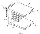
Фиг. 1 представляет собой пространственное изображение приводимого в качестве примера варианта предлагаемого многоконтактного, экранированного соединителя. Соединитель содержит вилочную часть 1 и розеточную 2 часть, которая установлена на схематично изображенной печатной плате 3 и соединена с ней. FIG. 1 is a perspective view of an exemplary embodiment of a multi-pin, shielded connector. The connector comprises a
Как лучше показано на фиг. 2, вилочная часть 1 содержит П-образный корпус 4, изготовленный из электроизоляционного материала. Штырьки 7 соединителя, размещенные в пересекающихся рядах, расположены в цокольной части 5 корпуса 4 параллельно стенкам 6, охватывающим розеточную часть 2. В этом варианте соединитель имеет четыре ряда и шесть колонок штырьков, хотя очевидно, что изобретение не ограничено этим частным примером и соединитель может иметь любое большее или меньшее число пересекающихся рядов и колонок. Цокольная часть 5 имеет выступы 8, каждый из которых охватывает соответствующий штырек и выступает наружу между стенками 6, при этом выступы образуют совместно с ответными углублениями или пазами розеточной части 2 режекторные элементы для борьбы с перекрестными помехами высокочастотных сигналов. As best shown in FIG. 2, the
Розеточная часть более подробно представлена на фиг. 3 и включает в себя корпус 9, изготовленный из электроизоляционного материала и выполненный ответным корпусу 4 вилочной части при размещении между стенками 6. Корпус 9 выполнен из промежуточных пластин 10 (см. фиг. 4), и крайних пластин 11 (фиг. 5). Пластины 10 и 11 выполнены таким образом, что каждая плоскость разъема между пластинами соответствует колонке штырьков 7 вилочной части 1. В рассматриваемом варианте розеточная часть 2 содержит пять промежуточных пластин 10 и две крайние пластины 11. The outlet part is presented in more detail in FIG. 3 and includes a housing 9 made of an insulating material and made mating to the
На фиг. 4 и 5 соответственно показаны конструкции пластин 10 и 11. Пластины выполнены аналогично с пазами 12, при этом крайние пластины 11 имеют пазы только с одной стороны, а промежуточные пластины 10 имеют пазы с обеих сторон. Крайние пластины 11 зеркально симметричны. В рассматриваемом варианте соединителя на пластинах 10 и 11 выполнены бурты или упоры 13, упирающиеся в печатную плату 3 при установке на ней розеточной части. В пластинах также имеются сквозные отверстия 14, с помощью которых пластины собирают на винтах или болтах или с использованием других средств крепления с образованием корпуса 9 розеточной части. In FIG. 4 and 5, respectively, the structures of the
Пазы 12 простираются на начальном участке от стороны пластин 10 и 11, обращенной к вилочной части 1 в направлении штырьков 7, и сопряжены криволинейными участками с участками этих пазов, обращенными к печатной плате 3. После сборки пластины 10 и 11 образуют розеточную часть 2, при этом обращенные друг к другу пазы 12 образуют каналы для установки контактных узлов 15 и контактных выводов или проводников 16, из которых показаны только один контактный узел и один контактный вывод в промежуточной пластине 10, а еще один контактный узел и один контактный вывод показаны вместе с двумя вариантами соответствующих штырьков 7 различного сечения на фиг. 4. Пазы 12 имеют такую форму, чтобы на участке 17, обращенном к вилочной части 1, они соответствовали выступам 8, образуя вместе с ними указанные режекторные элементы для борьбы с перекрестными помехами высокочастотных сигналов. В зоне, примыкающей к участку 17, пазы 12 имеют сужения 18, соответствующие штырькам 7 вилочной части соединителя. The
Для экранирования соединителя поверхности и вилочной 1 и розеточной 2 частей металлизированы, за исключением поверхностей 19 выступов 8, охватывающих соответствующие штырьки 7 вилочной части 1 соединителя. Металлизация также отсутствует на поверхностях пазов 12 от места расположения упорной поверхности 20 между участком 17 и сужением 18. Таким образом, поверхность элемента 17 также металлизирована. Поскольку пластины 10 и 11 розеточной части 2 электрически соединены друг с другом благодаря металлизации, розеточная часть полностью экранирована от внешних помех. В результате этой металлизации штырьки и контактные выводы также полностью экранированы от внешнего окружения. Розеточная часть 2 также соединена с шиной заземления, расположенной на краю печатной платы 3 через металлизированные поверхности пластин 10 и 11 розеточной части 2. Контакт между вилочной частью 1 и розеточной частью 2 происходит непосредственно в плоскости заземляющей шины благодаря тому, что металлизированные поверхности цокольной части 5 и внутренних сторон стенок 6 вилочной части скользят по ответным металлизированным поверхностям корпуса 9 розеточной части (см. фиг. 6). Здесь для простоты в розеточной части показаны только один контактный узел и один контактный вывод (см. фиг. 6). Эта фигура показывает, каким образом достигается электрический контакт между штырьками 7 и контактными узлами 15 и каким образом контактные выводы 16 соединены с печатной платой 3. Для улучшения контакта между металлизированными поверхностями отдельных участков, а также, соответственно, между пластинами 10 и 11 поверхности должны иметь насечку, например, шероховатость с целью обеспечения надежного контакта между ними. For shielding the connector, the surfaces of both the male 1 and female 2 parts are metallized, except for the
Выводы экранированы от внешнего воздействия в месте соединения между частями соединителя выступами 8 и ответными участками 17 пазов 12, образующими режекторные элементы, при этом эти поверхности находятся в электрическом контакте друг с другом благодаря металлизации. Шина заземления, расположенная между вилочной 1 и розеточной 2 частями, также может иметь электрическое соединение при удлинении одного или нескольких штырьков 7 по сравнению с остальными (не показано). В этом случае при стыковке частей соединителя устанавливается электрический контакт между контактными узлами 15 и заземляющим выводом 16 розеточной части 2. The findings are shielded from external influences at the junction between the parts of the connector by the
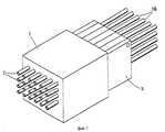
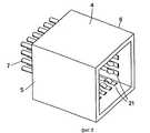
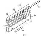
На фиг. 7 показан другой вариант реализации изобретения. Как показано на фиг. 8, вилочная часть 1 выполнена в виде корпуса 4 с коробчатой частью 6, полностью охватывающей розеточную часть 2. Как и в случае приведенного выше варианта, контактные штырьки 7 расположены в цокольной части 5 корпуса 4 и входят в пространство, образованное стенками 6, для контакта с розеточной частью. Для лучшего экранирования и электрического контакта между вилочной и розеточной частями внутренняя охватывающих элементов 6, т. е. их поверхности, обращенные к розеточной части 2, снабжена упругими металлическими лепестками 21, контактирующими с розеточной частью и улучшающими экранировку вокруг соединителя. Конструкция этих металлических лепестков и способ их крепления в вилочной части подробно описаны ниже и показаны на фиг. 10. При таком варианте реализации изобретения розеточная часть 2 является контактным узлом для подключения к множеству коаксиальных выводов 16 и выполнена, как описано выше, из промежуточных 10 и крайних 11 пластин, из которых на фиг. 9 показана только одна промежуточная пластина 10. Как и в описанном выше варианте, показан только один установленный контактный узел 15. Отличие этого вариант от описанного выше заключается в том, что в этом случае пазы 12 расположены поперек пластины и в них выполнены расширенные участки 22. Расширенные участки также металлизированы. В расширенном участке 22 экран жестко закреплен посредством металлической втулки 23, охватывающей коаксиальный вывод 16 и контактирующей с расширенным участком 22. In FIG. 7 shows another embodiment of the invention. As shown in FIG. 8, the
Для улучшения экранирования между вилочной и розеточной частями вилочную часть можно снабдить дополнительным заземляющим контактным узлом в виде тонкой металлической пластины 24 с отверстиями 25, ответными выступам 8. Лепестки 26 вырублены при образовании отверстий 25 и отогнуты перпендикулярно плоскости пластины для упора в выступы и обеспечения контакта с ответным участком 17 розеточной части. Выступы 8 имеют ответные пазы 27 для лепестков 26 (см. фиг. 10), где показана в разобранном виде вилочная часть с установленной в ней пластиной 24 и другими элементами. Для простоты показана только одна пластина, хотя в действительности требуются четыре пластины 24, на каждой из которых имеются вырубленные лепестки 26 с одной стороны отверстия 25, так как вырубить все четыре лепестка при образовании одного отверстия невозможно. Пластины размещены в вилочной части таким образом, чтобы лепестки упирались во все четыре стороны соответствующего выступа 8. To improve the shielding between the male and female parts, the male part can be equipped with an additional grounding contact node in the form of a
Описанные выше металлические лепестки 21 (см. фиг. 8) могут быть получены аналогично лепесткам 26 вырубкой металлических пластин с образованием отверстий, соответствующих выступам 8, при этом металлические пластины размещаются у цокольной части 5 вилочной части 1. При этом материал пластины за пределами цокольной части отогнут под прямым углом к плоскости пластины с образованием лепестков 21. В этом случае требуется только одна металлическая пластина. The
Понятно, что приведенные варианты реализации изобретения могут быть скомбинированы любым образом. Например, вилочная часть 1, показанная на фиг. 2, может быть также использована как розеточная часть, показанная на фиг. 7 и 9, а способ защиты от перекрестных помех, показанный на фиг. 10, и (или) экранирование, показанное на фиг. 8, могут быть избирательно использованы при необходимости в различных вариантах реализации изобретения. It is clear that the above embodiments of the invention can be combined in any way. For example, the
Очевидно, что изобретение не ограничивается приведенными вариантами реализации и в соответствии с формулой изобретения может быть видоизменено. Obviously, the invention is not limited to the above options for implementation and in accordance with the claims may be modified.
Claims (10)
Translated fromRussianApplications Claiming Priority (3)
| Application Number | Priority Date | Filing Date | Title |
|---|---|---|---|
| SE9004125-2 | 1990-12-21 | ||
| SE9004125ASE466126B (en) | 1990-12-21 | 1990-12-21 | MULTIPLE MULTIPLE SCREEN EQUIPMENT WITH COMMON EARTH |
| PCT/SE1991/000835WO1992011671A1 (en) | 1990-12-21 | 1991-12-05 | A multipolar screened connector having a common earth |
Publications (2)
| Publication Number | Publication Date |
|---|---|
| RU93050008A RU93050008A (en) | 1996-02-20 |
| RU2089978C1true RU2089978C1 (en) | 1997-09-10 |
Family
ID=20381295
Family Applications (1)
| Application Number | Title | Priority Date | Filing Date |
|---|---|---|---|
| RU9193050008ARU2089978C1 (en) | 1990-12-21 | 1991-12-05 | Shielded multipin connector with common grounding system |
Country Status (13)
| Country | Link |
|---|---|
| US (1) | US5354219A (en) |
| EP (1) | EP0651919B1 (en) |
| JP (1) | JPH06507267A (en) |
| AU (1) | AU648858B2 (en) |
| BR (1) | BR9107247A (en) |
| CA (1) | CA2098115C (en) |
| DE (1) | DE69120688T2 (en) |
| ES (1) | ES2092673T3 (en) |
| FI (1) | FI932669A0 (en) |
| NO (1) | NO932110L (en) |
| RU (1) | RU2089978C1 (en) |
| SE (1) | SE466126B (en) |
| WO (1) | WO1992011671A1 (en) |
Cited By (1)
| Publication number | Priority date | Publication date | Assignee | Title |
|---|---|---|---|---|
| RU2395881C1 (en)* | 2006-09-08 | 2010-07-27 | Сименс Энерджи Энд Отомейшн, Инк. | Devices and/or systems for connection of plc bus |
Families Citing this family (50)
| Publication number | Priority date | Publication date | Assignee | Title |
|---|---|---|---|---|
| US5380216A (en)* | 1992-05-11 | 1995-01-10 | The Whitaker Corporation | Cable backpanel interconnection |
| US5453016A (en)* | 1993-11-15 | 1995-09-26 | Berg Technology, Inc. | Right angle electrical connector and insertion tool therefor |
| EP0729653B1 (en)* | 1993-11-15 | 2001-05-16 | Berg Electronics Manufacturing B.V. | Right angle electrical connector and insertion tool |
| DE59401765D1 (en)* | 1994-03-03 | 1997-03-20 | Siemens Ag | Connectors for backplane wiring |
| EP0693795B1 (en)* | 1994-07-22 | 1999-03-17 | Berg Electronics Manufacturing B.V. | Selectively metallizized connector with at least one coaxial or twinaxial terminal |
| US5842872A (en)* | 1995-06-30 | 1998-12-01 | The Whitaker Corporation | Modular right angle board mountable coaxial connector |
| WO1997002629A1 (en)* | 1995-06-30 | 1997-01-23 | The Whitaker Corporation | Modular right-angle board mountable coaxial connector |
| JPH09139264A (en)* | 1995-11-13 | 1997-05-27 | Yazaki Corp | Multi-pole connector for PCB |
| US5833498A (en)* | 1995-12-28 | 1998-11-10 | Berg Technology, Inc. | Electrical connector having improved retention feature and receptacle for use therein |
| WO1997040554A1 (en)* | 1996-04-25 | 1997-10-30 | The Whitaker Corporation | A contact assembly for a coaxial connector |
| US6062911A (en)* | 1997-01-31 | 2000-05-16 | The Whitaker Corporation | Low profile power connector with high-temperature resistance |
| NL1012361C2 (en)* | 1999-06-16 | 2000-12-19 | Berg Electronics Mfg | Connector has contact elements mounted in housing, in which grooves extend transversely |
| WO2000077887A1 (en)* | 1999-06-16 | 2000-12-21 | Fci 's-Hertogenbosch B.V. | Connector, method for manufacturing such a connector and contact element for a connector |
| US6123586A (en)* | 1999-08-03 | 2000-09-26 | Hon Hai Precision Ind. Co., Ltd. | Modular connector |
| US6491545B1 (en)* | 2000-05-05 | 2002-12-10 | Molex Incorporated | Modular shielded coaxial cable connector |
| US6997762B2 (en)* | 2000-06-19 | 2006-02-14 | Intest Ip Corporation | Electrically shielded connector |
| US6910897B2 (en) | 2001-01-12 | 2005-06-28 | Litton Systems, Inc. | Interconnection system |
| US6979202B2 (en) | 2001-01-12 | 2005-12-27 | Litton Systems, Inc. | High-speed electrical connector |
| US6843657B2 (en) | 2001-01-12 | 2005-01-18 | Litton Systems Inc. | High speed, high density interconnect system for differential and single-ended transmission applications |
| US7018239B2 (en) | 2001-01-22 | 2006-03-28 | Molex Incorporated | Shielded electrical connector |
| EP1396051B1 (en) | 2001-06-13 | 2006-08-30 | Molex Incorporated | High-speed mezzanine connector |
| JP2003151690A (en)* | 2001-11-12 | 2003-05-23 | Hirose Electric Co Ltd | High speed transmission electrical connector |
| DE10318638A1 (en)* | 2002-04-26 | 2003-11-13 | Honda Tsushin Kogyo | Electrical HF connector without earth connections |
| WO2003094301A1 (en)* | 2002-05-06 | 2003-11-13 | Molex Incorporated | Differential signal connectors with esd protection |
| US6715357B2 (en)* | 2002-07-10 | 2004-04-06 | Texas Instruments Incorporated | Hermetic pressure transducer |
| US7549897B2 (en) | 2006-08-02 | 2009-06-23 | Tyco Electronics Corporation | Electrical connector having improved terminal configuration |
| US8142236B2 (en) | 2006-08-02 | 2012-03-27 | Tyco Electronics Corporation | Electrical connector having improved density and routing characteristics and related methods |
| US7670196B2 (en) | 2006-08-02 | 2010-03-02 | Tyco Electronics Corporation | Electrical terminal having tactile feedback tip and electrical connector for use therewith |
| US7753742B2 (en) | 2006-08-02 | 2010-07-13 | Tyco Electronics Corporation | Electrical terminal having improved insertion characteristics and electrical connector for use therewith |
| US7591655B2 (en) | 2006-08-02 | 2009-09-22 | Tyco Electronics Corporation | Electrical connector having improved electrical characteristics |
| US7976318B2 (en) | 2008-12-05 | 2011-07-12 | Tyco Electronics Corporation | Electrical connector system |
| US8157591B2 (en)* | 2008-12-05 | 2012-04-17 | Tyco Electronics Corporation | Electrical connector system |
| US8366485B2 (en) | 2009-03-19 | 2013-02-05 | Fci Americas Technology Llc | Electrical connector having ribbed ground plate |
| US8231415B2 (en) | 2009-07-10 | 2012-07-31 | Fci Americas Technology Llc | High speed backplane connector with impedance modification and skew correction |
| EP2290753B1 (en)* | 2009-08-31 | 2012-12-05 | ERNI Electronics GmbH | Connector and multilayer circuit board |
| US9472879B2 (en) | 2011-05-03 | 2016-10-18 | Cardioinsight Technologies, Inc. | High-voltage resistance of a connector interface |
| EP2624034A1 (en) | 2012-01-31 | 2013-08-07 | Fci | Dismountable optical coupling device |
| USD727268S1 (en) | 2012-04-13 | 2015-04-21 | Fci Americas Technology Llc | Vertical electrical connector |
| US8944831B2 (en) | 2012-04-13 | 2015-02-03 | Fci Americas Technology Llc | Electrical connector having ribbed ground plate with engagement members |
| US9257778B2 (en) | 2012-04-13 | 2016-02-09 | Fci Americas Technology | High speed electrical connector |
| USD727852S1 (en) | 2012-04-13 | 2015-04-28 | Fci Americas Technology Llc | Ground shield for a right angle electrical connector |
| USD718253S1 (en) | 2012-04-13 | 2014-11-25 | Fci Americas Technology Llc | Electrical cable connector |
| USD751507S1 (en) | 2012-07-11 | 2016-03-15 | Fci Americas Technology Llc | Electrical connector |
| US9543703B2 (en) | 2012-07-11 | 2017-01-10 | Fci Americas Technology Llc | Electrical connector with reduced stack height |
| USD745852S1 (en) | 2013-01-25 | 2015-12-22 | Fci Americas Technology Llc | Electrical connector |
| USD720698S1 (en) | 2013-03-15 | 2015-01-06 | Fci Americas Technology Llc | Electrical cable connector |
| US9466917B2 (en)* | 2014-06-16 | 2016-10-11 | Cooper Technologies Company | Hazardous location multi-pin connectors |
| JP6444775B2 (en)* | 2015-03-03 | 2018-12-26 | 富士通コンポーネント株式会社 | connector |
| FR3064826B1 (en)* | 2017-03-29 | 2020-10-09 | Tyco Electronics France Sas | SUPPORT KIT FOR PRESSURE FIT CONTACT PINS |
| CN110323622B (en)* | 2019-07-17 | 2024-07-19 | 上海航天科工电器研究院有限公司 | Radio frequency coaxial connector with special-shaped conductive structure and manufacturing method thereof |
Family Cites Families (9)
| Publication number | Priority date | Publication date | Assignee | Title |
|---|---|---|---|---|
| US4210376A (en)* | 1978-12-07 | 1980-07-01 | Amp Incorporated | Electrical connector receptacle |
| US4193654A (en)* | 1978-09-08 | 1980-03-18 | Amp Incorporated | Electrical connector receptacles |
| DE3362607D1 (en)* | 1982-09-07 | 1986-04-24 | Amp Inc | Electrical connector assembly for terminating flat shielded electrical cable |
| JPH0719632B2 (en)* | 1986-05-29 | 1995-03-06 | アンプ インコ−ポレ−テツド | Multi-pole shield connector |
| US4846727A (en)* | 1988-04-11 | 1989-07-11 | Amp Incorporated | Reference conductor for improving signal integrity in electrical connectors |
| US4975084A (en)* | 1988-10-17 | 1990-12-04 | Amp Incorporated | Electrical connector system |
| US5009616A (en)* | 1989-12-14 | 1991-04-23 | Amp Incorporated | Connector assembly with back shell having vanes |
| US5261829A (en)* | 1990-06-08 | 1993-11-16 | Fusselman David F | Connectors with ground structure |
| US5169343A (en)* | 1990-11-29 | 1992-12-08 | E. I. Du Pont De Nemours And Company | Coax connector module |
- 1990
- 1990-12-21SESE9004125Apatent/SE466126B/ennot_activeIP Right Cessation
- 1991
- 1991-12-05AUAU91090/91Apatent/AU648858B2/ennot_activeCeased
- 1991-12-05DEDE69120688Tpatent/DE69120688T2/ennot_activeExpired - Fee Related
- 1991-12-05BRBR9107247Apatent/BR9107247A/ennot_activeIP Right Cessation
- 1991-12-05JPJP4501786Apatent/JPH06507267A/enactivePending
- 1991-12-05USUS08/075,584patent/US5354219A/ennot_activeExpired - Fee Related
- 1991-12-05EPEP92901937Apatent/EP0651919B1/ennot_activeExpired - Lifetime
- 1991-12-05RURU9193050008Apatent/RU2089978C1/enactive
- 1991-12-05CACA002098115Apatent/CA2098115C/ennot_activeExpired - Fee Related
- 1991-12-05ESES92901937Tpatent/ES2092673T3/ennot_activeExpired - Lifetime
- 1991-12-05WOPCT/SE1991/000835patent/WO1992011671A1/enactiveIP Right Grant
- 1993
- 1993-06-09NONO93932110Apatent/NO932110L/enunknown
- 1993-06-11FIFI932669Apatent/FI932669A0/enunknown
Non-Patent Citations (1)
| Title |
|---|
| 1. DE, патент, N 1113973, кл. 21 с 21/01, 1964. 2. US, патент, N 4210376, кл. 339 - 17 LC, 1980. 3. US, патент, N 4193654, кл. 339-17, 1980.* |
Cited By (1)
| Publication number | Priority date | Publication date | Assignee | Title |
|---|---|---|---|---|
| RU2395881C1 (en)* | 2006-09-08 | 2010-07-27 | Сименс Энерджи Энд Отомейшн, Инк. | Devices and/or systems for connection of plc bus |
Also Published As
| Publication number | Publication date |
|---|---|
| EP0651919B1 (en) | 1996-07-03 |
| NO932110L (en) | 1993-08-17 |
| NO932110D0 (en) | 1993-06-09 |
| EP0651919A1 (en) | 1995-05-10 |
| US5354219A (en) | 1994-10-11 |
| AU648858B2 (en) | 1994-05-05 |
| CA2098115C (en) | 1997-03-11 |
| AU9109091A (en) | 1992-07-22 |
| SE9004125D0 (en) | 1990-12-21 |
| FI932669A7 (en) | 1993-06-11 |
| DE69120688T2 (en) | 1996-11-21 |
| FI932669A0 (en) | 1993-06-11 |
| BR9107247A (en) | 1994-04-05 |
| ES2092673T3 (en) | 1996-12-01 |
| SE9004125L (en) | 1991-12-16 |
| CA2098115A1 (en) | 1992-06-21 |
| JPH06507267A (en) | 1994-08-11 |
| WO1992011671A1 (en) | 1992-07-09 |
| DE69120688D1 (en) | 1996-08-08 |
| SE466126B (en) | 1991-12-16 |
Similar Documents
| Publication | Publication Date | Title |
|---|---|---|
| RU2089978C1 (en) | Shielded multipin connector with common grounding system | |
| US5525066A (en) | Connector for a cable for high frequency signals | |
| US4659163A (en) | Filtered shielded connector assembly | |
| US5238414A (en) | High-speed transmission electrical connector | |
| USRE39380E1 (en) | Electrical connector with protection for electrical contacts | |
| US6705902B1 (en) | Connector assembly having contacts with uniform electrical property of resistance | |
| US6439928B1 (en) | High density connector for balanced transmission lines | |
| US5961350A (en) | Modular side-by-side connectors | |
| RU2174275C2 (en) | Connecting block for high-speed data transmission | |
| US7074083B2 (en) | Connector assembly | |
| EP0677215B1 (en) | A connector with improved shielding | |
| EP0074205B1 (en) | A connector for coaxially shielded cable | |
| KR960702686A (en) | LOW PROFILE BACKSHELL / WIRING INTEGRATION AND INTERFACE SYSTEM | |
| US20020130728A1 (en) | Electrical connector and transmission line | |
| US6375506B1 (en) | High-density high-speed input/output connector | |
| US5013250A (en) | Multi-pole connector plug | |
| US6371810B1 (en) | Shielded connector arrangement having inner and outer shells | |
| US7273393B2 (en) | Connector shell for a multiple wire cable assembly | |
| CN109980471B (en) | Bus bar assembly | |
| EP0183772B1 (en) | Filtered shielded connector assembly | |
| JPH1140272A (en) | Connector with metal shell | |
| CN1846333B (en) | Connector housing for a multi-wire cable assembly | |
| TW202510433A (en) | Ground bus for a cable card assembly of an electrical connector | |
| JP2023184147A (en) | Cable assembly structure and connector | |
| EP0995239B1 (en) | Apparatus for forming a connection through a board |