RU2081442C1 - Multi-focus birefringence lens system - Google Patents
Multi-focus birefringence lens systemDownload PDFInfo
- Publication number
- RU2081442C1 RU2081442C1SU894613259ASU4613259ARU2081442C1RU 2081442 C1RU2081442 C1RU 2081442C1SU 894613259 ASU894613259 ASU 894613259ASU 4613259 ASU4613259 ASU 4613259ARU 2081442 C1RU2081442 C1RU 2081442C1
- Authority
- RU
- Russia
- Prior art keywords
- lens
- birefringent
- rays
- lens system
- forces
- Prior art date
Links
- 230000003287optical effectEffects0.000claimsabstractdescription53
- 239000000463materialSubstances0.000claimsabstractdescription6
- 230000000295complement effectEffects0.000claimsdescription7
- 238000004519manufacturing processMethods0.000abstractdescription3
- 239000000126substanceSubstances0.000abstractdescription3
- 230000000694effectsEffects0.000abstractdescription2
- 229920000642polymerPolymers0.000description8
- 230000010287polarizationEffects0.000description4
- 239000011521glassSubstances0.000description3
- 230000010355oscillationEffects0.000description3
- 230000004075alterationEffects0.000description2
- 239000003795chemical substances by applicationSubstances0.000description2
- 150000001875compoundsChemical class0.000description2
- 238000010276constructionMethods0.000description2
- 239000013078crystalSubstances0.000description2
- 210000003128headAnatomy0.000description2
- 230000001788irregularEffects0.000description2
- 229920003229poly(methyl methacrylate)Polymers0.000description2
- 229920000058polyacrylatePolymers0.000description2
- 239000004926polymethyl methacrylateSubstances0.000description2
- 210000001747pupilAnatomy0.000description2
- 239000013589supplementSubstances0.000description2
- 239000013598vectorSubstances0.000description2
- 229910021532CalciteInorganic materials0.000description1
- CERQOIWHTDAKMF-UHFFFAOYSA-MMethacrylateChemical compoundCC(=C)C([O-])=OCERQOIWHTDAKMF-UHFFFAOYSA-M0.000description1
- 238000013459approachMethods0.000description1
- 238000005452bendingMethods0.000description1
- 230000005540biological transmissionEffects0.000description1
- 238000010835comparative analysisMethods0.000description1
- 239000002131composite materialSubstances0.000description1
- 230000021615conjugationEffects0.000description1
- 210000004087corneaAnatomy0.000description1
- 230000003247decreasing effectEffects0.000description1
- 230000001419dependent effectEffects0.000description1
- 238000010586diagramMethods0.000description1
- 239000006185dispersionSubstances0.000description1
- 238000005516engineering processMethods0.000description1
- 230000004424eye movementEffects0.000description1
- -1for examplePolymers0.000description1
- 230000014759maintenance of locationEffects0.000description1
- 230000003278mimic effectEffects0.000description1
- 229920000620organic polymerPolymers0.000description1
- 239000010453quartzSubstances0.000description1
- 210000003786scleraAnatomy0.000description1
- VYPSYNLAJGMNEJ-UHFFFAOYSA-Nsilicon dioxideInorganic materialsO=[Si]=OVYPSYNLAJGMNEJ-UHFFFAOYSA-N0.000description1
- 230000001225therapeutic effectEffects0.000description1
- 230000007704transitionEffects0.000description1
- 238000012795verificationMethods0.000description1
Images


Classifications
- A—HUMAN NECESSITIES
- A61—MEDICAL OR VETERINARY SCIENCE; HYGIENE
- A61F—FILTERS IMPLANTABLE INTO BLOOD VESSELS; PROSTHESES; DEVICES PROVIDING PATENCY TO, OR PREVENTING COLLAPSING OF, TUBULAR STRUCTURES OF THE BODY, e.g. STENTS; ORTHOPAEDIC, NURSING OR CONTRACEPTIVE DEVICES; FOMENTATION; TREATMENT OR PROTECTION OF EYES OR EARS; BANDAGES, DRESSINGS OR ABSORBENT PADS; FIRST-AID KITS
- A61F2/00—Filters implantable into blood vessels; Prostheses, i.e. artificial substitutes or replacements for parts of the body; Appliances for connecting them with the body; Devices providing patency to, or preventing collapsing of, tubular structures of the body, e.g. stents
- A61F2/02—Prostheses implantable into the body
- A61F2/14—Eye parts, e.g. lenses or corneal implants; Artificial eyes
- A61F2/16—Intraocular lenses
- A61F2/1613—Intraocular lenses having special lens configurations, e.g. multipart lenses; having particular optical properties, e.g. pseudo-accommodative lenses, lenses having aberration corrections, diffractive lenses, lenses for variably absorbing electromagnetic radiation, lenses having variable focus
- A61F2/1616—Pseudo-accommodative, e.g. multifocal or enabling monovision
- A61F2/1618—Multifocal lenses
- G—PHYSICS
- G02—OPTICS
- G02B—OPTICAL ELEMENTS, SYSTEMS OR APPARATUS
- G02B13/00—Optical objectives specially designed for the purposes specified below
- A—HUMAN NECESSITIES
- A61—MEDICAL OR VETERINARY SCIENCE; HYGIENE
- A61F—FILTERS IMPLANTABLE INTO BLOOD VESSELS; PROSTHESES; DEVICES PROVIDING PATENCY TO, OR PREVENTING COLLAPSING OF, TUBULAR STRUCTURES OF THE BODY, e.g. STENTS; ORTHOPAEDIC, NURSING OR CONTRACEPTIVE DEVICES; FOMENTATION; TREATMENT OR PROTECTION OF EYES OR EARS; BANDAGES, DRESSINGS OR ABSORBENT PADS; FIRST-AID KITS
- A61F2/00—Filters implantable into blood vessels; Prostheses, i.e. artificial substitutes or replacements for parts of the body; Appliances for connecting them with the body; Devices providing patency to, or preventing collapsing of, tubular structures of the body, e.g. stents
- A61F2/02—Prostheses implantable into the body
- A61F2/14—Eye parts, e.g. lenses or corneal implants; Artificial eyes
- A61F2/16—Intraocular lenses
- A61F2/1613—Intraocular lenses having special lens configurations, e.g. multipart lenses; having particular optical properties, e.g. pseudo-accommodative lenses, lenses having aberration corrections, diffractive lenses, lenses for variably absorbing electromagnetic radiation, lenses having variable focus
- A61F2/1648—Multipart lenses
- G—PHYSICS
- G02—OPTICS
- G02B—OPTICAL ELEMENTS, SYSTEMS OR APPARATUS
- G02B3/00—Simple or compound lenses
- G02B3/10—Bifocal lenses; Multifocal lenses
- G—PHYSICS
- G02—OPTICS
- G02B—OPTICAL ELEMENTS, SYSTEMS OR APPARATUS
- G02B5/00—Optical elements other than lenses
- G02B5/30—Polarising elements
- G02B5/3083—Birefringent or phase retarding elements
- G—PHYSICS
- G02—OPTICS
- G02C—SPECTACLES; SUNGLASSES OR GOGGLES INSOFAR AS THEY HAVE THE SAME FEATURES AS SPECTACLES; CONTACT LENSES
- G02C7/00—Optical parts
- G02C7/02—Lenses; Lens systems ; Methods of designing lenses
- G—PHYSICS
- G02—OPTICS
- G02C—SPECTACLES; SUNGLASSES OR GOGGLES INSOFAR AS THEY HAVE THE SAME FEATURES AS SPECTACLES; CONTACT LENSES
- G02C7/00—Optical parts
- G02C7/02—Lenses; Lens systems ; Methods of designing lenses
- G02C7/024—Methods of designing ophthalmic lenses
- G02C7/028—Special mathematical design techniques
- G—PHYSICS
- G02—OPTICS
- G02C—SPECTACLES; SUNGLASSES OR GOGGLES INSOFAR AS THEY HAVE THE SAME FEATURES AS SPECTACLES; CONTACT LENSES
- G02C7/00—Optical parts
- G02C7/02—Lenses; Lens systems ; Methods of designing lenses
- G02C7/04—Contact lenses for the eyes
- G02C7/041—Contact lenses for the eyes bifocal; multifocal
- G02C7/042—Simultaneous type
- G—PHYSICS
- G02—OPTICS
- G02C—SPECTACLES; SUNGLASSES OR GOGGLES INSOFAR AS THEY HAVE THE SAME FEATURES AS SPECTACLES; CONTACT LENSES
- G02C7/00—Optical parts
- G02C7/02—Lenses; Lens systems ; Methods of designing lenses
- G02C7/04—Contact lenses for the eyes
- G02C7/049—Contact lenses having special fitting or structural features achieved by special materials or material structures
- G—PHYSICS
- G02—OPTICS
- G02C—SPECTACLES; SUNGLASSES OR GOGGLES INSOFAR AS THEY HAVE THE SAME FEATURES AS SPECTACLES; CONTACT LENSES
- G02C7/00—Optical parts
- G02C7/02—Lenses; Lens systems ; Methods of designing lenses
- G02C7/06—Lenses; Lens systems ; Methods of designing lenses bifocal; multifocal ; progressive
- G—PHYSICS
- G02—OPTICS
- G02C—SPECTACLES; SUNGLASSES OR GOGGLES INSOFAR AS THEY HAVE THE SAME FEATURES AS SPECTACLES; CONTACT LENSES
- G02C7/00—Optical parts
- G02C7/12—Polarisers
- A—HUMAN NECESSITIES
- A61—MEDICAL OR VETERINARY SCIENCE; HYGIENE
- A61F—FILTERS IMPLANTABLE INTO BLOOD VESSELS; PROSTHESES; DEVICES PROVIDING PATENCY TO, OR PREVENTING COLLAPSING OF, TUBULAR STRUCTURES OF THE BODY, e.g. STENTS; ORTHOPAEDIC, NURSING OR CONTRACEPTIVE DEVICES; FOMENTATION; TREATMENT OR PROTECTION OF EYES OR EARS; BANDAGES, DRESSINGS OR ABSORBENT PADS; FIRST-AID KITS
- A61F2/00—Filters implantable into blood vessels; Prostheses, i.e. artificial substitutes or replacements for parts of the body; Appliances for connecting them with the body; Devices providing patency to, or preventing collapsing of, tubular structures of the body, e.g. stents
- A61F2/02—Prostheses implantable into the body
- A61F2/14—Eye parts, e.g. lenses or corneal implants; Artificial eyes
- A61F2/16—Intraocular lenses
- A61F2002/16965—Lens includes ultraviolet absorber
- A61F2002/1699—Additional features not otherwise provided for
- G—PHYSICS
- G02—OPTICS
- G02C—SPECTACLES; SUNGLASSES OR GOGGLES INSOFAR AS THEY HAVE THE SAME FEATURES AS SPECTACLES; CONTACT LENSES
- G02C2202/00—Generic optical aspects applicable to one or more of the subgroups of G02C7/00
- G02C2202/16—Laminated or compound lenses
- G—PHYSICS
- G02—OPTICS
- G02C—SPECTACLES; SUNGLASSES OR GOGGLES INSOFAR AS THEY HAVE THE SAME FEATURES AS SPECTACLES; CONTACT LENSES
- G02C2202/00—Generic optical aspects applicable to one or more of the subgroups of G02C7/00
- G02C2202/22—Correction of higher order and chromatic aberrations, wave front measurement and calculation
Landscapes
- Health & Medical Sciences (AREA)
- Physics & Mathematics (AREA)
- Ophthalmology & Optometry (AREA)
- General Physics & Mathematics (AREA)
- Optics & Photonics (AREA)
- General Health & Medical Sciences (AREA)
- Vascular Medicine (AREA)
- Public Health (AREA)
- Transplantation (AREA)
- Engineering & Computer Science (AREA)
- Biomedical Technology (AREA)
- Heart & Thoracic Surgery (AREA)
- Cardiology (AREA)
- Life Sciences & Earth Sciences (AREA)
- Animal Behavior & Ethology (AREA)
- Oral & Maxillofacial Surgery (AREA)
- Veterinary Medicine (AREA)
- Mathematical Physics (AREA)
- Eyeglasses (AREA)
- Prostheses (AREA)
- Materials For Medical Uses (AREA)
- Lenses (AREA)
- Aerials With Secondary Devices (AREA)
- Investigating Or Analysing Materials By Optical Means (AREA)
- Testing Of Optical Devices Or Fibers (AREA)
Abstract
Description
Translated fromRussianИзобретение относится к многофокусной неахроматизированной или ахроматизированной многокомпонентной оптической линзовой системе и, в частности, к такой системе, в которой по меньшей мере одним из компонентов является двоякопреломляющая линза. The invention relates to a multifocal non-chromatic or achromatized multicomponent optical lens system and, in particular, to such a system in which at least one of the components is a birefringent lens.
В работе Осипова "Двойные поляризационные линзы", ж. Оптическая технология, том 40, N 5, страницы 277 279 (май 1979 г). /1/ описана двойная поляризационная линза, состоящая из плоско-выпуклой/плоско-вогнутой двоякопреломляющей линзовой системы. Эта линзовая система может комбинироваться с изотропной линзой с целью создания параллельного эталонного луча и сфокусированного сигнального луча, причем лучи поляризованы ортогонально, для использования в лазерной системе. In the work of Osipov, "Double polarizing lenses," g. Optical Technology, Volume 40, No. 5, pages 277,279 (May 1979). / 1 / a double polarization lens is described, consisting of a plano-convex / plano-concave birefringent lens system. This lens system can be combined with an isotropic lens to create a parallel reference beam and a focused signal beam, the rays being polarized orthogonally for use in a laser system.
Наиболее близкой к заявленной является линзовая система, известная из патента США N 37558201, /2/ включающая плоско-выпуклую/плоско-вогнутую двоякопреломляющую дуплетную линзу в комбинации с изотропной линзовой системой переменной силы. Система применяется при проверке глаз. Из сказанного следует, что двоякопреломляющие линзы используются прежде всего в плоско-выпуклых/плоско-вогнутых линзовых конструкциях. Такая конструкция комбинируется в одном случае, например, в соответствии с работой Осипова, с изотропной линзой с целью создания параллельного луча поляризованного света. Комбинация призматической двоякопреломляющей или призматической изотропной линзой используется в патенте Великобритании N 865361, для создания соседних изображений предмета с целью проверки глаза. Кроме того, конструкция систем, где каждая система включает в себя двоякопреломляющую линзу и средство управления для ориентации поляризационной плоскости, предлагались в качестве систем с изменяемым фокусным расстоянием в различных патентах. Closest to the claimed is the lens system, known from US patent N 37558201, / 2 / comprising a flat-convex / flat-concave birefringent doublet lens in combination with an isotropic variable-force lens system. The system is used when checking eyes. It follows from the above that birefringent lenses are primarily used in plano-convex / plano-concave lens designs. This design is combined in one case, for example, in accordance with the work of Osipov, with an isotropic lens in order to create a parallel beam of polarized light. The combination of a prismatic birefringent or prismatic isotropic lens is used in UK Patent No. 865361 to create adjacent images of an object for eye examination. In addition, systems design, where each system includes a birefringent lens and control means for orienting the polarization plane, have been proposed as variable focal length systems in various patents.
Однако в этой системе невозможно, по крайней мере, два фокуса выбрать полностью независимыми друг от друга. However, in this system it is impossible to select at least two focuses completely independent from each other.
В описанных аналогах неорганические кристаллы кварца и кальцита упомянуты в качестве материалов двоякопреломляющих линз. Двойное преломление также может быть свойственно для некоторых типов органических полимеров. Существуют полимеры, которые проявляют высокую двоякопреломляемость и имитируют оптические свойства одноосевых кристаллов. Такие двоякопреломляющие полимеры предложены для применения с изотропными слоями в многослойных светопроводящих и поляризационных устройствах. In the described analogues, inorganic crystals of quartz and calcite are mentioned as materials of birefringent lenses. Birefringence may also be characteristic of some types of organic polymers. There are polymers that exhibit high birefringence and mimic the optical properties of uniaxial crystals. Such birefringent polymers are proposed for use with isotropic layers in multilayer light-conducting and polarizing devices.
Тот факт, что многие полимеры могут быть двоякопреломляющими, например, под действием напряжений, является известным. Вся область анализа фотоупругости и напряжений с помощью поляризованного света основана на этом явлении. Также известно, что при растягивании полимера за пределы его диапазона упругости, двоякопреломляемость может привести к необратимости полимера. The fact that many polymers can be birefringent, for example, under stress, is known. The entire field of analysis of photoelasticity and stress using polarized light is based on this phenomenon. It is also known that when the polymer is stretched beyond its elastic range, birefringence can lead to irreversibility of the polymer.
Технической задачей изобретения является создание многофокусной, например, бифокальной, трифокальной, квадрофокальной и т.д. неахроматизированной или ахроматизированной двоякопреломляющей линзовой системы, в которой по меньшей мере два фокуса выбираются полностью независимыми друг от друга. An object of the invention is the creation of multifocal, for example, bifocal, trifocal, quadrofocal, etc. a non-chromatic or achromatized birefringent lens system in which at least two foci are selected to be completely independent of each other.
Другой задачей изобретения является создание многофокусной неахроматизированной или ахроматизированной двоякопреломляющей линзовой системы, имеющей минимум нежелательных фокусов или сил. Another objective of the invention is the creation of a multifocal non-chromatic or achromatized birefringent lens system having a minimum of undesirable tricks or forces.
Еще одной задачей изобретения является создание многофокусной неахроматизированной или ахроматизированной двоякопреломляющей линзовой системы, в которой по меньшей мере одной линзовой поверхности придается форма вне зависимости от физических параметров используемой среды при изготовлении компонент линзы и вне зависимости от заданных фокусов. Another objective of the invention is the creation of a multifocal non-chromatic or achromatized birefringent lens system in which at least one lens surface is shaped regardless of the physical parameters of the medium used in the manufacture of the lens components and regardless of the specified foci.
Также задачей изобретения является создание глазных линз, в частности, очковых линз, контактных линз и внутриокулярных линз, основанных на неахроматизированных или ахроматизированных двоякопреломляющих линзовых системах. It is also an object of the invention to provide ophthalmic lenses, in particular eyeglass lenses, contact lenses and intraocular lenses based on non-chromatic or achromatized birefringent lens systems.
Технический результат достигается тем, что многофокусная двоякопреломляющая линзовая система, содержащая первую линзовую компоненту, представляющую двоякопреломляющую линзу, имеющую две оптические силы Д2o и Д2e, и вторую линзовую компоненту, смежную с первой линзовой компонентой, причем вторая линзовая компонента представляет собой изотропную линзу, имеющую оптическую силу Д, при условии, что из результирующих оптических сил двоякопреломляющей линзовой системы, результирующие оптические силы по существу представляют D + D2о и D + D2e, значения Da и Db задаются независимо от свойств материала линзовых компонент, представляет собой глазную линзовую систему, и кривизны противолежащих поверхностей первой и второй линзовых компонент являются по существу идентичными или дополняющими, и что любая одна поверхность первой и второй линзовых компонент может быть задана с кривизной независимо от независимых оптических сил (Da и Db).The technical result is achieved in that a multifocal birefringent lens system comprising a first lens component representing a birefringent lens having two optical forces D2o and D2e and a second lens component adjacent to the first lens component, the second lens component being an isotropic lens, having an optical power D, provided that of the resulting optical forces of the birefringent lens system, the resulting optical forces essentially represent D + D2o and D + D2e , s The beginnings Da and Db are defined independently of the material properties of the lens components, is an ophthalmic lens system, and the curvatures of the opposite surfaces of the first and second lens components are essentially identical or complementary, and that any one surface of the first and second lens components can be defined with curvature independent of independent optical forces (Da and Db ).
Термин "смежный", используемый в отношении относительного расположения первой и второй линзовой компонент двоякопреломляющей линзовой системы в данном случае включает в себя случай, когда такие компоненты находятся в непосредственном взаимном контакте на значительной части противостоящих поверхностей, то есть, "составная линза" или "линзовое соединение" по определению, а также случай, когда такие противостоящие поверхности разделены коротким расстоянием вдоль их общей оси, обычно расстоянием в несколько миллиметров или меньше. The term “adjacent” used with respect to the relative position of the first and second lens components of the birefringent lens system in this case includes the case when such components are in direct mutual contact on a significant part of the opposing surfaces, that is, a “compound lens” or “lens connection "by definition, as well as the case when such opposing surfaces are separated by a short distance along their common axis, usually a distance of several millimeters or less.
Выражение "по существу идентичные или дополняющие", относящееся к кривизне противостоящих поверхностей первой и второй линзовых компонент многофокусной неахроматической двоякопреломляющей линзовой системы, употребленное здесь, необходимо понимать так, что если бы такие поверхности располагались бы контактно друг с другом, они бы стыковались в каждой точке вдоль взаимной границы раздела. Таким образом, например, в случае по существу идентичных величин кривизны эти величины кривизны были присущи плоскости, то есть поверхности имели бы бесконечный радиус кривизны, а в случае дополняющей кривизны такие поверхности представляли бы собой, например, сопряжение выпуклых и вогнутых поверхностей. The expression "essentially identical or complementary", referring to the curvature of the opposing surfaces of the first and second lens components of the multifocal non-chromatic birefringent lens system, used here, it is necessary to understand so that if such surfaces would be in contact with each other, they would dock at each point along the mutual interface. Thus, for example, in the case of essentially identical values of curvature, these values of curvature were inherent in the plane, that is, surfaces would have an infinite radius of curvature, and in the case of complementary curvature, such surfaces would be, for example, a conjugation of convex and concave surfaces.
Выражение "составная линза" или "линзы в комплекте" необходимо понимать в данном контексте как линзовую систему, содержащую по меньшей мере две линзовые составляющие, причем две противостоящие линзовые поверхности смежных линзовых компонент являются по существу идентичными или дополняющими так, что обе линзовые компоненты могут склеиваться вместе вдоль их противостоящих поверхностей, например, в плоско-выпуклой/плоско-вогнутой линзовой системе. Эти определения также приложимы для линзовой системы, в которой противостоящие линзовые поверхности разделены некоторыми расстоянием с целью подгонки одного или более оптических устройство, отличных от линзы, например, поляризационного средства. The term “compound lens” or “lenses in a set” is to be understood in this context as a lens system containing at least two lens components, the two opposing lens surfaces of adjacent lens components being essentially identical or complementary so that both lens components can adhere together along their opposing surfaces, for example, in a plano-convex / plano-concave lens system. These definitions also apply to a lens system in which opposing lens surfaces are separated by a distance to fit one or more optical devices other than a lens, such as a polarizing device.
Выражение "контактирующие линзы" необходимо понимать в данном контексте как относящиеся к линзовой системе, содержащей по меньшей мере две линзовые компоненты, причем эта линзовая удовлетворяет существенно требованию, что оптическая сила линзовой системы равна сумме оптических сил линзовых компонент. The expression "contacting lenses" must be understood in this context as referring to a lens system containing at least two lens components, and this lens meets the essential requirement that the optical power of the lens system is equal to the sum of the optical powers of the lens components.
Термин "неахроматизированный" необходимо понимать как относящийся к линзе или линзовой системе, которая проявляет одну или более сил, которые зависят от длины волны сфокусированного света (то есть, используемого) из-за дисперсности двоякопреломляющей и/или изотропной оптической среды, используемой при изготовлении линзы или линзовой системы. The term “non-chromatic” should be understood as referring to a lens or lens system that exerts one or more forces that depend on the wavelength of the focused light (that is, used) due to the dispersion of the birefringent and / or isotropic optical medium used in the manufacture of the lens or lens system.
Термин "ахроматизированный" должен пониматься как относящийся к линзовой системе, которая имеет одну или более сил, при одной из которых по меньшей мере проявляется диоптрийная величина, которая является постоянной по меньшей мере для двух различных волн сфокусированного (то есть использованного) света. The term “achromatic” should be understood as referring to a lens system that has one or more forces, at least one of which exhibits a diopter value that is constant for at least two different waves of focused (that is, used) light.
Изобретение поясняется чертежами, где представлено следующее:
на фиг.1 схематическое изображение двоякопреломляющей линзовой системы в соответствии с изобретением;
на фиг.2 схематическое изображение двуякопреломляющей линзовой компоненты, которая должна вставляться в линзовую систему по данному изобретению;
на фиг.3, 4 и 5 схематические изображения различных других примеров реализации двоякопреломляющей линзовой системы в соответствии с данным изобретением;
на фиг. 6 схематическое изобретение двоякопреломляющей линзовой системы по данному изобретению в комбинации с поляризационными средствами;
на фиг.7 схематические изображения соответственно видов спереди и сбоку очковых линз, содержащих двоякопреломляющую линзовую систему в соответствии с данным изобретением.The invention is illustrated by drawings, which show the following:
figure 1 is a schematic illustration of a birefringent lens system in accordance with the invention;
FIG. 2 is a schematic illustration of a birefringent lens component that is to be inserted into the lens system of this invention;
figure 3, 4 and 5 schematic representations of various other examples of the implementation of the birefringent lens system in accordance with this invention;
in FIG. 6 is a schematic invention of the birefringent lens system of this invention in combination with polarizing agents;
7 is a schematic diagram, respectively, of front and side views of spectacle lenses containing a birefringent lens system in accordance with this invention.
Все известные двоякопреломляющие линзовые системы обладают оптической осью (то есть, осью внутри кристаллической двоякопреломляющей среды), которая перпендикулярна оси линзы. Таким образом, двоякопреломляющая линзовая система имеет два частных коэффициента преломления, nо (для обычных колебаний или лучей) и nе (для необычных колебаний или лучей), но только для конкретного случая, когда e-лучи пересекают двоякопреломляющую линзу в направлении, которое является перпендикулярным, то есть ортогональным оптической оси. Для всех двух направлений e-лучи обладают эффективным коэффициентом преломления nе эфф, который является величиной, находящейся между nо и nе. В этом случае невозможно предсказать с какой-либо точностью оптическое качество или поведение двоякопреломляющей линзовой системы для e-лучей.All known birefringent lens systems have an optical axis (i.e., an axis within a crystalline birefringent medium) that is perpendicular to the axis of the lens. Thus, a birefringent lens system has two partial refractive indices, nо (for ordinary vibrations or rays) and ne (for unusual vibrations or rays), but only for the specific case when e-rays cross the birefringent lens in a direction that is perpendicular, that is, orthogonal to the optical axis. For all two directions, e-rays have an effective refractive index ne eff, which is a value between nо and nе . In this case, it is impossible to predict with any accuracy the optical quality or behavior of the birefringent lens system for e-rays.
С этой точки зрения может оказаться желательным использовать бифокальную линзовую систему, имеющую две независимо выбранные силы (или фокусы), с дополнительным отличием, заключающимся в том, что e-лучи пересекают двоякопреломляющую линзу в направлении, которое является исключительно перпендикулярным оптической оси. Случай, когда все e-лучи пересекают двоякопреломляющую линзу в ортогональном направлении к оптической оси будет называться "идеальной геометрией" двоякопреломляющей линзовой системы. From this point of view, it may be desirable to use a bifocal lens system having two independently selected forces (or foci), with the additional difference that the e-rays cross the birefringent lens in a direction that is exclusively perpendicular to the optical axis. The case where all e-rays intersect a birefringent lens in the orthogonal direction to the optical axis will be called the "ideal geometry" of the birefringent lens system.
На фиг. 1 показан один пример двоякопреломляющей линзовой системы с идеальной геометрией, имеющей изотропную линзовую компоненту 1, обладающую сферическими поверхностями R1 и R2, и изотропную линзовую компоненту 2, имеющую сферические поверхности R3 и R4 впереди и позади двоякопрелопляющей линзовой компоненты 3, обладающей дополнительными сферическим поверхностями R2 и R3, причем жирная стрелка показывает ее оптическую ось (так же будет в случае всех последующих рисунков). Предположим, что заданы силы (определяющие и соответствующие фокусы) Da и Db линзовой системы, причем следующие ограничения относятся к бифокальной линзовой системе с идеальной геометрией:
D34 + Dо + D12 Da (1а)
D34 + De + D12 Db(1b)
и ограничение "идеальной геометрии":
где D12 и D34 являются силами передней и задней изотропных линзовых компонент соответственно, а Do и De являются силами двоякопреломляющих линзовых компонент для o-лучей и е-лучей.In FIG. 1 shows one example of a birefringent lens system with ideal geometry having an
D34 + Do + D12 Da (1a)
D34 + De + D12 Db (1b)
and the restriction of "ideal geometry":
where D12 and D34 are the forces of the front and rear isotropic lens components, respectively, and Do and De are the forces of birefringent lens components for o-rays and e-rays.
Для примера с идеальной геометрией годится отношение
или
De m • Do
где
При этом бифокальная линзовая система, показанная на фиг.1, с идеальной геометрией описывается следующим:

D34 Da Do D12
Если, например, радиус R3 является выбранным заранее, тогда R2 может быть вычислен из уравнений (6a) или (6b). Тогда на основании вычисленного радиуса R2 и равенства (2) можно определить радиус R1, а с помощью заданного радиуса R3 и уравнения (7) можно вычислить R4. В принципе может задаваться любой из четырех радиусов.For an example with ideal geometry, the relation
or
De m • Do
Where
In this case, the bifocal lens system shown in Fig. 1, with ideal geometry, is described as follows:
D34 Da Do D12
If, for example, the radius R3 is preselected, then R2 can be calculated from equations (6a) or (6b). Then, based on the calculated radius R2 and equality (2), we can determine the radius R1, and using the given radius R3 and equation (7), we can calculate R4. In principle, any of four radii can be specified.
В более общем случае реализации неидеальной геометрии двоякопреломляющей линзовой системы e-колебания пересекают двоякопреломляющую линзу в направлении, которое необязательно является перпендикулярным оптической оси. Таким образом, e-лучи обладают своими эффективными коэффициентами преломления nе, эфф в пределах между nе и nо. Поскольку на эффективные коэффициенты nе эфф, ни траектории e-лучей в пределах двоякопреломляющей линзы заранее не известны, причем траектории и эффективные коэффициенты nе эфф являются взаимно зависимыми, о действительном функционировании линзой системы, включающей двоякопреломляющую линзу, невозможно судить непосредственно по величинам nе и геометрии линзы.In a more general case of imperfect geometry of a birefringent lens system, e-vibrations intersect the birefringent lens in a direction that is not necessarily perpendicular to the optical axis. Thus, e-rays have their effective refractive indices ne , eff in the range between ne and nо . Since the effective coefficients ne eff and the trajectories of e-rays within the birefringent lens are not known in advance, and the trajectories and effective coefficients ne eff are mutually dependent, it is impossible to judge the actual functioning of the system of the system including the birefringent lens directly by the values of ne and lens geometry.
Разумное вычисление работы двоякопреломляющих линз должно основываться на подробной записи световых лучей через такую линзу. Такая запись световых лучей включает в себя определение пространственных составляющих векторов распространения света перед и после произвольной ориентации границы перехода между изотропной и двоякопреломляющей средой. A reasonable calculation of the operation of birefringent lenses should be based on a detailed recording of light rays through such a lens. Such a recording of light rays includes determining the spatial components of the light propagation vectors before and after an arbitrary orientation of the transition boundary between an isotropic and birefringent medium.
При данном выборе или ориентации оптической оси двоякопреломляющей среды это определение включает в себя построение Гюйгенса, то есть общий случай построения тангенциальной плоскости на эллиптическом тороиде, смотрите, например, Дж. Стронг: "Концепции классической оптики", страница 138, В.Х. Фримен и компания (1958 г.). With this choice or orientation of the optical axis of the birefringent medium, this definition includes the Huygens construction, that is, the general case of constructing a tangential plane on an elliptic toroid, see, for example, J. Strong: "Concepts of Classical Optics", page 138, V.Kh. Freeman and Company (1958).
На основании этих вычислений построения лучей, которые также приложимы и для o-лучей, практически все интересующие данные о работе линзы силы линз, резкость изображения, хроматическая и сферическая аберрация могут выявить свои значения. За счет включений формул Френеля для переданной амплитуды света, пересекающего границу между двумя оптическими средами, можно также определить переданную интенсивность многослойной линзы. Based on these calculations of the construction of rays, which are also applicable to o-rays, almost all data of interest on the operation of a lens, lens power, image sharpness, chromatic and spherical aberration can reveal their values. Due to the inclusion of Fresnel formulas for the transmitted amplitude of the light crossing the boundary between two optical media, the transmitted intensity of the multilayer lens can also be determined.
Примеры двоякопреломляющей линзы неправильной геометрии в соответствии с данным изобретением далее приведены на фиг.2-5. В этих примерах использованы следующие определения:
Величина Определение
DVO Обратная сила у вершины для о-лучей из обычных вычислений обратной силы у вершины.Examples of a birefringent lens of irregular geometry in accordance with this invention are further illustrated in FIGS. 2-5. The following definitions are used in these examples:
Value Definition
DVO Vertex retroactive force for o-rays from conventional vertex retroactive force calculations.
DVE Обратная сила у вершины для е-лучей из обычных вычислений обратной силы у вершины. DVE Vertex retroactive force for e-rays from conventional vertex retroactive force calculations.
DO Обратная сила у вершины для о-лучей из вычислений траектории лучей. DO The inverse force at the vertex for o-rays from ray path calculations.
DE Обратная сила у вершины для е-лучей из вычислений траектории лучей. DE The inverse force at the vertex for e-rays from ray path calculations.
ACM "Мера остроты", то есть отношение между площадью минимальной фокусной точки и площадью (то есть сечением) линзы. ACM A "measure of sharpness," that is, the ratio between the area of the minimum focal point and the area (i.e. cross section) of the lens.
Величина определение
PTR Процент средней переданной интенсивности от падающей интенсивности, связанной с силой.Magnitude definition
PTR Percentage of average transmitted intensity of incident intensity associated with force.
no Коэффициент преломления двоякопреломляющей линзы для о-лучей. no Refractive index of a birefringent lens for o-rays.
ne Коэффициент преломления двоякопреломляющей линзовой компоненты для е-лучей в случае, когда е-лучи является перпендикулярными оптической оси. ne The refractive index of the birefringent lens component for e-rays in the case where e-rays are perpendicular to the optical axis.
n12 Коэффициент преломления изотропной линзовой компоненты, имеющей радиусы R1 и R2.n12 The refractive index of an isotropic lens component having radii R1 and R2.
n34 Коэффициент преломления изотропной линзовой компоненты, имеющей радиусы R3 и R4.n34 The refractive index of an isotropic lens component having radii R3 and R4.
гамма Угол между оптической осью и осью линзы. gamma The angle between the optical axis and the axis of the lens.
альфа Угол между лучами падающего света и осью линзы. alpha The angle between the rays of the incident light and the axis of the lens.
Величина Определение
альфар Угол между плоскостью, образованной лучами падающего света, и осью линзы и плоскостью, образованной оптической осью двоякопреломляющей линзовой компонент, и осью линзы.Value Definition
alphap The angle between the plane formed by the incident light rays and the axis of the lens and the plane formed by the optical axis of the birefringent lens component and the axis of the lens.
R1, R2, R3 и R4 Радиусы поверхностей сферических линз линзовой системы, показанной на фиг. 2 5. R1, R2, R3 and R4 The radii of the surfaces of the spherical lenses of the lens system shown in FIG. 2 5.
d Диаметр линзовой системы. d Diameter of the lens system.
C12, C23 и C34 Толщина у центров линз линзовой системы, показанной на фиг. 2 5. C12, C23 and C34 The thickness at the centers of the lenses of the lens system shown in FIG. 2 5.
DF Обратное расстояние (в диоптриях) между фокальной точкой и центром обратной поверхности линзовой системы. DF The reciprocal distance (in diopters) between the focal point and the center of the back surface of the lens system.
Dpr Призматическая сила в призматических диоптриях (1 призматическая диоптрия=1 см девиации на метр). Dpr Prismatic force in prismatic diopters (1 prismatic diopter = 1 cm deviation per meter).
Конструктивные размеры двоякопреломляющей линзовой компоненты 3, показанной на фиг. 2, следующие:
Радиус передней поверхности R2=7,5 мм
Радиус задней поверхности R3=7,8 мм
Толщина в центре C23=0,05 мм
Диаметр линзовой системы d=6 мм
Ориентация оптической оси гамма=90o
Коэффициенты преломления no=1,443, ne=1,8
Направление падающего света альфа r=0o
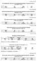
В табл. 1А приведены результаты вычислений величины для о-лучей двоякопреломляющей линзовой компоненты,показанной на фиг.2.The structural dimensions of the
Radius of the front surface R2 = 7.5 mm
Radius of the rear surface R3 = 7.8 mm
Thickness at center C23 = 0.05 mm
The diameter of the lens system d = 6 mm
Orientation of the optical axis gamma = 90o
Refractive indices no = 1,443, ne = 1,8
Direction of incident light alpha r = 0o
In the table. 1A shows the results of calculations of the magnitude for the o-rays of the birefringent lens component shown in FIG.
Приведенные данные показывают, что действительные обратные силы у вершины DO и DE оказываются больше, чем соответствующие величины DVO и DVE. Это происходит из-за того, что ненулевая апертура входящего светового пучка. Действительно, может быть показано, что падающий свет с нулевой апертурой DO и DVO полностью согласуется, а DE и DVE почти совпадают. Для случая падающего по оси света оба фокальных пятна располагаются точно на оси линзы. Необходимо отметить, что резкость изображения е-лучей является отличной по сравнению с резкостью о-лечей. Потери на передачу для е-лучей больше, чем для о-лучей, потому что е-лучи отклоняются с большей степенью, чем о-лучи. The data presented show that the real reverse forces at the vertices DO and DE are greater than the corresponding values of DVO and DVE. This is due to the non-zero aperture of the incoming light beam. Indeed, it can be shown that incident light with a zero aperture of DO and DVO is completely consistent, while DE and DVE are almost the same. In the case of incident along the axis of light, both focal spots are located exactly on the axis of the lens. It should be noted that the sharpness of the image of e-rays is excellent compared with the sharpness of o-heal. Transmission losses for e-rays are greater than for o-rays, because e-rays are deflected to a greater extent than o-rays.
В двоякопреломляющей линзовой системе, показанной на фиг. 3А и 3В, двоякопреломляющая линзовая компонента 3, показанная на фиг. 2, скомбинирована с изотропными линзовыми компонентами 1 и 2. Единственное различие между этими двумя линзовыми системами заключается в ориентации оптической оси двоякопреломляющей линзовой компоненты 2, которая является по существу перпендикулярной оси линзы на фиг. 3В. Параметры линзы для обеих линзовых систем выбирают такими, чтобы линзовые системы являлись практически афокальными для обычных лучей (то есть они обладают нулевой силой) и чтобы они проявляли положительную силу для е-лучей. Эти параметры являются следующими:
Радиусы R1 7,85мм R2 7,5мм R3 7,8мм R4 7,8мм
Толщина в центре C12 0,04мм C23 0,05мм C34 0,03мм
Диаметр линзовой системы ///7 d 6мм
Среда линзы n12 1,443 no 1,443, ne 1,8 - n34 1,443
Ориентация падающего света гамма 90o
Направление падающего света альфаr oo
В табл.2А приведены результаты вычислений для о-лучей двоякопреломляющей линзовой компатенты на фиг.3А.In the birefringent lens system shown in FIG. 3A and 3B, the
Radii R1 7.85mm R2 7.5mm R3 7.8mm R4 7.8mm
Thickness at center C12 0.04mm C23 0.05mm C34 0.03mm
Diameter of the lens system /// 7 d 6mm
Lens medium n12 1,443 no 1,443,
Orientation of incident light gamma 90o
Direction of incident light alphar oo
Table 2A shows the calculation results for the o-rays of the birefringent lens component in FIG. 3A.
В табл.2В приведены результаты вычислений величины для е-лучей двоякопреломляющей линзовой компаненты на фиг.3А. Table 2B shows the results of calculations of the magnitude for the e-rays of the birefringent lens component in FIG. 3A.
И снова для всех падающих лучей, параллельных оси линзы, фокальные пятна оба располагаются точно на оси линзы. Переданная интенсивность е-лучей повысилась по сравнению со случаем с единственной двоякопреломляющей линзой (фиг. 2), но резкость немного ухудшилась. And again, for all incident rays parallel to the axis of the lens, the focal spots are both located exactly on the axis of the lens. The transmitted e-ray intensity increased compared to the case with a single birefringent lens (Fig. 2), but the sharpness worsened slightly.
На фиг. 3А показана работа линзовой системы для случая, когда имеется свет, падающий вне оси. Рассмотрение вычислений, перечисленных в приводимых ниже таблицах 4 и 5, ограничивается е-лучами, поскольку о-лучи ведут себя так же, как и известные изотропные линзы. In FIG. 3A shows the operation of the lens system for the case when there is light incident off the axis. The consideration of the calculations listed in tables 4 and 5 below is limited to e-rays, since o-rays behave in the same way as known isotropic lenses.
Во-первых данные для случая пучка падающих световых лучей, при которых угол между плоскостью падения и оптической осью двоякопреломляющей линзовой составляющей равен нулю, представлены ниже в табл.3. Firstly, the data for the case of a beam of incident light rays, at which the angle between the plane of incidence and the optical axis of the birefringent lens component is zero, are presented below in Table 3.
Исходя из этих данных можно сделать вывод, что двоякопреломляющая линзовая системы по данному изобретению проявляет эффективную силу DF, которая практически идентична силе DVE для света, падающего по оси. С точки зрения конструкции линзы такая характеристика может оказаться выгодной, например в случае глазной линзы и, в частности, контактной линзы, когда может быть желательно поддерживать ту же самую эффективную силу независимо от угла падающего света относительно оси линзы даже, если произойдут некоторые потери разности изобретения. Based on these data, it can be concluded that the birefringent lens system of this invention exhibits an effective DF power that is almost identical to the DVE power for light incident along the axis. From the point of view of the lens design, such a characteristic may prove advantageous, for example, in the case of an eye lens and, in particular, a contact lens, when it may be desirable to maintain the same effective force regardless of the angle of incident light relative to the axis of the lens, even if some loss of the difference of the invention occurs .
Во-вторых, данные о работе этой линзовой системы для лучей света, падающие вне оси, когда оптическая ось является перпендикулярной плоскости падающего света, представлены в табл.4. Secondly, the data on the operation of this lens system for light rays incident off the axis when the optical axis is perpendicular to the plane of incident light are presented in Table 4.
Сравнительный анализ для падающих лучей этого типа показывает, что двоякопреломляющая линзовая система по данному изобретению работает очень похоже с изотропной линзовой системой с идентичной силой DVE. Например, практическое следствие этого заключается в том, что конструкция контактной линзы базируется на стандартных оптических соотношениях и свойствах, остающихся по существу верным для данной двоякопреломляющей линзовой системы и данного типа падающего света. A comparative analysis for incident rays of this type shows that the birefringent lens system of this invention works very similarly with an isotropic lens system with identical DVE power. For example, the practical consequence of this is that the design of the contact lens is based on standard optical ratios and properties that remain essentially true for a given birefringent lens system and this type of incident light.
Комбинированные данные, взятые из табл.4 и 3, указывают, что в случае бифокальной контактной линзы дополнение для чтения обеспечивается предпочтительно за счет е-лучей, а дополнение для дальнего рассмотрения обеспечивается предпочтительно о-лучами. Эти же данные также указывают на то, что оптическая ось бифокальной контактной линзы должна быть сориентирована в направлении, которое является по существу вертикальным, когда поле зрения понимается как горизонтальное, например, слева направо. И, наоборот, когда зрение рассматривается в основном в вертикальном направлении, данные фиг. 3 и 4 указывают, что направление оптической оси бифокальной контактной линзы должно быть по существу горизонтальным. The combined data taken from Tables 4 and 3 indicate that in the case of a bifocal contact lens, the reading supplement is preferably provided by e-rays, and the supplement for further consideration is preferably provided by o-rays. The same data also indicate that the optical axis of the bifocal contact lens should be oriented in a direction that is essentially vertical when the field of view is understood as horizontal, for example, from left to right. Conversely, when vision is seen mainly in the vertical direction, the data of FIG. 3 and 4 indicate that the direction of the optical axis of the bifocal contact lens should be substantially horizontal.
Как указывалось выше, только одна двоякопреломляющая линзовая компонента и одна изотропная линзовая компонента требуется с целью создания двух независимо заданных сил. Однако, может оказаться выгодным создать для конкретных случаев трех- или более линзовую систему. Однако такая линзовая система, предлагаемая по данному изобретению и схематически показанная на фиг. 3А, содержит склеральную контактную линзу, в которой двоякопреломляющая линзовая компонента 3, диаметр которой соответствует максимальному диаметру зрачка, вводится в заделанном виде в изотропной линзовой компоненте, диаметр которой соответствует диаметру склеры. Изотропная линзовая компонента впереди и позади двоякопреломляющей линзовой компоненты соответственно 1 и 2 могут рассматриваться как две изотропные линзовые компоненты всей линзовой системы. As indicated above, only one birefringent lens component and one isotropic lens component are required in order to create two independently specified forces. However, it may be advantageous to create for specific cases a three- or more lens system. However, such a lens system of the invention and shown schematically in FIG. 3A comprises a scleral contact lens in which a
Различные компоненты могут изготавливаться из одного и того же или различных оптических материалов. Например, двоякопреломляющий полимер типа одного из описанных в приведенных патентах или ориентированный полимер, например, полиметилметакрилат, который вытянут, может комбинироваться с любым известным изотропным материалом контактной линзы типа гидрометилметакрилата или (невытянутого) полиметилметакрилата для создания бифокальной контактной линзы в соответствии с данным изобретением. Different components can be made from the same or different optical materials. For example, a birefringent polymer such as one of those described in the cited patents or an oriented polymer, for example, polymethyl methacrylate that is stretched, can be combined with any known isotropic contact lens material such as hydromethyl methacrylate or (unstretched) polymethyl methacrylate to create a bifocal contact lens in accordance with this invention.
На фиг.4 показана другая двоякопреломляющая линзовая система в соответствии с данным изобретением, обладающая следующими параметрами конструкции для двоякопреломляющей линзовой компоненты 3 и изотропной линзовой компоненты 2. Figure 4 shows another birefringent lens system in accordance with this invention, having the following design parameters for
Радиусы R2 38 мм R3 50 мм R4 -50 мм
Толщина у центра C23 0,2 мм C34 1,0 мм
Диаметр линзовой системы d 6 мм
Среда линзы no 1,443, ne 1,8 n34 1,443
Ориентация оптической оси гамма 90o
Направление падающего света альфаr 0o.Radii R2 38 mm R3 50 mm R4 -50 mm
Thickness at center C23 0.2 mm C34 1.0 mm
Diameter of the
Lens medium no 1,443,
Orientation of the optical axis gamma 90o
Direction of incident light alphar 0o .
Приведенные результаты в табл.5А и 5В указывают, что двоякопреломляющие линзовые системы по данному изобретению могут применяться в качестве бифокальных внутриглазных линз. The results in tables 5A and 5B indicate that the birefringent lens systems of this invention can be used as bifocal intraocular lenses.
Как показа на фиг.3,B, двоякопреломляющие линзовые системы в соответствии с данным изобретением являются бифокальными для ориентации оптической оси, отличных от перпендикулярной также к оси линзы. As shown in FIG. 3, B, the birefringent lens systems of the present invention are bifocal for orienting the optical axis other than also perpendicular to the axis of the lens.
Как можно заметить из приведенных табл.6А, 6В и расчетов, сила, связанная с e-лучами, уменьшалась. Это происходило потому, что эффективные коэффициенты преломления ne эфф меньше, чем в случае гамма 90o. Поэтому только в немногих случаях можно использовать другие углы между осями оптической и линзы, отличные от гамма 90o.As can be seen from the above tables 6A, 6B and calculations, the force associated with e-rays decreased. This was because the effective refractive indices ne eff are less than in the case of gamma 90o . Therefore, only in few cases can you use other angles between the axes of the optical and the lens, other than gamma 90o .
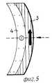
Однако, в лучшем случае только при малых отклонениях гамма от 90o работа линзы может оказаться удовлетворительной. Поэтому изобретением предусмотрено сгибание листа двоякопреломляющего полимера, оптическая ось которого лежит в плоскости листа так, что образует цилиндрическую поверхность, причем ось цилиндра является перпендикулярной к получившейся кольцевой оптической оси. Радиус цилиндра, может, например, быть задан с величиной, которая соответствует одному из радиусов двоякопреломляющей линзы. Анализ такой линзы показывает, что она будет работать почти идентично линзе, у которой оптическая ось перпендикулярна оси линзы по всей линзе. Как это является очевидным, аппроксимация сближается с увеличивающимся радиусом цилиндра.However, in the best case, only with small deviations of gamma from 90o the lens operation can be satisfactory. Therefore, the invention provides for bending a sheet of a birefringent polymer, the optical axis of which lies in the plane of the sheet so as to form a cylindrical surface, the axis of the cylinder being perpendicular to the resulting annular optical axis. The radius of the cylinder, for example, can be set with a value that corresponds to one of the radii of the birefringent lens. An analysis of such a lens shows that it will work almost identically to a lens whose optical axis is perpendicular to the axis of the lens throughout the lens. As this is obvious, the approximation approaches the increasing radius of the cylinder.
В описанных выше примерах было показано, что двоякопреломляющая линзовая компонента комбинируется с одной или более изотропными линзовыми компонентами с целью создания двух различных сил, величины которых могут выбираться независимо друг от друга даже при остающемся неизменным геометрическом параметре составной линзовой системы. В случае, например, контактной линзы этот свободный параметр подходит для конструкции кривизны задней поверхности линзовой системы. В общем случае этот эффект может также достигаться за счет сочетания двух двоякопреломляющих линзовых компонент. Для обеспечения только двух сил угол между оптической осью двоякопреломляющих линз должен быть 90o, так, чтобы о-лучи в первой двоякопреломляющей линзе были бы e-лучами во второй и наоборот. Такая конструкция, которая может быть названа линзовой системой "с пересекающимся двоякопреломлением", показана на фиг.5.In the examples described above, it was shown that a birefringent lens component is combined with one or more isotropic lens components in order to create two different forces, the values of which can be selected independently from each other even with the geometric parameter of the composite lens system remaining unchanged. In the case of, for example, a contact lens, this free parameter is suitable for constructing the curvature of the rear surface of the lens system. In general, this effect can also be achieved by combining two birefringent lens components. To ensure only two forces, the angle between the optical axis of the birefringent lens should be 90o , so that the o-rays in the first birefringent lens would be e-rays in the second and vice versa. Such a design, which may be called the lens system "intersecting birefringence," is shown in Fig.5.
Конструктивные параметры линзовой системы, показанной на фиг.5 состоящей из двоякопреломляющих линзовых компонентов 3 и 4, суть следующие:
Радиус передней поверхности 7,9 мм
Радиус промежуточной поверхности 7,5 мм
Радиус задней поверхности 7,8мм
Толщина в центре, первая линза 0,06 мм
Толщина в центре, вторая линза 0,06 мм
Диаметр линзовой системы 6,0 мм
Оптическая среда,
первая линза no=1,443, ne=1,8,
вторая линза no 1,443, ne 1,8.The design parameters of the lens system shown in Fig. 5, consisting of
Front Radius 7.9 mm
Intermediate surface radius 7.5 mm
7.8mm Radius
Thickness in the center, first lens 0.06 mm
Thickness in the center, second lens 0.06 mm
Diameter of the lens system 6.0 mm
Optical medium
the first lens no = 1,443, ne = 1,8,
the second lens is no 1,443,
Ориентация оптических осей гамма1=гамма2=90o
Угол между оптическими осями 90o
Направление падающего света альфаr 0o
В расчете, данном в табл.7, следующие величины имеют значения:
Величина Значение
DOE Сила, связанная с o-лучами в первой и с e-лучами во второй линзе
DEO Сила, связанная с o-лучами в первой и с o-лучами во второй линзе.Orientation of the optical axes gamma1 = gamma2 = 90o
Angle between optical axes 90o
Direction of incident light alphar 0o
In the calculation given in table 7, the following values have values:
Value Meaning
DOE Strength associated with o-rays in the first and e-rays in the second lens
DEO Strength associated with o-rays in the first and o-rays in the second lens.
DVOE и DVEO Соответствующие силы, полученные на основании обычных вычислений у задней вершины
Резкость изображения, обеспечиваемая линзовой системой, показанной на фиг. 5, имеет тот же порядок величины для падающего на ось света, как и в случае изотропно-двоякопреломляющей линзовой системы, например, показанной на фиг.3А.DVOE and DVEO Corresponding forces obtained from conventional calculations at the rear peak
The image sharpness provided by the lens system shown in FIG. 5 has the same order of magnitude for the incident light on the axis, as in the case of an isotropically birefringent lens system, for example, shown in FIG. 3A.
Конструкция с перекрестным двоякопреломлением могут создавать большие разности силы для обоих ортогонально поляризованных возникающих световых колебаний даже при очень тонких линзах. В соответствии с этим такие конструкции могут применяться для контактных линз. Cross-birefringence designs can create large power differences for both orthogonally polarized emerging light vibrations even with very thin lenses. Accordingly, such designs can be used for contact lenses.
В представленных вариантах показано, что двоякопреломляющая линзовая система в соответствии с данным изобретением может успешно применяться в качестве лечебной контактной линзы для или в качестве внутриглазной линзы, когда требуются по меньшей мере две различные силы: по меньшей мере одна при дальнем рассмотрении и по меньшей мере одна для чтения. In the presented embodiments, it is shown that the birefringent lens system in accordance with this invention can be successfully used as a therapeutic contact lens for or as an intraocular lens when at least two different forces are required: at least one upon further examination and at least one for reading.
Примеры реализации данных двоякопреломляющих линзовых систем могут также служить в качестве лечебных очковых линз или встраиваться в них. Предпочтительный вариант реализации такой линзы показан на фиг.7,A и 7,B, где позицией 5 обозначена бифокальная часть двоякопреломляющей линзы, например, с двоякопреломляюще-изотропной линзовой системой для чтения и дальнего рассматривания, а позицией 6 обозначена однофокусная линзовая часть для дальнего рассматривания, изготовленная из обычной среды. В очковой линзе, показанной на фиг. 7, A и 7,B, сила, соответствующая o-лучам линзовой части 5, идентична силе линзовой части 6. Преимущественно изотропное вещество, используемое в частях 5 и 6, является везде однородным, например, полиакрилатом, а двоякопреломляющая линзовая компонента части 5, является растянутым полиакрилатом. Examples of the implementation of these birefringent lens systems can also serve as medical lenses or integrate into them. A preferred embodiment of such a lens is shown in FIGS. 7, A and 7, B, where 5 denotes the bifocal part of the birefringent lens, for example, with a birefringent isotropic lens system for reading and long-distance viewing, and 6 denotes a single-focus lens part for long viewing made from ordinary medium. In the eyeglass lens shown in FIG. 7, A and 7, B, the force corresponding to the o-rays of the
Для чтения используются падающие на ось лучи света, то есть движение глаза является таким, чтобы поддерживалась прямая линия (а именно, ось линзы) между считываемым текстом и зрачком. При таком движении глаза обычно не производится движение головы. Обычное расстояние при чтении от глаз до текста составляет около 40 см, и печатные тексты обычно в ширину составляют 20 см слева направо. For reading, rays of light incident on the axis are used, that is, the eye movement is such that a straight line (namely, the axis of the lens) between the read text and the pupil is maintained. With this movement of the eye, the head usually does not move. The usual reading distance from the eyes to the text is about 40 cm, and printed texts are usually 20 cm wide from left to right.
Следовательно, во время считывания горизонтально отпечатанных текстов ось глазной линзы не выходит за пределы угла примерно 30o. Линза очков обычно располагается в 12 мм от роговой оболочки.Therefore, during the reading of horizontally printed texts, the axis of the ophthalmic lens does not extend beyond an angle of about 30° . The lens of the glasses is usually located 12 mm from the cornea.
Поэтому зона очковой линзы, которая обеспечивает силу для чтения, не должна быть больше примерно 1 см в горизонтальном направлении. В любом случае дополнительная зона чтения может быть не шире 2 см. В вертикальном направлении дополнительная зона для чтения составляет всего около 1 1,5 см. Зона может преимущественно располагаться в нижней части очковой линзы, как показано на примере реакции фиг. 7,A и 7,B. Therefore, the area of the spectacle lens that provides reading power should not be greater than about 1 cm in the horizontal direction. In any case, the additional reading zone may not be wider than 2 cm. In the vertical direction, the additional reading zone is only about 1 1.5 cm. The zone can preferably be located at the bottom of the eyeglass lens, as shown by the reaction of FIG. 7, A and 7, B.
Применение двоякопреломляющей бифокальной линзовой системы в пределах такой дополнительной зоны для чтения позволяет получить решающее преимущество по сравнению с обычными двухзонными бифокальными очковыми линзами, в которых каждая из двух зон является однофокусной. Хотя изложенные соображения относительно необходимых размеров дополнительной зоны для чтения также подошли бы к обычным бифокальным очковым линзам, такие линзы обычно проявляют значительно большие дополнительные зоны для чтения. В основном это происходит из-за того, что обычные очковые линзы с такой небольшой зоной большей силы были бы косметически непривлекательными. The use of a birefringent bifocal lens system within such an additional reading zone provides a decisive advantage over conventional dual-zone bifocal lenses in which each of the two zones is single-focus. Although the foregoing considerations regarding the required size of the additional reading area would also be suitable for conventional bifocal eyeglass lenses, such lenses usually exhibit significantly larger additional reading areas. This is mainly due to the fact that ordinary spectacle lenses with such a small area of greater strength would be cosmetically unattractive.
Двоякопреломляющие линзовые системы при сравнении имеют вид однофокусных линз, что означает, что дополнительная зона для чтения является неразличимой в зоне видимости, в частности, если, как было отмечено выше, двоякопреломляющая линза имеет коэффициент преломления nо, который идентичен коэффициенту преломления, используемому в линзе для дальнейшего рассматривания. В противоположность этому гораздо меньшая дополнительная зона для чтения может обеспечиваться довольно большой силой для чтения в линзе скромной толщины, что может позволить снизить общий вес очковых линз. И, наконец, необходимо отметить, что двоякопреломляющая линзовая система обеспечивает получение заданных сил одновременно для ближнего и дальнего рассматривания.When compared, birefringent lens systems look like single-focus lenses, which means that the additional reading area is indistinguishable in the field of view, in particular, if, as noted above, the birefringent lens has a refractive index nо that is identical to the refractive index used in the lens for further consideration. In contrast, a much smaller additional reading area can be provided by a fairly large reading power in a modest-thickness lens, which can reduce the overall weight of spectacle lenses. And, finally, it should be noted that the birefringent lens system provides the specified forces at the same time for close and long viewing.
Поэтому поле зрения проходит за пределы всей площади очковой линзы, что является важным в случае, когда дальнее видение необходимо в направлении вниз, или, например, когда удаленные объекты рассматриваются в лежачем положении. С помощью имеющихся в настоящее время бифокальных очков для того, чтобы посмотреть поверх дополнительной зоны чтения, необходимо значительно наклонить голову вперед. Therefore, the field of view extends beyond the entire area of the eyeglass lens, which is important in the case when far vision is necessary in the downward direction, or, for example, when distant objects are viewed in a supine position. With the help of the currently available bifocal glasses, in order to look over the additional reading zone, you must significantly tilt your head forward.
Как отмечено выше, обе силы двоякопреломляющей линзы системы создаются за счет обоих ортогонально поляризованных колебаний света. Если, например, сила дальнего рассматривания связана со световым колебанием в вертикальной поляризационной плоскости, а сила чтения со световым колебанием с горизонтальной плоскостью поляризации, солнечные очки, содержащие поляризационные фильтры, могут с успехом применяться для выбора исключительно каждой из обеих имеющихся сил в зависимости от направления взгляда. Такие солнечные очки могли бы, например, содержать поляризационный фильтр, который создает вертикально поляризационный свет в большей зоне для дальнейшего рассмотрения и поляризационный фильтр, который создает горизонтально поляризованный свет в меньшей зоне для чтения. As noted above, both forces of the birefringent lens of the system are created due to both orthogonally polarized light oscillations. If, for example, the power of long-range viewing is associated with light oscillation in the vertical polarization plane, and the reading force with light oscillation with the horizontal plane of polarization, sunglasses containing polarizing filters can be successfully used to select exclusively each of both available forces depending on the direction sight. Such sunglasses could, for example, comprise a polarizing filter that creates vertically polarized light in a larger reading area and a polarizing filter that creates horizontally polarized light in a smaller reading area.
Распределение зоны дальнего рассматривания и зоны чтения будет соответствовать распределению, очевидному из фиг. 7А. С помощью таких солнечных очков внефокусное задержание света из-за ближней силы устраняется при силе дальнего рассматривания и, наоборот, при этом не происходит потеря яркости по сравнению с яркостью света, получаемой в обычных солнечных поляризационных очках, то есть, по существу 50% яркости подающего света будет в каждом из обоих фокусов. Физический внешний вид солнечных очков такой конструкции не отличается от обычных поляризационных солнечных очков, будучи косметически удачным. The distribution of the far viewing zone and reading zone will correspond to the distribution obvious from FIG. 7A. With the help of such sunglasses, out-of-focus light retention due to near-field power is eliminated with long-range viewing power and, conversely, there is no loss of brightness compared to the brightness of light obtained in ordinary solar polarized glasses, that is, essentially 50% of the brightness of the feed there will be light in each of both tricks. The physical appearance of sunglasses of this design does not differ from ordinary polarized sunglasses, being cosmetically successful.
Если оптические оси двух двоякопреломляющих линз не находятся под углом 90o, то в общем случае будет четыре различные силы, потому что и о-сила и е-сила первой линзы сочетаются с о-силой и е-силой второй линзы. В линзовой системе, показанной на фиг. 5, обе дополняющие силы должны быть -0,51 и -0,47 диоптрий, то есть линза практически является трифокальной.If the optical axes of two birefringent lenses are not at an angle of 90o , then in general there will be four different forces, because both the o-force and e-force of the first lens are combined with the o-force and e-force of the second lens. In the lens system shown in FIG. 5, both complementary forces should be -0.51 and -0.47 diopters, that is, the lens is practically trifocal.
При хорошей аппроксимации сила линзы задается (смотри Дж. Стронг, указанное выше, стр. 319):
D (n 1) • S
где D есть сила,
n есть коэффициент преломления,
S есть так называемый "коэффициент формы" линзы. Уравнение (8) может также применяться для случая двоякопреломляющей линзы неправильной геометрии (например, фиг. 3, А, 4 и 5). С точки зрения уравнения (8) силы D1о и D1e первой линзы для о-лучей и е-лучей заданы в виде:
D1o (n10 1) • S1(9а)
D1e (n1e 1)o S2(9в)
D1e m • D1o(9с)
где
и где n1e и n1o являются коэффициентами преломления первой линзы для е-лучей и о-лучей соответственно. Аналогичные соотношения применимы и для второй линзы.With a good approximation, the strength of the lens is set (see J. Strong, cited above, p. 319):
D (n 1) • S
where D is power
n is the refractive index
S is the so-called "shape factor" of the lens. Equation (8) can also be applied to the case of a birefringent lens of irregular geometry (for example, Fig. 3, A, 4 and 5). From the point of view of equation (8), the forces D1o and D1e of the first lens for o-rays and e-rays are given in the form:
D1o (n10 1) • S1 (9a)
D1e (n1e 1)o S2 (9c)
D1e m • D1o (9s)
Where
and where n1e and n1o are the refractive indices of the first lens for e-rays and o-rays, respectively. Similar ratios apply to the second lens.
Обобщая полученные результаты, можно прийти к выводу:
(1) Одиночная двоякопреломляющая линза данного вещества проявляет две различные одновременные силы; только одна из двух сил может быть данной заранее выбранной величиной, причем вторая сила является функцией этой заранее заданной величины.Summarizing the results obtained, we can conclude:
(1) A single birefringent lens of a given substance exhibits two different simultaneous forces; only one of the two forces can be a given predetermined quantity, the second force being a function of this predetermined quantity.
(2) Линзовая система, состоящая из двоякопреломляющей линзовой компоненты и изотропной, проявляет две силы, каждая из которых может выбираться заранее в полной независимости одна от другой. (2) A lens system consisting of a birefringent lens component and isotropic exhibits two forces, each of which can be preselected in complete independence from one another.
Двоякопреломляющие линзы и линзовые системы позволяют приписывать различные интенсивности различными силами. При обслуживании соотношений интенсивности необходимо, во-первых, отметить, что амплитуда естественного падающего света векторно разделена, то есть амплитуда Ao и Ae, связанные соответственно с о-лучами и е-лучами, имеют каждая величину:
где A есть амплитуда падающего света.Birefringent lenses and lens systems make it possible to attribute different intensities with different forces. When servicing the intensity ratios, it is necessary, firstly, to note that the amplitude of natural incident light is vector separated, that is, the amplitudes Ao and Ae associated with o-rays and e-rays, respectively, have each value:
where A is the amplitude of the incident light.
Отсюда следует, что 50% имеющейся интенсивности направлено к каждому из двух фокусов. It follows that 50% of the available intensity is directed to each of the two tricks.
Поэтому отношение между интенсивностями сфокусированного находящегося вне фокусах света составляет 1:1 в каждом из двух фокусов. Это очень хорошо сравнивается с другими известными бифокальными линзовыми конструкциями одновременного рассматривания, о которых говорилось выше. Therefore, the ratio between the intensities of the focused out-of-focus light is 1: 1 in each of the two foci. This compares very well with other known bifocal lens designs of simultaneous viewing, which were mentioned above.
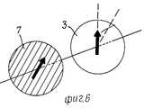
Это отношение может быть любой величиной, если линейно поляризованный свет падает на линзовую систему, содержащую по меньшей мере одну двоякопреломляющую линзу. На фиг. 6 схематически показана двоякопреломляющая линзовая система, в которой относительная ориентация оптической оси двоякопреломляющей линзовой компоненты 3 по отношению к плоскости вибрации падающего поляризованного света характеризуется углом бета. Поляризованный свет производится поляризующим средством 7. Интенсивности Iо и Iе, связанные с о- и с e-лучами соответственно, заданы в виде:
Io Ip sin2 бета(11а)
Ie Ip cos2 бета(11в)
где Ip является интенсивностью падающего поляризованного света.This ratio can be any value if linearly polarized light is incident on the lens system containing at least one birefringent lens. In FIG. 6 schematically shows a birefringent lens system in which the relative orientation of the optical axis of the
Io Ip sin2 beta (11a)
Ie Ip cos2 beta (11c)
where Ip is the intensity of the incident polarized light.
С точки зрения уравнения (II) ясно, что соотношение между Io и Ie может задаваться в виде любой величины за счет точного выбора угла бета. Если для создания поляризованного света используется общий поляризационный фильтр, это может быть получено, как отмечается, с потерей общей интенсивности. Но в определенных случаях может оказаться более важным снизить в одной силе интенсивность находящегося вне фокуса света, чем иметь более высокие, но равные интенсивности, связанные с общими силами.From the point of view of equation (II) it is clear that the ratio between Io and Ie can be set in the form of any value due to the exact choice of the angle beta. If a common polarizing filter is used to create polarized light, this can be obtained, as noted, with a loss of overall intensity. But in certain cases, it may be more important to reduce the intensity of the out-of-focus light in one force than to have higher, but equal intensities associated with common forces.
Приведенные соображения в общем случае приложимы для двоякопреломляющих линзовых систем, то есть для систем, включающих в себя, например, две пересекающиеся двоякопреломляющие линзовые компоненты (фиг. 5) или линзовых систем, включающих в себя одну двоякопреломляющую и одну или более изотропных линзовых компонентов (фиг. 3,A, 3, B и 4). The above considerations are generally applicable for birefringent lens systems, that is, for systems including, for example, two intersecting birefringent lens components (FIG. 5) or lens systems including one birefringent and one or more isotropic lens components (FIG. . 3, A, 3, B, and 4).
Интенсивности, связанные с четырьмя силами двоякопреломляющей линзовой системы в соответствии с фиг. 7, заданы в виде:
I (OO) (1/2) • cos2 бета12(12а)
I (OE) (1/2) • sin2 бета12(12в)
I (EO) (1/2) • sin2 бета12(12с)
I (EE) (1/2) • cos2 бета12(12о)
где I (OO) является интенсивностью, связанной с о-лучами в первой и е-лучами во второй двоякопреломляющей линзе и так далее. "I" есть интенсивность падающего неполяризованного света, а бета12 есть угол между оптическими связями обеих двоякопреломляющих компонент.The intensities associated with the four forces of the birefringent lens system in accordance with FIG. 7 are given in the form:
I (OO) (1/2) • cos2 beta12 (12a)
I (OE) (1/2) • sin2 beta12 (12v)
I (EO) (1/2) • sin2 beta12 (12s)
I (EE) (1/2) • cos2 beta12 (12 °)
where I (OO) is the intensity associated with the o-rays in the first and e-rays in the second birefringent lens and so on. “I” is the intensity of the incident unpolarized light, and beta12 is the angle between the optical bonds of both birefringent components.
Из уровня 12 следует, что определенная степень свободы существует при придании интенсивностей различным силам. Если, например, линзовая система изготовлена трифокальной с равными интенсивностями при всех трех силах, тогда для случая D10 D20, описанного выше, угол бета12 определяют следующим образом:
I (OO) + I (EE) I (OE) I (EO)(13)
или
cos2 бета12 (sin2 бета12)/2(13')
что приводит к следующему
бета12 54,7o(14)
Для другого возможного случая D10 D20, указанного выше, угол между обеими оптическими осями должен быть
бета12 35,3o(15)
Многофокусные двоякопреломляющие линзовые системы, которые являются ахроматическими или которые проявляют заданную величину хроматической аберрации.From level 12 it follows that a certain degree of freedom exists when giving intensities to various forces. If, for example, the lens system is made trifocal with equal intensities for all three forces, then for the case D10 D20 described above, the angle beta12 is determined as follows:
I (OO) + I (EE) I (OE) I (EO) (13)
or
cos2 beta12 (sin2 beta12 ) / 2 (13 ')
leading to the following
beta12 54.7o (14)
For another possible case of D10 D20 above, the angle between both optical axes should be
beta12 35.3o (15)
Multifocal birefringent lens systems that are achromatic or that exhibit a given amount of chromatic aberration.
Многофокусные линзовые системы, выполненные в соответствии с данным изобретением, которые включают в себя одну или более двоякопреломляющих и одну или изотропную линзовую компоненту, могут быть также ахроматизированы до изменяющейся степени. Следующие по ахроматизирующим линзовым системам являются соразмерными с формализмом, как например, в книге М. Херцбергера "Учебник по физике", МакГроу-Хилл, 1967 г. стр. 6 42. Проверка Херцбергером ахроматизма немного отличается от более часто применяемой теории, например, представленной в указанной выше Дж. Стронга, стр. 319, или М. Борна "Оптика", Шпрингер-Ферлаг, 1972 г. стр. 82. Кроме того, необходимо отметить, что для последующего описания ахроматизированных двоякопреломляющих линзовых систем требуется, что отдельные компоненты были "близки" друг к другу в соответствии с определением этого термина, данным выше, но в отличие от описанных выше неахроматизированных линзовых систем, то есть фиг. 1, 3, B, и 4 в них не требуется наличие двух противостоящих линзовых поверхностей с идентичной или дополняющей кривизной. Multifocal lens systems made in accordance with this invention, which include one or more birefringent and one or isotropic lens component, can also be achromatized to a varying degree. The following achromatizing lens systems are commensurate with formalism, as, for example, in M. Herzberger’s book "Physics Textbook", McGraw-Hill, 1967, p. 6 42. Herzberger's verification of achromatism is slightly different from the more commonly used theory, for example, presented in the aforementioned J. Strong, p. 319, or M. Bourne, “Optics,” Springer-Ferlag, 1972, p. 82. In addition, it should be noted that the subsequent description of achromatic birefringent lens systems requires that the individual components were "close" to each other to a friend in accordance with the definition of this term given above, but in contrast to the non-chromatic lens systems described above, i.e., FIG. 1, 3, B, and 4, they do not require two opposing lens surfaces with identical or complementary curvature.
Claims (1)
Translated fromRussianApplications Claiming Priority (3)
| Application Number | Priority Date | Filing Date | Title |
|---|---|---|---|
| US10077387A | 1987-09-24 | 1987-09-24 | |
| US07/226,669US4981342A (en) | 1987-09-24 | 1988-08-01 | Multifocal birefringent lens system |
| US226669 | 1988-08-01 |
Publications (1)
| Publication Number | Publication Date |
|---|---|
| RU2081442C1true RU2081442C1 (en) | 1997-06-10 |
Family
ID=26797531
Family Applications (1)
| Application Number | Title | Priority Date | Filing Date |
|---|---|---|---|
| SU894613259ARU2081442C1 (en) | 1987-09-24 | 1989-01-17 | Multi-focus birefringence lens system |
Country Status (20)
| Country | Link |
|---|---|
| US (2) | US4981342A (en) |
| EP (1) | EP0308705B1 (en) |
| JP (1) | JP2881439B2 (en) |
| KR (1) | KR0124540B1 (en) |
| CN (1) | CN1017830B (en) |
| AT (1) | ATE155588T1 (en) |
| AU (1) | AU607539B2 (en) |
| BR (1) | BR8804905A (en) |
| CA (1) | CA1323221C (en) |
| CZ (1) | CZ282242B6 (en) |
| DD (1) | DD283466A5 (en) |
| DE (1) | DE3855963T2 (en) |
| ES (1) | ES2106720T3 (en) |
| FI (1) | FI95842C (en) |
| HU (1) | HU208584B (en) |
| IL (1) | IL87704A (en) |
| NO (1) | NO180357C (en) |
| RU (1) | RU2081442C1 (en) |
| SK (1) | SK281062B6 (en) |
| ZA (1) | ZA886973B (en) |
Cited By (11)
| Publication number | Priority date | Publication date | Assignee | Title |
|---|---|---|---|---|
| RU2229151C2 (en)* | 1998-09-03 | 2004-05-20 | Джонсон энд Джонсон вижн Продактс, Инк. | Lenses with successive addition |
| RU2231996C2 (en)* | 1998-10-23 | 2004-07-10 | Джонсон энд Джонсон вижн Продактс, Инк. | Lens, spectacle lens and method for manufacturing lens |
| RU2234290C2 (en)* | 1999-05-20 | 2004-08-20 | Джонсон энд Джонсон вижн Продактс, Инк. | Methods for manufacturing lenses of gradual magnification power increment |
| RU2238580C2 (en)* | 1999-02-04 | 2004-10-20 | Джонсон Энд Джонсон Вижн Кэа, Инк. | Progressive composed lenses |
| RU2269806C2 (en)* | 2000-03-29 | 2006-02-10 | Джонсон Энд Джонсон Вижн Кэа, Инк. | Lenses with gradual increase of optical power, appropriate for client requirements |
| RU2282225C2 (en)* | 2001-04-27 | 2006-08-20 | Эссилор Энтернасьональ (Компани Женераль Д'Оптик) | Lens with gradual increase of focal power, with added prismatic power for improving the user's comfort |
| RU2284558C2 (en)* | 2001-04-10 | 2006-09-27 | ЭССИЛОР ЭНТЕРНАСЬОНАЛЬ (Компани Женераль д 'Оптик) | Progressive lens with gradual growth of focal power |
| RU2339341C2 (en)* | 2005-04-05 | 2008-11-27 | Алькон, Инк. | Intraocular lens |
| RU2352292C2 (en)* | 2004-09-30 | 2009-04-20 | Алькон, Инк. | Intraocular lens system |
| RU2372053C2 (en)* | 2006-05-02 | 2009-11-10 | Алькон, Инк. | Accomodation intraocular lens system |
| RU2551310C2 (en)* | 2009-09-04 | 2015-05-20 | Новартис Аг | Opacity-stable intraocular lenses |
Families Citing this family (176)
| Publication number | Priority date | Publication date | Assignee | Title |
|---|---|---|---|---|
| US5201762A (en)* | 1987-05-20 | 1993-04-13 | Hauber Frederick A | Intraocular archromatic lens |
| US5044743A (en)* | 1988-12-20 | 1991-09-03 | Allergan, Inc. | Corrective lens system |
| US5073021A (en)* | 1989-03-17 | 1991-12-17 | Environmental Research Institute Of Michigan | Bifocal ophthalmic lens constructed from birefringent material |
| JPH03194526A (en)* | 1989-12-25 | 1991-08-26 | Olympus Optical Co Ltd | Real image type finder optical system |
| US5410375A (en)* | 1990-03-15 | 1995-04-25 | Fiala; Werner J. | Multifocal birefrigent lens with adjusted birefringence |
| US5152787A (en)* | 1990-12-19 | 1992-10-06 | Eastman Kodak Company | Intraocular gradient-index lenses used in eye implantation |
| EP0518019A1 (en)* | 1991-06-13 | 1992-12-16 | Corning Incorporated | Birefringent glass waveplate |
| JP2796005B2 (en)* | 1992-02-10 | 1998-09-10 | 三菱電機株式会社 | Projection exposure apparatus and polarizer |
| US5450145A (en)* | 1992-11-04 | 1995-09-12 | Valentine; James M. | Apparatus and method for testing visual focus control |
| US5406341A (en)* | 1992-11-23 | 1995-04-11 | Innotech, Inc. | Toric single vision, spherical or aspheric bifocal, multifocal or progressive contact lenses and method of manufacturing |
| US5805266A (en)* | 1992-11-23 | 1998-09-08 | Innotech, Inc. | Method of machining contact lenses |
| US5517259A (en)* | 1992-11-23 | 1996-05-14 | Innotech, Inc. | Method of manufacturing toric single vision, spherical or aspheric bifocal, multifocal or progressive contact lenses |
| US5528321A (en)* | 1992-11-23 | 1996-06-18 | Innotech, Inc. | Method of manufacturing contact lenses |
| US5872613A (en)* | 1992-11-23 | 1999-02-16 | Innotech, Inc. | Method of manufacturing contact lenses |
| EP0693188B1 (en)* | 1993-04-07 | 1999-10-27 | Ttp Group Plc | Switchable lens |
| ATA95693A (en)* | 1993-05-14 | 1997-11-15 | Bifocon Optics Forsch & Entw | LENS |
| GB2286937B (en)* | 1994-02-26 | 1998-06-10 | Northern Telecom Ltd | Spectral polarisation separator |
| GB2305256A (en)* | 1995-07-19 | 1997-04-02 | Peter John Mckay | Photochromic or polarising contact lens |
| JP3534363B2 (en)* | 1995-07-31 | 2004-06-07 | パイオニア株式会社 | Crystal lens and optical pickup optical system using the same |
| US6259668B1 (en)* | 1996-02-14 | 2001-07-10 | Samsung Electronics Co., Ltd. | Recording/reproducing apparatus having an optical pickup device to read from and record information to disks of different thicknesses |
| US5805336A (en)* | 1996-04-05 | 1998-09-08 | Polaroid Corporation | Optical lens blank with polarizer aligned between plastic birefringent sheets |
| US5859685A (en)* | 1996-07-18 | 1999-01-12 | Innotech, Inc. | Achromatic ophthalmic lenses |
| US6222812B1 (en) | 1996-08-29 | 2001-04-24 | Samsung Electronics Co., Ltd. | Optical pickup using an optical phase plate |
| US6639889B1 (en) | 1997-02-13 | 2003-10-28 | Samsung Electronics Co., Ltd. | Recording/reproducing apparatus including an optical pickup having an objective lens compatible with a plurality of optical disk formats |
| US6304540B1 (en) | 1998-03-30 | 2001-10-16 | Samsung Electronics Co., Ltd. | Optical pickup compatible with a digital versatile disk and a recordable compact disk using a holographic ring lens |
| US6217171B1 (en) | 1998-05-26 | 2001-04-17 | Novartis Ag | Composite ophthamic lens |
| KR100269244B1 (en)* | 1998-05-28 | 2000-12-01 | 정선종 | Depth of focus enhancement method and its device using optical component made birefringent matrial lithographt tools |
| US6871951B2 (en)* | 2000-06-23 | 2005-03-29 | E-Vision, Llc | Electro-optic lens with integrated components |
| US6733130B2 (en) | 1999-07-02 | 2004-05-11 | E-Vision, Llc | Method for refracting and dispensing electro-active spectacles |
| US6857741B2 (en)* | 2002-01-16 | 2005-02-22 | E-Vision, Llc | Electro-active multi-focal spectacle lens |
| US6619799B1 (en) | 1999-07-02 | 2003-09-16 | E-Vision, Llc | Optical lens system with electro-active lens having alterably different focal lengths |
| US6986579B2 (en)* | 1999-07-02 | 2006-01-17 | E-Vision, Llc | Method of manufacturing an electro-active lens |
| US6491394B1 (en) | 1999-07-02 | 2002-12-10 | E-Vision, Llc | Method for refracting and dispensing electro-active spectacles |
| US6517203B1 (en) | 1999-07-02 | 2003-02-11 | E-Vision, Llc | System, apparatus, and method for correcting vision using electro-active spectacles |
| US7023594B2 (en)* | 2000-06-23 | 2006-04-04 | E-Vision, Llc | Electro-optic lens with integrated components |
| US6491391B1 (en) | 1999-07-02 | 2002-12-10 | E-Vision Llc | System, apparatus, and method for reducing birefringence |
| US7604349B2 (en)* | 1999-07-02 | 2009-10-20 | E-Vision, Llc | Static progressive surface region in optical communication with a dynamic optic |
| US7290875B2 (en)* | 2004-11-02 | 2007-11-06 | Blum Ronald D | Electro-active spectacles and method of fabricating same |
| US7264354B2 (en) | 1999-07-02 | 2007-09-04 | E-Vision, Llc | Method and apparatus for correcting vision using an electro-active phoropter |
| US20090103044A1 (en)* | 1999-07-02 | 2009-04-23 | Duston Dwight P | Spectacle frame bridge housing electronics for electro-active spectacle lenses |
| US7404636B2 (en)* | 1999-07-02 | 2008-07-29 | E-Vision, Llc | Electro-active spectacle employing modal liquid crystal lenses |
| US20070258039A1 (en)* | 1999-07-02 | 2007-11-08 | Duston Dwight P | Spectacle frame bridge housing electronics for electro-active spectacle lenses |
| US6851805B2 (en)* | 1999-07-02 | 2005-02-08 | E-Vision, Llc | Stabilized electro-active contact lens |
| US7988286B2 (en) | 1999-07-02 | 2011-08-02 | E-Vision Llc | Static progressive surface region in optical communication with a dynamic optic |
| US7290876B2 (en)* | 1999-07-02 | 2007-11-06 | E-Vision, Llc | Method and system for electro-active spectacle lens design |
| EP1411382A3 (en)* | 1999-07-02 | 2007-01-17 | E-Vision, L.L.C. | System, apparatus, and method for correcting vision using an electro-active lens |
| US7775660B2 (en)* | 1999-07-02 | 2010-08-17 | E-Vision Llc | Electro-active ophthalmic lens having an optical power blending region |
| US6250757B1 (en)* | 1999-12-15 | 2001-06-26 | Johnson & Johnson Vision Products, Inc. | Hybrid refractive birefringent multifocal ophthalmic lenses |
| US7213989B2 (en)* | 2000-05-23 | 2007-05-08 | Silverbrook Research Pty Ltd | Ink distribution structure for a printhead |
| CN1195634C (en)* | 2000-05-24 | 2005-04-06 | 西尔弗布鲁克研究有限公司 | Rotary Platen Parts |
| JP3845709B2 (en)* | 2001-04-24 | 2006-11-15 | 規夫 軽部 | Variable refraction control glasses |
| JP2003021771A (en)* | 2001-07-10 | 2003-01-24 | Pioneer Electronic Corp | Optical lens device and its manufacturing method |
| BR0213012A (en)* | 2001-10-05 | 2004-12-28 | E Vision Llc | Hybrid Electroactive Lenses |
| US20080106633A1 (en)* | 2002-03-13 | 2008-05-08 | Blum Ronald D | Electro-optic lens with integrated components for varying refractive properties |
| US6733125B2 (en)* | 2002-04-25 | 2004-05-11 | André Berube | Multi-focal contact lens |
| KR20030093683A (en)* | 2002-06-05 | 2003-12-11 | 삼성전자주식회사 | Compatible optical pickup |
| KR100478281B1 (en)* | 2003-03-20 | 2005-03-25 | 조현수 | Single focus compound lens |
| KR101547077B1 (en) | 2003-04-09 | 2015-08-25 | 가부시키가이샤 니콘 | Exposure method and apparatus, and device manufacturing method |
| US6896368B2 (en)* | 2003-05-07 | 2005-05-24 | Thomas K. Baugh | Multifocal soft contact lens with horizontally decentered lenslet and indicator marking |
| US7195353B2 (en)* | 2003-08-15 | 2007-03-27 | E-Vision, Llc | Enhanced electro-active lens system |
| EP1673656B1 (en)* | 2003-10-03 | 2007-01-17 | Invisia Ltd. | Multifocal lens |
| TWI573175B (en) | 2003-10-28 | 2017-03-01 | 尼康股份有限公司 | Optical illumination device, exposure device, exposure method and device manufacturing method |
| TWI385414B (en) | 2003-11-20 | 2013-02-11 | 尼康股份有限公司 | Optical illuminating apparatus, illuminating method, exposure apparatus, exposure method and device fabricating method |
| TWI389174B (en) | 2004-02-06 | 2013-03-11 | 尼康股份有限公司 | Polarization changing device, optical illumination apparatus, light-exposure apparatus and light-exposure method |
| FR2868553B1 (en)* | 2004-04-02 | 2006-06-09 | Essilor Int | TRANSPARENT AND POLARIZING VISION ELEMENT HAVING A ZONE ASSOCIATED WITH A VERTICALLY ORIENTED POLARIZATION FILTER |
| FR2868554B1 (en)* | 2004-04-02 | 2006-06-09 | Essilor Int | TRANSPARENT AND POLARIZING VISION ELEMENT HAVING A ZONE ASSOCIATED WITH AN OBLIQUE-ORIENTED POLARIZATION FILTER |
| JP2007532978A (en)* | 2004-04-13 | 2007-11-15 | ジ・アリゾナ・ボード・オブ・リージェンツ・オン・ビハーフ・オブ・ザ・ユニバーシティー・オブ・アリゾナ | Patterned electrodes for electrically active liquid crystal ophthalmic devices |
| US20050237485A1 (en)* | 2004-04-21 | 2005-10-27 | Blum Ronald D | Method and apparatus for correcting vision |
| US20060066808A1 (en)* | 2004-09-27 | 2006-03-30 | Blum Ronald D | Ophthalmic lenses incorporating a diffractive element |
| US7506983B2 (en) | 2004-09-30 | 2009-03-24 | The Hong Kong Polytechnic University | Method of optical treatment |
| US8931896B2 (en) | 2004-11-02 | 2015-01-13 | E-Vision Smart Optics Inc. | Eyewear including a docking station |
| US9801709B2 (en) | 2004-11-02 | 2017-10-31 | E-Vision Smart Optics, Inc. | Electro-active intraocular lenses |
| JP5064229B2 (en)* | 2004-11-02 | 2012-10-31 | イー・ビジョン・エルエルシー | Compound lens |
| US8778022B2 (en) | 2004-11-02 | 2014-07-15 | E-Vision Smart Optics Inc. | Electro-active intraocular lenses |
| DE102004053693A1 (en)* | 2004-11-06 | 2006-05-24 | ACTO Aachener Centrum für Technologietransfer in der Ophthalmologie e.V. | Implant especially for replacing the natural lens with filter properties for fading in and out of different refraction areas |
| US7390088B2 (en)* | 2004-12-03 | 2008-06-24 | Searete Llc | Adjustable lens system with neural-based control |
| US7486988B2 (en)* | 2004-12-03 | 2009-02-03 | Searete Llc | Method and system for adaptive vision modification |
| US7470027B2 (en)* | 2004-12-03 | 2008-12-30 | Searete Llc | Temporal vision modification |
| US7334892B2 (en)* | 2004-12-03 | 2008-02-26 | Searete Llc | Method and system for vision enhancement |
| US7344244B2 (en)* | 2004-12-03 | 2008-03-18 | Searete, Llc | Adjustable lens system with neural-based control |
| US9155483B2 (en) | 2004-12-03 | 2015-10-13 | The Invention Science Fund I, Llc | Vision modification with reflected image |
| US7594727B2 (en)* | 2004-12-03 | 2009-09-29 | Searete Llc | Vision modification with reflected image |
| US7656569B2 (en)* | 2004-12-03 | 2010-02-02 | Searete Llc | Vision modification with reflected image |
| US7334894B2 (en)* | 2004-12-03 | 2008-02-26 | Searete, Llc | Temporal vision modification |
| US7350919B2 (en)* | 2004-12-03 | 2008-04-01 | Searete Llc | Vision modification with reflected image |
| US7931373B2 (en)* | 2004-12-03 | 2011-04-26 | The Invention Science Fund I, Llc | Vision modification with reflected image |
| US8244342B2 (en)* | 2004-12-03 | 2012-08-14 | The Invention Science Fund I, Llc | Method and system for adaptive vision modification |
| US8104892B2 (en)* | 2004-12-03 | 2012-01-31 | The Invention Science Fund I, Llc | Vision modification with reflected image |
| US8885139B2 (en)* | 2005-01-21 | 2014-11-11 | Johnson & Johnson Vision Care | Adaptive electro-active lens with variable focal length |
| US7402773B2 (en)* | 2005-05-24 | 2008-07-22 | Disco Corporation | Laser beam processing machine |
| FR2891375B1 (en)* | 2005-09-29 | 2008-02-15 | Essilor Int | POLARIZING OPHTHALMIC LENS ADAPTED TO THE BEHAVIOR EYE / HEAD OF A BEARER. |
| JP4657895B2 (en)* | 2005-11-10 | 2011-03-23 | 富士フイルム株式会社 | Transmission phase plate, polarizing beam splitter, and projection display device |
| US20070159562A1 (en)* | 2006-01-10 | 2007-07-12 | Haddock Joshua N | Device and method for manufacturing an electro-active spectacle lens involving a mechanically flexible integration insert |
| US20080273166A1 (en) | 2007-05-04 | 2008-11-06 | William Kokonaski | Electronic eyeglass frame |
| US7656509B2 (en) | 2006-05-24 | 2010-02-02 | Pixeloptics, Inc. | Optical rangefinder for an electro-active lens |
| CA2656267A1 (en)* | 2006-06-23 | 2008-01-03 | Pixeloptics, Inc. | Electronic adapter for electro-active spectacle lenses |
| US7717556B1 (en) | 2006-07-05 | 2010-05-18 | Jon Scott Walker | Visual enhancement lens and associated methods |
| US20080079928A1 (en)* | 2006-09-29 | 2008-04-03 | Nikon Corporation | System and method for designing an optical element |
| US20080106694A1 (en)* | 2006-10-27 | 2008-05-08 | Blum Ronald D | Spectacle hinge for providing on off power |
| AR064985A1 (en) | 2007-01-22 | 2009-05-06 | E Vision Llc | FLEXIBLE ELECTROACTIVE LENS |
| EP2115519A4 (en)* | 2007-02-23 | 2012-12-05 | Pixeloptics Inc | DYNAMIC OPHTHALMIC OPENING |
| US20090091818A1 (en)* | 2007-10-05 | 2009-04-09 | Haddock Joshua N | Electro-active insert |
| US7883207B2 (en) | 2007-12-14 | 2011-02-08 | Pixeloptics, Inc. | Refractive-diffractive multifocal lens |
| US20080273169A1 (en)* | 2007-03-29 | 2008-11-06 | Blum Ronald D | Multifocal Lens Having a Progressive Optical Power Region and a Discontinuity |
| WO2008112037A1 (en)* | 2007-03-07 | 2008-09-18 | Pixeloptics, Inc. | Multifocal lens having a progressive optical power region and a discontinuity |
| US10613355B2 (en) | 2007-05-04 | 2020-04-07 | E-Vision, Llc | Moisture-resistant eye wear |
| US11061252B2 (en) | 2007-05-04 | 2021-07-13 | E-Vision, Llc | Hinge for electronic spectacles |
| US8317321B2 (en) | 2007-07-03 | 2012-11-27 | Pixeloptics, Inc. | Multifocal lens with a diffractive optical power region |
| WO2009049265A1 (en)* | 2007-10-11 | 2009-04-16 | Real D | Curved optical filters |
| TWI354127B (en)* | 2007-11-08 | 2011-12-11 | Ind Tech Res Inst | Optical film with low or zero birefringence and me |
| US20090157179A1 (en)* | 2007-12-11 | 2009-06-18 | Pinto Candido D | Ophthalmic Lenses Providing an Extended Depth of Field |
| JP2011515157A (en) | 2008-03-18 | 2011-05-19 | ピクセルオプティクス, インコーポレイテッド | Advanced electroactive optical component devices |
| US8154804B2 (en)* | 2008-03-25 | 2012-04-10 | E-Vision Smart Optics, Inc. | Electro-optic lenses for correction of higher order aberrations |
| US7905595B2 (en)* | 2008-04-28 | 2011-03-15 | Crt Technology, Inc. | System and method to treat and prevent loss of visual acuity |
| US20090292354A1 (en)* | 2008-05-21 | 2009-11-26 | Staar Surgical Company | Optimized intraocular lens |
| US8587734B2 (en)* | 2009-03-06 | 2013-11-19 | The Curators Of The University Of Missouri | Adaptive lens for vision correction |
| US20100234942A1 (en)* | 2009-03-11 | 2010-09-16 | Peyman Gholam A | Transition lenses with virtual pupil |
| US8672478B2 (en) | 2009-12-10 | 2014-03-18 | Essilor International (Compagnie Generale D'optique) | Ophthalmic lens arrangement and an apparatus for demonstrating a plurality of optical functions and a method for demonstrating a plurality of optical functions |
| US8246167B2 (en)* | 2009-12-17 | 2012-08-21 | Crt Technology, Inc. | Systems and methods for the regulation of emerging myopia |
| US8331048B1 (en) | 2009-12-18 | 2012-12-11 | Bausch & Lomb Incorporated | Methods of designing lenses having selected depths of field |
| US9557456B2 (en) | 2010-01-29 | 2017-01-31 | The United States Of America As Represented By The Secretary Of The Army | Broadband optics for manipulating light beams and images |
| US11366254B2 (en) | 2010-01-29 | 2022-06-21 | Beam Engineering For Advanced Measurements Co. | High-efficiency wide-angle beam steering system |
| US20110262844A1 (en) | 2010-04-21 | 2011-10-27 | Beam Engineering For Advanced Measurement Co. | Fabrication of high efficiency, high quality, large area diffractive waveplates and arrays |
| US10197715B1 (en) | 2013-03-15 | 2019-02-05 | Beam Engineering For Advanced Measurements Co. | Methods of diffractive lens and mirror fabrication |
| US10114239B2 (en) | 2010-04-21 | 2018-10-30 | Beam Engineering For Advanced Measurements Co. | Waveplate lenses and methods for their fabrication |
| US9983479B2 (en) | 2010-04-21 | 2018-05-29 | Beam Engineering For Advanced Measurements Co. | Fabrication of high efficiency, high quality, large area diffractive waveplates and arrays |
| US12436411B2 (en) | 2010-07-02 | 2025-10-07 | E-Vision Optics, Llc | Moisture-resistant eye wear |
| CN102927525A (en)* | 2011-08-10 | 2013-02-13 | 许光荣 | Large multi-light source fly-eye condenser lens device |
| CN102289086B (en)* | 2011-08-25 | 2013-07-10 | 东南大学 | Color contact lens with micro-structure surface and preparation method thereof |
| KR20130063848A (en)* | 2011-12-07 | 2013-06-17 | 송지현 | An optical lens for camera of mobile equipment and mobile phone |
| CA3167661A1 (en) | 2012-01-06 | 2013-07-11 | E-Vision Smart Optics, Inc. | Eyewear docking station and electronic module |
| DE102012106653A1 (en)* | 2012-07-23 | 2014-01-23 | Karlsruher Institut für Technologie | Wide-angle optics for ophthalmological implants |
| US9477099B2 (en)* | 2012-11-21 | 2016-10-25 | Essilor International (Compagnie Generale D'optique) | Transparent optical element with dual light-polarizing effect |
| US10107945B2 (en) | 2013-03-01 | 2018-10-23 | Beam Engineering For Advanced Measurements Co. | Vector vortex waveplates |
| US10185182B2 (en)* | 2013-03-03 | 2019-01-22 | Beam Engineering For Advanced Measurements Co. | Mechanical rubbing method for fabricating cycloidal diffractive waveplates |
| BR112016017990B1 (en) | 2014-02-04 | 2022-06-14 | Crt Technology, Inc | MULTIFUNCTIONAL CONTACT LENS |
| CA2941274C (en) | 2014-03-04 | 2020-02-25 | Novadaq Technologies Inc. | Spatial and spectral filtering apertures and optical imaging systems including the same |
| KR101949571B1 (en) | 2014-03-04 | 2019-02-18 | 노바다크 테크놀러지즈 유엘씨 | Relay lens system for broadband imaging |
| CA2946693A1 (en) | 2014-04-16 | 2015-10-22 | David E. Roberts | Methods and apparatus for human vision correction using diffractive waveplate lenses |
| US12127934B2 (en) | 2014-09-09 | 2024-10-29 | Staar Surgical Company | Method of Providing Modified Monovision to a Subject with a First Lens and a Second Lens |
| AU2015315342B2 (en) | 2014-09-09 | 2020-02-20 | Staar Surgical Company | Ophthalmic implants with extended depth of field and enhanced distance visual acuity |
| US10881504B2 (en) | 2016-03-09 | 2021-01-05 | Staar Surgical Company | Ophthalmic implants with extended depth of field and enhanced distance visual acuity |
| US10061129B2 (en) | 2015-03-15 | 2018-08-28 | Kessler Optics and Photonics Solutions Ltd. | Birefringent ocular for augmented reality imaging |
| NZ773836A (en) | 2015-03-16 | 2022-07-01 | Magic Leap Inc | Methods and systems for diagnosing and treating health ailments |
| US9976911B1 (en) | 2015-06-30 | 2018-05-22 | Beam Engineering For Advanced Measurements Co. | Full characterization wavefront sensor |
| US10191296B1 (en) | 2015-06-30 | 2019-01-29 | Beam Engineering For Advanced Measurements Co. | Laser pointer with reduced risk of eye injury |
| US10656316B2 (en)* | 2015-08-31 | 2020-05-19 | Novadaq Technologies ULC | Polarization dependent filter, system using the same, and associated kits and methods |
| US10436957B2 (en) | 2015-10-27 | 2019-10-08 | Beam Engineering For Advanced Measurements Co. | Broadband imaging with diffractive waveplate coated mirrors and diffractive waveplate objective lens |
| US10518358B1 (en) | 2016-01-28 | 2019-12-31 | AdlOptica Optical Systems GmbH | Multi-focus optics |
| JP6923552B2 (en) | 2016-04-08 | 2021-08-18 | マジック リープ, インコーポレイテッドMagic Leap,Inc. | Augmented reality systems and methods with varifocal lens elements |
| EP3835860B1 (en) | 2016-04-12 | 2023-12-06 | e-Vision Smart Optics Inc. | Electro-active lenses with raised resistive bridges |
| US10599006B2 (en) | 2016-04-12 | 2020-03-24 | E-Vision Smart Optics, Inc. | Electro-active lenses with raised resistive bridges |
| JP2019515354A (en)* | 2016-05-06 | 2019-06-06 | セルオプティック、インコーポレイテッドCelloptic, Inc. | Birefringent lens interferometer for use in microscopy and other applications |
| US10423045B2 (en) | 2016-11-14 | 2019-09-24 | Beam Engineering For Advanced Measurements Co. | Electro-optical diffractive waveplate beam shaping system |
| KR102664388B1 (en)* | 2017-01-23 | 2024-05-08 | 삼성전자주식회사 | Image display apparatus |
| IL311431A (en) | 2017-02-23 | 2024-05-01 | Magic Leap Inc | Display system with variable power reflector |
| DE102017112085A1 (en) | 2017-06-01 | 2018-12-06 | Carl Zeiss Meditec Ag | Artificial eye lens with medicament depot formed therein and method for making an artificial eye lens |
| DE102017112087B4 (en)* | 2017-06-01 | 2025-10-16 | Carl Zeiss Meditec Ag | Artificial eye lens with laser-generated birefringent structure and method for producing an artificial eye lens |
| DE102017112086A1 (en) | 2017-06-01 | 2018-12-06 | Carl Zeiss Meditec Ag | Artificial eye lens with diffractive grating structure and method for producing an artificial eye lens |
| US10274805B2 (en) | 2017-06-13 | 2019-04-30 | Beam Engineering For Advanced Measurements Co. | Polarization-independent switchable lens system |
| US11129708B2 (en)* | 2017-07-31 | 2021-09-28 | Rxsight, Inc. | Birefringent intraocular lens |
| KR101979886B1 (en)* | 2017-10-11 | 2019-05-17 | 가톨릭대학교 산학협력단 | Multifocal intraocular lens |
| US11378818B2 (en) | 2018-03-01 | 2022-07-05 | Essilor International | Lens element |
| US12158637B2 (en)* | 2018-03-01 | 2024-12-03 | Essilor International | Lens element |
| US11982906B1 (en) | 2018-03-05 | 2024-05-14 | Beam Engineering For Advanced Measurements Co. | Polarization-independent diffractive optical structures |
| US11175441B1 (en) | 2018-03-05 | 2021-11-16 | Beam Engineering For Advanced Measurements Co. | Polarization-independent diffractive optical structures |
| AU2019232746A1 (en) | 2018-03-07 | 2020-08-20 | Magic Leap, Inc. | Adaptive lens assemblies including polarization-selective lens stacks for augmented reality display |
| EP4242735A3 (en) | 2018-04-26 | 2023-11-22 | Essilor International | Lens element |
| EP3837571B1 (en) | 2018-08-17 | 2023-08-02 | Staar Surgical Company | Polymeric composition exhibiting nanogradient of refractive index |
| US12268449B2 (en)* | 2019-04-10 | 2025-04-08 | Smartlens, Inc. | Intraocular pressure monitoring devices and methods of using the same |
| US11294240B2 (en) | 2019-08-10 | 2022-04-05 | Beam Engineering For Advanced Measurements Co. | Diffractive waveplate devices that operate over a wide temperature range |
| EP4157146A1 (en) | 2020-06-01 | 2023-04-05 | Icares Medicus, Inc. | Double-sided aspheric diffractive multifocal lens, manufacture, and uses thereof |
| WO2023060017A1 (en) | 2021-10-04 | 2023-04-13 | Staar Surgical Company | Ophthalmic implants for correcting vision with a tunable optic, and methods of manufacture and use |
| CN113933972A (en)* | 2021-11-04 | 2022-01-14 | 济南华度光学技术有限公司 | Achromatic holographic optical device and method for manufacturing the same |
| US12147023B1 (en) | 2022-12-20 | 2024-11-19 | AdlOptica Optical Systems GmbH | Optics with extended depth of field for imaging objects in a wide field of view with a pre-set parallax |
| CN120491314B (en)* | 2025-07-14 | 2025-09-23 | 中国科学院长春光学精密机械与物理研究所 | A method for non-sequential polarization ray tracing in birefringent media |
Family Cites Families (25)
| Publication number | Priority date | Publication date | Assignee | Title |
|---|---|---|---|---|
| US37201A (en)* | 1862-12-16 | Improved machine for screwing on the soles and heels of boots and shoes | ||
| GB231848A (en)* | 1924-04-07 | 1925-09-03 | Optische Anstalt Goerz Ag | Improvements in or relating to the polarisation of light |
| US2076432A (en)* | 1934-09-14 | 1937-04-06 | American Optical Corp | Ophthalmic lens |
| US2198868A (en)* | 1937-06-30 | 1940-04-30 | Feinbloom William | Contact lens |
| US2317809A (en)* | 1938-09-10 | 1943-04-27 | Sauer Hans | Finder for photographic purposes |
| GB865361A (en)* | 1957-06-12 | 1961-04-12 | Wilhelmus Johannes Biessels | Improvements in optical apparatus for testing the human eye |
| DE1136846B (en)* | 1958-10-06 | 1962-09-20 | Plastic Contact Lens Company | Bifocal contact cup |
| FR1249247A (en)* | 1959-05-27 | 1960-12-30 | Onera (Off Nat Aerospatiale) | Spectrometer |
| US3432238A (en)* | 1959-05-27 | 1969-03-11 | Onera (Off Nat Aerospatiale) | Spectrometric apparatus of high resolving power |
| US3305294A (en)* | 1964-12-03 | 1967-02-21 | Optical Res & Dev Corp | Two-element variable-power spherical lens |
| US3522985A (en)* | 1965-10-23 | 1970-08-04 | Polaroid Corp | High-transmission light polarizer |
| US3520592A (en)* | 1967-09-14 | 1970-07-14 | Grumman Corp | Optical focusing system utilizing birefringent lenses |
| US3410624A (en)* | 1967-09-22 | 1968-11-12 | Bunker Ramo | Three dimensional light beam scanner |
| FR1552198A (en)* | 1967-11-22 | 1969-01-03 | ||
| US3551027A (en)* | 1968-01-11 | 1970-12-29 | Polaroid Corp | Outboard polarizing light-transmitting means |
| DE1764132A1 (en)* | 1968-04-06 | 1971-05-13 | Philips Patentverwaltung | Arrangement for temperature stabilization of a digital optical focal length modulator |
| DE1764133A1 (en)* | 1968-04-06 | 1971-05-13 | Philips Patentverwaltung | Digital optical focal length modulator |
| US3617116A (en)* | 1969-01-29 | 1971-11-02 | American Optical Corp | Method for producing a unitary composite ophthalmic lens |
| US3758201A (en)* | 1971-07-15 | 1973-09-11 | American Optical Corp | Optical system for improved eye refraction |
| US3990798A (en)* | 1975-03-07 | 1976-11-09 | Bell Telephone Laboratories, Incorporated | Method and apparatus for aligning mask and wafer |
| DD148261A1 (en)* | 1979-12-21 | 1981-05-13 | Claus Renschen | CONVERSION PROCESS OF UNPOLARIZED LIGHT IN LINEAR POLARIZED LIGHT |
| US4446305A (en)* | 1981-03-02 | 1984-05-01 | Polaroid Corporation | Optical device including birefringent polymer |
| JPS5942517A (en)* | 1982-09-02 | 1984-03-09 | Nippon Kogaku Kk <Nikon> | bifocal optics |
| US4575849A (en)* | 1982-12-20 | 1986-03-11 | General Electric Company | Optical filter polarizer combination and laser apparatus incorporating this combination |
| US4643534A (en)* | 1984-08-20 | 1987-02-17 | General Electric Company | Optical transmission filter for far field beam correction |
- 1988
- 1988-08-01USUS07/226,669patent/US4981342A/ennot_activeExpired - Fee Related
- 1988-08-31CACA000576246Apatent/CA1323221C/ennot_activeExpired - Fee Related
- 1988-09-02DEDE3855963Tpatent/DE3855963T2/ennot_activeExpired - Fee Related
- 1988-09-02ATAT88114361Tpatent/ATE155588T1/ennot_activeIP Right Cessation
- 1988-09-02EPEP88114361Apatent/EP0308705B1/ennot_activeExpired - Lifetime
- 1988-09-02ESES88114361Tpatent/ES2106720T3/ennot_activeExpired - Lifetime
- 1988-09-07ILIL87704Apatent/IL87704A/ennot_activeIP Right Cessation
- 1988-09-19ZAZA886973Apatent/ZA886973B/enunknown
- 1988-09-21JPJP63235134Apatent/JP2881439B2/ennot_activeExpired - Fee Related
- 1988-09-22BRBR8804905Apatent/BR8804905A/ennot_activeIP Right Cessation
- 1988-09-22AUAU22700/88Apatent/AU607539B2/ennot_activeCeased
- 1988-09-23KRKR1019880012306Apatent/KR0124540B1/ennot_activeExpired - Fee Related
- 1988-09-23FIFI884374Apatent/FI95842C/ennot_activeIP Right Cessation
- 1988-09-23NONO884243Apatent/NO180357C/enunknown
- 1988-09-24CNCN88107271Apatent/CN1017830B/ennot_activeExpired
- 1989
- 1989-01-06DDDD89324893Apatent/DD283466A5/enunknown
- 1989-01-17RUSU894613259Apatent/RU2081442C1/ennot_activeIP Right Cessation
- 1989-01-23SKSK415-89Apatent/SK281062B6/enunknown
- 1989-01-23CZCS89415Apatent/CZ282242B6/enunknown
- 1989-01-24HUHU89295Apatent/HU208584B/ennot_activeIP Right Cessation
- 1990
- 1990-03-02USUS07/488,626patent/US5142411A/ennot_activeExpired - Fee Related
Non-Patent Citations (1)
| Title |
|---|
| 1. Осипов. Двойные поляризационные линзы. Оптическая технология. - 1979, т.40, N 5, с. 277 - 279. 2. Патент США N 3758201, кл. A 61 B 3/02, 1973.* |
Cited By (12)
| Publication number | Priority date | Publication date | Assignee | Title |
|---|---|---|---|---|
| RU2229151C2 (en)* | 1998-09-03 | 2004-05-20 | Джонсон энд Джонсон вижн Продактс, Инк. | Lenses with successive addition |
| RU2231996C2 (en)* | 1998-10-23 | 2004-07-10 | Джонсон энд Джонсон вижн Продактс, Инк. | Lens, spectacle lens and method for manufacturing lens |
| RU2238580C2 (en)* | 1999-02-04 | 2004-10-20 | Джонсон Энд Джонсон Вижн Кэа, Инк. | Progressive composed lenses |
| RU2234290C2 (en)* | 1999-05-20 | 2004-08-20 | Джонсон энд Джонсон вижн Продактс, Инк. | Methods for manufacturing lenses of gradual magnification power increment |
| RU2269806C2 (en)* | 2000-03-29 | 2006-02-10 | Джонсон Энд Джонсон Вижн Кэа, Инк. | Lenses with gradual increase of optical power, appropriate for client requirements |
| RU2284558C2 (en)* | 2001-04-10 | 2006-09-27 | ЭССИЛОР ЭНТЕРНАСЬОНАЛЬ (Компани Женераль д 'Оптик) | Progressive lens with gradual growth of focal power |
| RU2282225C2 (en)* | 2001-04-27 | 2006-08-20 | Эссилор Энтернасьональ (Компани Женераль Д'Оптик) | Lens with gradual increase of focal power, with added prismatic power for improving the user's comfort |
| RU2352292C2 (en)* | 2004-09-30 | 2009-04-20 | Алькон, Инк. | Intraocular lens system |
| RU2339341C2 (en)* | 2005-04-05 | 2008-11-27 | Алькон, Инк. | Intraocular lens |
| RU2372879C2 (en)* | 2005-04-05 | 2009-11-20 | Алькон, Инк. | Optimum coefficients of iol (intraocular lens) for human eyes |
| RU2372053C2 (en)* | 2006-05-02 | 2009-11-10 | Алькон, Инк. | Accomodation intraocular lens system |
| RU2551310C2 (en)* | 2009-09-04 | 2015-05-20 | Новартис Аг | Opacity-stable intraocular lenses |
Also Published As
| Publication number | Publication date |
|---|---|
| ZA886973B (en) | 1989-06-28 |
| IL87704A0 (en) | 1989-02-28 |
| HUT58928A (en) | 1992-03-30 |
| CS41589A3 (en) | 1992-12-16 |
| NO180357B (en) | 1996-12-23 |
| BR8804905A (en) | 1989-05-02 |
| HU208584B (en) | 1993-11-29 |
| ES2106720T3 (en) | 1997-11-16 |
| IL87704A (en) | 1993-08-18 |
| CN1017830B (en) | 1992-08-12 |
| JP2881439B2 (en) | 1999-04-12 |
| FI884374A0 (en) | 1988-09-23 |
| SK281062B6 (en) | 2000-11-07 |
| NO884243L (en) | 1989-03-28 |
| AU2270088A (en) | 1989-04-06 |
| EP0308705A2 (en) | 1989-03-29 |
| DD283466A5 (en) | 1990-10-10 |
| US4981342A (en) | 1991-01-01 |
| EP0308705B1 (en) | 1997-07-16 |
| US5142411A (en) | 1992-08-25 |
| CN1035564A (en) | 1989-09-13 |
| FI95842B (en) | 1995-12-15 |
| DE3855963D1 (en) | 1997-08-21 |
| AU607539B2 (en) | 1991-03-07 |
| FI95842C (en) | 1996-03-25 |
| NO180357C (en) | 1997-04-09 |
| CA1323221C (en) | 1993-10-19 |
| EP0308705A3 (en) | 1989-09-20 |
| FI884374L (en) | 1989-03-25 |
| NO884243D0 (en) | 1988-09-23 |
| KR0124540B1 (en) | 1997-12-04 |
| KR890005548A (en) | 1989-05-13 |
| CZ282242B6 (en) | 1997-06-11 |
| ATE155588T1 (en) | 1997-08-15 |
| JPH01107208A (en) | 1989-04-25 |
| DE3855963T2 (en) | 1998-03-05 |
Similar Documents
| Publication | Publication Date | Title |
|---|---|---|
| RU2081442C1 (en) | Multi-focus birefringence lens system | |
| US4564267A (en) | Variable-focal-length lens | |
| US3617116A (en) | Method for producing a unitary composite ophthalmic lens | |
| US4488790A (en) | Binocular and spectacle-type mounting assembly therefor | |
| US4781440A (en) | Stereoscopic optical instruments utilizing liquid crystal | |
| US6325510B1 (en) | Progressive multifocal lens construction for eyeglasses | |
| EP0446698A2 (en) | Goggles' lenses | |
| WO1992011558A1 (en) | Bifocal ophthalmic lens constructed from birefringent material | |
| US4043644A (en) | Elastically compensated off-axis mirror | |
| US5805341A (en) | Head or face mounted image display apparatus | |
| CN119024547B (en) | VR eyepiece system | |
| CN113960798A (en) | Large-caliber optical assembly | |
| JP2018180031A (en) | Dot sight | |
| US4097141A (en) | Optical objectives using apertured retrodirective reflectors | |
| US5953162A (en) | Segmented GRIN anamorphic lens | |
| US4266849A (en) | Optical objectives | |
| US3947086A (en) | Device for tilting a field in an optical system | |
| FIALA | Birefringent multifocal lenses: theory and application to the correction of refractive error | |
| US3171885A (en) | Demagnifying mirror | |
| SU1169456A1 (en) | Versions of stereoscope | |
| SU1727103A1 (en) | Binocular device optic system | |
| JPH0342615A (en) | Multi-focal eyeglasses | |
| DE102022114914A1 (en) | Fiber optic cable with curved GRIN element | |
| US2946259A (en) | Solid oculars | |
| Garner | Optical Requirements for Personal Eye Protectors |
Legal Events
| Date | Code | Title | Description |
|---|---|---|---|
| MM4A | The patent is invalid due to non-payment of fees | Effective date:20040118 |