RU2080651C1 - Generator of random n-bit binary numbers - Google Patents
Generator of random n-bit binary numbersDownload PDFInfo
- Publication number
- RU2080651C1 RU2080651C1RU94013153ARU94013153ARU2080651C1RU 2080651 C1RU2080651 C1RU 2080651C1RU 94013153 ARU94013153 ARU 94013153ARU 94013153 ARU94013153 ARU 94013153ARU 2080651 C1RU2080651 C1RU 2080651C1
- Authority
- RU
- Russia
- Prior art keywords
- output
- generator
- input
- inputs
- outputs
- Prior art date
Links
- 230000000737periodic effectEffects0.000claimsabstractdescription6
- 230000001934delayEffects0.000claims1
- 230000000694effectsEffects0.000abstract2
- 239000000126substanceSubstances0.000abstract1
- 238000010586diagramMethods0.000description4
- 230000015572biosynthetic processEffects0.000description3
- 230000003111delayed effectEffects0.000description3
- 238000009826distributionMethods0.000description3
- 101100476639Caenorhabditis elegans gop-3 geneProteins0.000description2
- 238000005311autocorrelation functionMethods0.000description2
- 238000001208nuclear magnetic resonance pulse sequenceMethods0.000description2
- 238000005516engineering processMethods0.000description1
- 238000011089mechanical engineeringMethods0.000description1
- 238000009827uniform distributionMethods0.000description1
Images


Landscapes
- Manipulation Of Pulses (AREA)
Abstract
Description
Translated fromRussianИзобретение относится к вычислительной технике и может быть использовано в синтезаторах частоты, формирующих сигнал с программной перестройкой рабочей частоты. The invention relates to computer technology and can be used in frequency synthesizers, forming a signal with software tuning of the operating frequency.
Известен генератор случайных чисел последовательного типа [1] содержащий генератор опорной последовательности, выходы которого подключен к входу n-разрядного регистра сдвига, выходы каждой ячейки параллельно подключены ко вторым входам элементов И, к первому входу которых подается последовательность тактовых импульсов, разрешающих съем случайного числа с выходов элементов И. A known random-type random number generator [1] containing a reference sequence generator, the outputs of which are connected to the input of an n-bit shift register, the outputs of each cell are connected in parallel to the second inputs of AND elements, to the first input of which a sequence of clock pulses is fed, allowing the random number to be taken with outputs of elements I.
Однако в данном генераторе после каждого такта необходимо в регистре менять последовательность случайных чисел, что снижает скорость выходной последовательности случайных чисел в 1/n-раз. However, in this generator, after each clock cycle, it is necessary to change the sequence of random numbers in the register, which reduces the speed of the output sequence of random numbers by 1 / n-fold.
Наиболее близким к предлагаемому по сущности технического решения является генератор случайных чисел параллельного типа [1] содержащий n-генераторов опорных последовательностей равновероятных чисел, выходы которых, подключены к промежуточной памяти, с выходных шин которых снимается N-разрядное равновероятное двоичное число. Closest to the proposed technical solution in essence is a parallel type random number generator [1] containing n-generators of reference sequences of equally probable numbers, the outputs of which are connected to the intermediate memory, from the output buses of which an N-bit equiprobable binary number is removed.
Однако данный генератор довольно сложен и не экономичен, т.к. требует n-генераторов опорных последовательностей с довольно высокими требованиями к равномерности распределения двоичных чисел. However, this generator is quite complicated and not economical, because requires n-generators of reference sequences with fairly high requirements for uniform distribution of binary numbers.
Целью изобретение является создание генератора, обеспечивающего формирование псевдослучайных N-разрядных двоичных чисел с помощью одного опорного генератора псевдослучайной последовательности. The aim of the invention is to create a generator that provides the formation of pseudo-random N-bit binary numbers using one reference generator of a pseudo-random sequence.
Поставленная цель достигается тем, что в генератор псевдослучайных N-разрядных двоичных чисел, содержащий генератор опорной последовательности равновероятных чисел, блок памяти, генератор периодических импульсов и элементы И, выходы которых соединены со входами блока памяти, выходы которого являются выходами генератора, дополнительно введены элемент ИЛИ, линии задержки, формирователи коротких импульсов и умножители частоты. Вход первого умножителя частоты соединен с выходом генератора периодических импульсов. Выход каждого умножителя частоты, кроме последнего, соединен со входом последующего умножителя частоты. Выходы умножителей частоты через одноименные формирователи коротких импульсов подключены ко входам одноименных линий задержки и ко входам элемента ИЛИ. Выход элемента ИЛИ через генератор опорной последовательности равновероятных двоичных чисел соединен с первыми входами элементов И, вторые входы которых подключены к выходам одноименных линий задержки. This goal is achieved by the fact that in the generator of pseudo-random N-bit binary numbers containing the generator of the reference sequence of equiprobable numbers, a memory unit, a generator of periodic pulses and AND elements, the outputs of which are connected to the inputs of the memory unit, the outputs of which are the outputs of the generator, an additional OR element is introduced , delay lines, short-pulse shapers, and frequency multipliers. The input of the first frequency multiplier is connected to the output of the periodic pulse generator. The output of each frequency multiplier, except the last, is connected to the input of the subsequent frequency multiplier. The outputs of the frequency multipliers through the same short pulse shapers are connected to the inputs of the same delay lines and to the inputs of the OR element. The output of the OR element through the generator of the reference sequence of equiprobable binary numbers is connected to the first inputs of the AND elements, the second inputs of which are connected to the outputs of the same delay lines.
Умножитель частоты содержит два элемента И, элемент НЕ, две линии задержки и элемент ИЛИ. Выход элемента ИЛИ является выходом умножителя, вход которого соединен с первым входом первого элемента И и со входами первой линии задержки и элемента НЕ. Выход элемента НЕ подключен к первому входу второго элемента И и через вторую линию задержки ко второму входу первого элемента И. Выходы элементов И подключены ко входам элемента ИЛИ. The frequency multiplier contains two AND elements, an NOT element, two delay lines and an OR element. The output of the OR element is the output of the multiplier, the input of which is connected to the first input of the first AND element and to the inputs of the first delay line and the NOT element. The output of the element is NOT connected to the first input of the second element AND and through the second delay line to the second input of the first element I. The outputs of the elements AND are connected to the inputs of the OR element.
Формирователь коротких импульсов содержит линию задержки, элемент НЕ и элемент И. Выход элемента И является выходом формирователя, вход которого через линию задержки и элемент НЕ соединен со входами элемента И. The short pulse shaper contains a delay line, the element NOT, and the element I. The output of the element AND is the output of the shaper, the input of which through the delay line and the element is NOT connected to the inputs of the element I.
При такой совокупности существенных признаков предлагаемое устройство позволяет формировать N-разрядные псевдослучайные числа от одного опорного генератора без ухудшения закона распределения последних. With this combination of essential features, the proposed device allows the formation of N-bit pseudorandom numbers from one reference generator without impairing the distribution law of the latter.
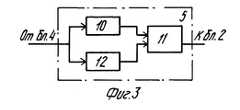
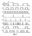
На фиг.1 приведена схема генератора псевдослучайных N-разрядных двоичных чисел; на фиг.2 и 3 функциональные схемы соответственно умножителя частоты и формирователя коротких импульсов; на фиг.4 временные диаграммы, поясняющие принцип работы генератора псевдослучайных N-разрядных двоичных чисел; на фиг.5 временные диаграммы, поясняющие принцип работы умножителя частоты. Figure 1 shows a diagram of a generator of pseudo-random N-bit binary numbers; Figures 2 and 3 are functional diagrams of a frequency multiplier and a short pulse shaper, respectively; figure 4 timing diagrams explaining the principle of operation of the generator of pseudo-random N-bit binary numbers; figure 5 timing diagrams explaining the principle of operation of the frequency multiplier.
Предлагаемое устройство содержит генератор периодических импульсов (ГПИ) 1, элемент ИЛИ 2, генератор опорной последовательности (ГОП) 3, умножители частоты (УЧ) 4.1-4.n, формирователи коротких импульсов (ФКИ) 5.1-5n, линии задержки (ЛЗ) 6.1-6.n, элементы И 7.1-7.n, блок памяти (БП) 8 и выходы генератора 9.1-9.n. The proposed device contains a periodic pulse generator (GUI) 1, an
Умножители частоты 4.1-4. n содержат элементы задержки 13.1 и 13.2, элементы И 14.1 и 14.2, элемент НЕ 15 и элемент ИЛИ 16. Frequency Multipliers 4.1-4. n contain delay elements 13.1 and 13.2, AND elements 14.1 and 14.2,
Формирователи коротких импульсов 5.1-5.n содержат элемент НЕ 10, элемент И 11 и линию задержки 12. Shapers of short pulses 5.1-5.n contain the
Генератор псевдослучайных N-разрядных двоичных чисел использует следующий принцип работы. The pseudo random N-bit binary number generator uses the following principle of operation.
Пусть дана последовательность псевдослучайных двоичных чисел g(t) с частотой следования F, из которой формируются n-опорных последовательностей псевдослучайных двоичных чисел с частотами следования
g1(t)20F, g3(t)21F, g3(t)22F, gn(t)2n-1F. (1)
Самый старший n-й разряд формируется с частотой 2n-1F, n-1-й разряд с частотой 2n-2F и т.д. а первый разряд (самый младший) с частотой 20F.Let a sequence of pseudo-random binary numbers g (t) be given with a repetition rate F, from which n-support sequences of pseudo-random binary numbers with repetition frequencies are formed
g1 (t) 20 F, g3 (t) 21 F, g3 (t) 22 F, gn (t) 2n-1 F. (1)
The oldest n-th digit is formed with a frequency of 2n-1 F, n-1-th digit with a frequency of 2n-2 F, etc. and the first digit (the youngest) with a frequency of 20 F.
В результате будет получено псевдослучайное N-разрядное число с равновероятным законом распределения. As a result, a pseudo-random N-bit number with an equally probable distribution law will be obtained.

Действительно, автокорреляционная функция псевдослучайного N-разрядного двоичного числа Rg(τ) будет удовлетворять требованию равновероятности, т.к. будет равняться взвешенной сумме автокорреляционных функций последовательностей случайных последовательностей gi(t)2i-1 с коэффициентами, равными квадрату веса соответствующему разряда числа
где i номер псевдослучайной последовательности, формирующей соответствующий разряд [1]
Откуда следует, что к самым старшим разрядам N-разрядного псевдослучайного двоичного числа необходимо предъявлять самые высокие требования "случайности", а к самым младшим существенно заниженные, без ущерба качества равномерного закона их распределения.
Indeed, the autocorrelation function of a pseudo-random N-bit binary number Rg (τ) will satisfy the requirement of equiprobability, since will be equal to the weighted sum of the autocorrelation functions of sequences of random sequences gi (t) 2i-1 with coefficients equal to the square of the weight corresponding to the discharge of the number
where i is the number of the pseudo-random sequence forming the corresponding bit [1]
Whence it follows that the highest requirements of “randomness” must be presented to the highest-order bits of an N-bit pseudo-random binary number, and the least significant ones to the least significant ones, without compromising on the quality of the uniform law of their distribution.
Предлагаемое устройство работает следующим образом. The proposed device operates as follows.
В начальный момент времени импульс с выхода ГПИ 1 (фиг.4a) скважности T/τ=2 (где T-период следования последовательности импульсов, τ длительность импульсов) поступает на вход УЧ 4.1 и ФКИ 5.1, где соответственно происходит умножение частоты следования импульсов вдвое (фиг.4b) и формируется короткий импульс по заднему фронту входного импульса (фиг.4d). С выхода УЧ 4.1 (фиг. 5b) последовательность импульсов поступает на вход УЧ 4.2 и ФКИ 5.2, где также происходит соответственно умножение частоты следования импульсов вдвое (фиг.5c) и формирование короткого импульса (фиг.5e). Сформированный короткий импульс через элемент ИЛИ 2 запускает ГОП 3, на выходе которого формируется одно из значений псевдослучайного числа g(t) ноль или единица, которое поступает на вторые входы элементов И 7.1-7.n. Разрешающий импульс с выхода ФКИ 5.1, пройдя через линию задержки 6.1, время задержки которой есть сумма времен задержек в элементе ИЛИ 2 и времени формирования одного разряда псевдослучайного числа в ГОП tз tили + tгоп в ГОП, записывает значение g(t) в первый разряд БП 8. Аналогично будут формироваться другие разряды с той лишь реакцией, что частота смены последующего значения разряда будет удваиваться.At the initial time, the pulse from the output of the GUI 1 (Fig. 4a) of the duty cycle T / τ = 2 (where T is the period of the sequence of pulses, τ is the pulse duration) is fed to the input of UCH 4.1 and FKI 5.1, where the pulse repetition rate is doubled, respectively (fig.4b) and a short pulse is formed along the trailing edge of the input pulse (fig.4d). From the output of the frequency converter 4.1 (Fig. 5b), the pulse train is fed to the input of the frequency converter 4.2 and the PCF 5.2, where the pulse repetition rate is also doubled respectively (Fig. 5c) and a short pulse is generated (Fig. 5e). Formed a short pulse through the element OR 2 starts GOP 3, the output of which is formed by one of the values of the pseudorandom number g (t) zero or one, which is fed to the second inputs of the elements AND 7.1-7.n. The resolving pulse from the output of the FCI 5.1, passing through the delay line 6.1, the delay time of which is the sum of the delay times in the
Умножитель частоты 4.1-4.n работает следующим образом. The frequency multiplier 4.1-4.n works as follows.
С выходе ГПИ 1 последовательность импульсов скважности T/t 2 (фиг.5a) поступает на элемент задержки 13.1, время задержки которой tлз1 t/2 (фиг. 5v), и элемент НЕ 15 (фиг.5z), где они соответственно задерживаются и инвертируются. В момент одновременного присутствия импульсов на входах элемента И 14.1 будет сформирован импульс. Кроме того, импульс будет сформирован и на выходе элемента И 14.2 в момент присутствия на первом входе инвертированного и задержанного импульса, поступающего с выхода элемента НЕ, на величину tлз2 t/2-tне (где tне время задержки на элементе НЕ 15), и входного импульса. Элемент ИЛИ 16 формирует удвоенную частоту следования импульсов (фиг.4b) из последовательностей импульсов, поступающих на его вход с выходов соответственно, элементов И 14.1 и 14.2 (фиг.5h,g). Если частота следования входной последовательности импульсов равна F=1/T при скважности равного 2, то выходная удвоенная частота следования импульсов есть сумма последовательностей удвоенной скважности с той же частотой следования импульсов, T/(0,5τ)+T/(0,5τ)=2(T/0,5τ) или F 1/2T, 2F=1/T.With the output of the GUI 1, the pulse sequence of the duty cycle T / t 2 (Fig. 5a) is supplied to the delay element 13.1, the delay time of which is tlz1 t / 2 (Fig. 5v), and the element is NOT 15 (Fig. 5z), where they are respectively delayed and are inverted. At the time of the simultaneous presence of pulses at the inputs of the element And 14.1 a pulse will be formed. In addition, a pulse will be generated at the output of the AND element 14.2 at the moment of the presence of an inverted and delayed pulse coming from the output of the element NOT at the first input by the value tlz2 t / 2-tnot (where t isnot the delay time on the element NOT 15) , and input pulse. The
Формирователь коротких импульсов 5.1-5.n работает следующим образом. Shaper pulses 5.1-5.n works as follows.
На входы элемента НЕ 10 и линии задержки 12 поступает опорная последовательность импульсов (фиг.4a), которая в этих элементах соответственно инвертируется и задерживается. Тогда в момент присутствия на входах элемента И 11 этих импульсов сформируется короткий импульс, длительность которого будет определяться временем задержки элемента НЕ 12 tлз и достаточного для его формирования в элементе И 11 и запуска ГОП 3.The inputs of the
По сравнению с прототипом генератор псевдослучайных N-разрядных двоичных чисел значительно проще и генерирует требуемые последовательности весьма экономичным способом, используя единственный задающий генератор псевдослучайных чисел. При этом с выхода устройства снимается псевдослучайное N-разрядное двоичное число при каждом такте его работы, при сохранении жестких требований к выходной последовательности. Тогда как в известном устройстве требуется n-опорных генераторов, что весьма не экономично и проблематично, т.к. при увеличении значности псевдослучайных N-разрядных двоичных чисел необходимо иметь абсолютно одинаковых характеристики у каждого генератора опорной последовательности [1]
При формировании псевдослучайных N-разрядных двоичных чисел последовательным способом достичь большой скорости весьма затруднительно, так как в (n-1)-раз должна увеличиться частота генерации опорной последовательности на выходе устройства, что в свою очередь влияет на качество опорной последовательности при таких частотах генерации [2]
Источники информации:
1. Яковлев В.В. Стохастические вычислительные машины. Л. Машиностроение, 1974. с. 191.Compared to the prototype, the pseudo-random N-bit binary number generator is much simpler and generates the required sequences in a very economical way using a single pseudo random number generator. At the same time, a pseudo-random N-bit binary number is removed from the output of the device at each step of its operation, while maintaining strict requirements for the output sequence. While the known device requires n-reference generators, which is not very economical and problematic, because when increasing the value of pseudorandom N-bit binary numbers, it is necessary to have exactly the same characteristics for each generator of the reference sequence [1]
When generating pseudo-random N-bit binary numbers in a sequential way, it is very difficult to achieve high speed, since the frequency of generating the reference sequence at the output of the device should increase (n-1) times, which in turn affects the quality of the reference sequence at such generation frequencies [ 2]
Information sources:
1. Yakovlev V.V. Stochastic computers. L. Mechanical Engineering, 1974. p. 191.
2. Бобнев М. П. Генерирование случайных сигналов.-М. Энергия, 1971, с. 170. 2. Bobnev M. P. Generation of random signals.-M. Energy, 1971, p. 170.
Claims (3)
Translated fromRussianPriority Applications (1)
| Application Number | Priority Date | Filing Date | Title |
|---|---|---|---|
| RU94013153ARU2080651C1 (en) | 1994-04-14 | 1994-04-14 | Generator of random n-bit binary numbers |
Applications Claiming Priority (1)
| Application Number | Priority Date | Filing Date | Title |
|---|---|---|---|
| RU94013153ARU2080651C1 (en) | 1994-04-14 | 1994-04-14 | Generator of random n-bit binary numbers |
Publications (2)
| Publication Number | Publication Date |
|---|---|
| RU94013153A RU94013153A (en) | 1996-02-27 |
| RU2080651C1true RU2080651C1 (en) | 1997-05-27 |
Family
ID=20154722
Family Applications (1)
| Application Number | Title | Priority Date | Filing Date |
|---|---|---|---|
| RU94013153ARU2080651C1 (en) | 1994-04-14 | 1994-04-14 | Generator of random n-bit binary numbers |
Country Status (1)
| Country | Link |
|---|---|
| RU (1) | RU2080651C1 (en) |
Cited By (4)
| Publication number | Priority date | Publication date | Assignee | Title |
|---|---|---|---|---|
| RU2168260C1 (en)* | 2000-05-25 | 2001-05-27 | Воронежский государственный технический университет | Random signal generator |
| RU2211481C2 (en)* | 2001-10-08 | 2003-08-27 | Военный университет связи | Random-number generator |
| RU173172U1 (en)* | 2016-02-01 | 2017-08-15 | Открытое Акционерное Общество "Пеленг" | NON-LINEAR FEEDBACK Pseudorandom Generator |
| RU2690765C1 (en)* | 2018-07-27 | 2019-06-05 | Акционерное общество "Современные беспроводные технологии" | Periodic pseudorandom binary sequence generator of complex structure |
- 1994
- 1994-04-14RURU94013153Apatent/RU2080651C1/enactive
Non-Patent Citations (1)
| Title |
|---|
| Яковлев В.В. Стохастические вычислительные машины. - Л.: Машиностроение, 1974, с. 191. Бобнев М.П. Генерирование случайных сигналов. - М.: Энергия, 1971, с. 170. Четвериков В. Н. и др. Стохастические вычислительные устройства систем моделирования. - М.: Машиностроение, 1969, с. 94.* |
Cited By (4)
| Publication number | Priority date | Publication date | Assignee | Title |
|---|---|---|---|---|
| RU2168260C1 (en)* | 2000-05-25 | 2001-05-27 | Воронежский государственный технический университет | Random signal generator |
| RU2211481C2 (en)* | 2001-10-08 | 2003-08-27 | Военный университет связи | Random-number generator |
| RU173172U1 (en)* | 2016-02-01 | 2017-08-15 | Открытое Акционерное Общество "Пеленг" | NON-LINEAR FEEDBACK Pseudorandom Generator |
| RU2690765C1 (en)* | 2018-07-27 | 2019-06-05 | Акционерное общество "Современные беспроводные технологии" | Periodic pseudorandom binary sequence generator of complex structure |
Similar Documents
| Publication | Publication Date | Title |
|---|---|---|
| US6046616A (en) | Two dimensional random pulse generator | |
| RU2080651C1 (en) | Generator of random n-bit binary numbers | |
| RU2163027C2 (en) | Pseudorandom sequence generator (alternatives) | |
| RU2081450C1 (en) | Generator of n-bit random sequence | |
| KR100228592B1 (en) | Cycle generator circuit of semiconductor test equipment | |
| RU2120179C1 (en) | White noise generator ( variants ) | |
| US5761100A (en) | Period generator for semiconductor testing apparatus | |
| RU2013802C1 (en) | Generator of pseudorandom sequences of binary numbers | |
| RU2092892C1 (en) | Uniform distribution random number generator | |
| RU2081451C1 (en) | Generator of random number sequence | |
| SU943720A1 (en) | Pseudo-random pulse train generator | |
| RU2553057C1 (en) | Device to generate systems of double derivative non-linear recurrent sequences | |
| SU871314A2 (en) | Discrete matched filter | |
| SU796834A1 (en) | Pseudorandom pulse train generator | |
| KR940004340A (en) | Pulse radar system signal generator | |
| SU932602A1 (en) | Random pulse train generator | |
| SU1223350A1 (en) | Pseudorandom number generator | |
| SU1064437A2 (en) | Pseudorandom pulse sequence generator | |
| SU1462469A1 (en) | Generator of random-duration pulses | |
| SU1023326A1 (en) | Orthogonal pseudorandom sequence generator | |
| SU1672445A1 (en) | Equally distributed random numbers generator | |
| SU1670776A1 (en) | Generator of random voltages | |
| SU1504803A1 (en) | N-ary code shaper | |
| SU1644385A1 (en) | Device for generating quaternary-coded sequences | |
| SU1140234A2 (en) | Pulse sequence generator |