RU2077358C1 - Sound signalling apparatus for toy - Google Patents
Sound signalling apparatus for toyDownload PDFInfo
- Publication number
- RU2077358C1 RU2077358C1RU93052124ARU93052124ARU2077358C1RU 2077358 C1RU2077358 C1RU 2077358C1RU 93052124 ARU93052124 ARU 93052124ARU 93052124 ARU93052124 ARU 93052124ARU 2077358 C1RU2077358 C1RU 2077358C1
- Authority
- RU
- Russia
- Prior art keywords
- output
- input
- sound
- inverter
- toy
- Prior art date
Links
- 230000011664signalingEffects0.000titleabstractdescription3
- 230000033001locomotionEffects0.000claimsabstractdescription18
- 230000005236sound signalEffects0.000claimsabstractdescription13
- 239000003990capacitorSubstances0.000claimsdescription15
- 238000009434installationMethods0.000claimsdescription11
- 239000011810insulating materialSubstances0.000claims1
- 230000000694effectsEffects0.000abstract2
- 238000010276constructionMethods0.000abstract1
- 239000000126substanceSubstances0.000abstract1
- 230000001133accelerationEffects0.000description6
- 230000015572biosynthetic processEffects0.000description3
- 230000002411adverseEffects0.000description1
- 230000000903blocking effectEffects0.000description1
- 238000006243chemical reactionMethods0.000description1
- 238000004891communicationMethods0.000description1
- 230000008878couplingEffects0.000description1
- 238000010168coupling processMethods0.000description1
- 238000005859coupling reactionMethods0.000description1
- 238000010586diagramMethods0.000description1
- 238000004519manufacturing processMethods0.000description1
- 230000000737periodic effectEffects0.000description1
- 230000005855radiationEffects0.000description1
- 230000000630rising effectEffects0.000description1
- 238000005507sprayingMethods0.000description1
- 230000003068static effectEffects0.000description1
- 238000003786synthesis reactionMethods0.000description1
Images


Landscapes
- Toys (AREA)
Abstract
Description
Translated fromRussianИзобретение относится к электронным игрушкам и может быть использовано в движущихся самоходных или механических игрушках с изменением скорости и/или направления движения с формированием звукового прерывистого сигнала. The invention relates to electronic toys and can be used in moving self-propelled or mechanical toys with a change in speed and / or direction of movement with the formation of an intermittent sound signal.
Известно устройство звуковой сигнализации для игрушки, содержащее бесконтактный датчик, реагирующий на приближение какого-либо объекта и содержащий два детектора, фиксирующие приближение объекта и подающие сигнал на схему памяти, которая управляет схемой генерирования звуковых сигналов, содержащей блок управления, запоминающее устройство с набором данных звуковых сигналов, блок генерирования звука и цифроаналоговый преобразователь. Блок управления включается при поступлении установочного сигнала со схемы памяти, считывает с запоминающего устройства данные звукового сигнала в определенной последовательности и подает их в блок генерирования звука, выходной сигнал которого преобразуется цифроаналоговым преобразователем в звуковые сигналы звукоизлучателя. По окончании синтезирования звука блок управления сбрасывает схему памяти 1. A sound device for a toy is known that contains a proximity sensor that responds to the proximity of an object and contains two detectors that detect the proximity of the object and provide a signal to a memory circuit that controls the sound signal generation circuit containing a control unit, a storage device with a set of sound data signals, sound generation unit and digital-to-analog converter. The control unit is turned on when the installation signal is received from the memory circuit, reads the sound signal data from the storage device in a certain sequence and feeds it to the sound generating unit, the output signal of which is converted by the digital-to-analog converter into sound signals of the sound emitter. At the end of the sound synthesis, the control unit resets the
Недостатками известного устройства являются:
сложная схема формирования звуковых сигналов, содержащая значительное число блоков, в том числе блок памяти, в который в процессе изготовления заносится информация;
наличие излучателя высокой частоты в бесконтактном датчике и приемника отраженных сигналов высокой частоты, усложняющих схему и требующих преобразования постоянного напряжения питания в радиосигнал высокой частоты, что связано с затратой энергии;
наличие высокочастотного излучения, которое даже в пределах санитарных норм отрицательно сказывается на организме играющего ребенка, что недопустимо даже в незначительных размерах.The disadvantages of the known device are:
a complex scheme for generating sound signals containing a significant number of blocks, including a memory block, into which information is entered during the manufacturing process;
the presence of a high-frequency emitter in a proximity sensor and a receiver of reflected high-frequency signals that complicate the circuit and require the conversion of a constant voltage to a high-frequency radio signal, which is associated with the expenditure of energy;
the presence of high-frequency radiation, which even within sanitary standards adversely affects the body of the playing child, which is unacceptable even in small amounts.
Предлагаемое изобретение решает задачу повышения игровой занимательности при одновременном упрощении устройства и снижении энергопотребления. The present invention solves the problem of increasing gaming entertainment while simplifying the device and reducing power consumption.
Сущность изобретения поясняется чертежами, где на фиг. 1 приведена функциональная схема устройства, на фиг. 2 пример выполнения датчика движения и положения 2, на фиг. 3 пример выполнения дискриминатора 3, на фиг. 4 показан пример выполнения блока начальной установки 4 и одновибратора 5, на фиг. 5 изображен пример выполнения генератора звуковых сигналов 6. The invention is illustrated by drawings, where in FIG. 1 shows a functional diagram of the device, in FIG. 2 an example of the motion sensor and
Устройство содержит (см. фиг. 1) блок питания 1, датчик 2 движения и положения игрушек, дискриминатор 3, блок 4 начальной установки, одновибратор 5, узел 6 генерирования звуковых сигналов 6, состоящий из генератора 7 стробирующих сигналов и генератора 8 звуковой частоты, звуковой излучатель 9. The device contains (see Fig. 1) a
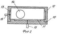
Датчик 2 движения и положения (см. фиг. 2) содержит корпус 10, электропроводящий слой 11, крышку 12, электропроводящий слой 13 крышки, шарик 14, контакты 15, 16. The motion and position sensor 2 (see FIG. 2) comprises a
Дискриминатор 3 (см. фиг. 3) содержит резисторы 17, 18 и дифференцирующий конденсатор 19. The discriminator 3 (see Fig. 3) contains
Блок начальной установки 4 (см. фиг. 4) содержит диод 20 и резистор 21 гальванической связи. The initial installation unit 4 (see Fig. 4) contains a
Одновибратор 5 (см. фиг. 4) содержит резистор 22, инверторы 23, 24, диод 25 и конденсатор 26. The one-shot 5 (see Fig. 4) contains a
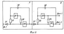
Генератор 7 стробирующих сигналов (см. фиг. 5) содержит резисторы 27, 28, инверторы 29, 30, диод 31, конденсатор 32. The
Генератор 8 звуковой частоты (см. фиг. 5) содержит резисторы 33, 34, инверторы 35, 36, диод 37, конденсатор 38. The sound frequency generator 8 (see Fig. 5) contains
Блок питания 1 последовательно соединен с датчиком 2 движения и положения и дискриминатором 3 и подключен к блоку 4 начальной установки, а также предназначен для питания элементов электронной схемы всего устройства. The
Датчик 2 движения и положения предназначен для определения состояния игрушки и наличия ее движения с ускорением или без ускорения в горизонтальной плоскости. The motion and
В частном случае выполнения датчик движения и положения (см. фиг. 2) состоит из корпуса 10, на дне которого нанесен напылением или наклеен токопроводящий слой 13. На дне корпуса 10 свободно размещен токопроводящий шарик 14, который при касании токопроводящего слоя 13 замыкает с ним токопроводящий слой 11. Токопроводящие слои 11 и 13, соединены соответственно с контактами 15 и 16, которые соединяются между собой в том случае, когда шарик 14, находясь на токопроводящем слое 11 касается слоя 13, и размыкаются, когда шарик 14 не касается слоя 13. In the particular case of execution, the motion and position sensor (see Fig. 2) consists of a
Таким образом на выходе датчика 2 формируется сигнал "обрыв" (разомкнутое состояние контактов 15 и 16 датчика) "корпус" (замкнутое состояние контактов датчика). Thus, at the output of the
При изменении скорости, т.е. при появлении ускорения шарик 14 изменяет свое положение, касается слоя 13 и кратковременно замыкает слои 11 и 13 между собой, на выходе датчика 2 появляется импульс, поступающий на второй вход дискриминатора 3, на первый вход которого подается напряжение питания от блока питания 1. When changing speed, i.e. when acceleration appears, the
В частном случае выполнения датчика 2 движения и положения дно корпуса 10 выполнено вогнутым. Шарик 14 без движения и при равномерном движении находится в нижней части вогнутого дна и может замкнуть слой 11 со слоем 13 только при определенном ускорении, величина которого зависит от веса шарика и радиуса кривизны вогнутого дна. In the particular case of the implementation of the
Таким образом выбором этих параметров может быть получен датчик, реагирующий на определенное ускорение. Thus, by choosing these parameters, a sensor can be obtained that responds to a specific acceleration.
Дискриминатор 3 предназначен для преобразования кратковременного замыкания контактов датчика 2 в короткий отрицательный импульс напряжения на первом входе одновибратора 5, с которым соединен выход дискриминатора 3. The discriminator 3 is designed to convert the short-circuit of the contacts of the
Дискриминатор 3 может быть выполнен, например, по схеме фиг. 3 и состоит из резисторов и дифференцирующего конденсатора. The discriminator 3 can be performed, for example, according to the scheme of FIG. 3 and consists of resistors and a differentiating capacitor.
Блок начальной установки 4 предназначен для установки в начальное (нулевое) состояние одновибратора 5 и обеспечения гальванической связи одновибратора 5 с блоком 1 питания. The
Блок 4 начальной установки соединен со вторым входом одновибратора 5, может быть выполнен, например, по схеме фиг. 4. Он содержит диод 20 для быстрого разряда конденсатора 26 при установке одновибратора 5 в начальное состояние и резистор 21 для сохранения гальванической связи положительной обкладки конденсатора 26 с блоком питания 1 при обратном смещении диода 25. The
Одновибратор 5 соединен со входом узла 6 генерирования звуковых сигналов и предназначен для нормирования импульсов с датчика 2, имеющих произвольную длительность. Таким образом, при кратковременном замыкании контактов датчика 2 обеспечивается звуковая сигнализация определенной длительности, определяемой выходным импульсом одновибратора 5. The one-
Одновибратор 5 может быть выполнен, например, по схеме фиг. 4 и содержит входной резистор 22, инверторы 23, 24, диод 25, конденсатор 26. The one-
При разомкнутых контактах датчика 2 вход одновибратора 5 подключен через дискриминатор 3 к блоку питания 1, диод 25 закрыт, т.к. его катод через резистор 21 блока 4 подключен также к блоку питания 1. На выходе инвертора 23 нулевой потенциал, а на выходе инвертора 24 положительный потенциал. Конденсатор 26 не заряжен. When the contacts of the
При появлении на входе одновибратор 5 отрицательного импульса (при кратковременном замыкании контактов датчика 2) диод 25 остается закрытым, на выходе инвертора 23 появляется положительный импульс, а на выходе инвертора 24 отрицательный импульс, диод 25 открывается и конденсатор 26 начинает заряжаться через резистор 21, диод 25 и параллельно через резистор 21 блока начальной установки 4, при этом потенциал на входе инвертора 23 близок к нулевому (отличается от нулевого на величину падения на напряжения на прямосмещенном р-n-переходе диода 25) и поддерживает нулевой потенциал на выходе инвертора 24. Это состояние сохраняется до того, как конденсатор 26 зарядится до напряжения, при котором потенциал на входе инвертора 23 будет восприниматься как положительный, тогда на его выходе образуется нулевой потенциал, а на выходе инвертора 26 положительный. Одновибратор 5 вернется в исходное состояние, при этом конденсатор 26 без задержки разрядится через диод 20 блока 4, и одновибратор может формировать следующий импульс при наличии сигнала от датчика 2. When a negative impulse appears at the input of the one-shot 5 (when the contacts of the
Узел 6 предназначен для формирования в пределах длительности импульса одновибратора 5 прерывистых звуковых сигналов и соединен со звуковым излучателем 9. The node 6 is intended for the formation within the pulse duration of the one-
Узел 6 состоит из последовательно соединенных генератора стробирующих сигналов 7, формирующего прямоугольные импульсы низкой частоты, стробирующие работу генератора звуковой частоты 8. The node 6 consists of a series-connected generator of the
Генератор 7 может быть выполнен, например, по схеме фиг. 5 и представляет собой генератор прямоугольных импульсов, при единичном уровне сигнала на выходе блокирующий работу генератора звуковой частоты 8. Таким образом, выходной сигнал генератора 8 представляет собой пачки импульсов звуковой частоты. The
Генератор 8 может быть выполнен, например, по схеме фиг. 5. The
Звуковой излучатель 9 может быть выполнен на основе пьезоэлектрического сигнализатора звука. The sound emitter 9 can be made on the basis of a piezoelectric sound signaling device.
Устройство работает следующим образом. The device operates as follows.
При неподвижном состоянии игрушки датчик движения и положения 2 формирует статический сигнал обрыва цепи "блок питания 1 дискриминатор 3+ или короткого замыкания этой цепи, и на выходе дискриминатора 3 формируется и положительный потенциал, при котором одновибратор остается в исходном (нулевом) состоянии. Узел 6 генерирования звуковых сигналов не формирует импульсы звуковой частоты. When the toy is stationary, the motion and
Устройство работает аналогично при равномерном движении без ускорения, при котором датчик 2 не формирует сигнал разрыва цепи. The device operates similarly with uniform movement without acceleration, in which the
При появлении ускорения (движение игрушки с места, изменение направления движения и т. п.) сигнал на выходе датчика 2 изменяется из состояния обрыв цепи в состояние короткое замыкание за счет кратковременного замыкания контактов датчика 2. When acceleration appears (movement of the toy from its place, change of direction, etc.), the signal at the output of
Дискриминатор 3 формирует короткий отрицательный импульс, запускается одновибратор 5, на его выходе формируется сигнал заданной длительности, который по переднему фронту запускает генератор стробирующих сигналов 7. На его выходе формируются периодические прямоугольные импульсы в пределах действия выходного импульса одновибратора 5. Выходной положительный импульс генератора 7 блокирует работу генератора низкой частоты 8, в промежутках между импульсами генератора 7 генератор 8 запускается и формирует импульсы звуковой частоты, поступающие на звукоизлучатель 9, который таким образом издает прерывистые сигналы звуковой частоты с нормированной длительностью звучания. The discriminator 3 generates a short negative impulse, a one-
Использование изобретения повышает игровую занимательность устройства. The use of the invention increases the gaming entertainment of the device.
Claims (1)
Translated fromRussianPriority Applications (1)
| Application Number | Priority Date | Filing Date | Title |
|---|---|---|---|
| RU93052124ARU2077358C1 (en) | 1993-11-18 | 1993-11-18 | Sound signalling apparatus for toy |
Applications Claiming Priority (1)
| Application Number | Priority Date | Filing Date | Title |
|---|---|---|---|
| RU93052124ARU2077358C1 (en) | 1993-11-18 | 1993-11-18 | Sound signalling apparatus for toy |
Publications (2)
| Publication Number | Publication Date |
|---|---|
| RU93052124A RU93052124A (en) | 1997-03-20 |
| RU2077358C1true RU2077358C1 (en) | 1997-04-20 |
Family
ID=20149319
Family Applications (1)
| Application Number | Title | Priority Date | Filing Date |
|---|---|---|---|
| RU93052124ARU2077358C1 (en) | 1993-11-18 | 1993-11-18 | Sound signalling apparatus for toy |
Country Status (1)
| Country | Link |
|---|---|
| RU (1) | RU2077358C1 (en) |
Cited By (9)
| Publication number | Priority date | Publication date | Assignee | Title |
|---|---|---|---|---|
| US8089458B2 (en) | 2000-02-22 | 2012-01-03 | Creative Kingdoms, Llc | Toy devices and methods for providing an interactive play experience |
| US8226493B2 (en) | 2002-08-01 | 2012-07-24 | Creative Kingdoms, Llc | Interactive play devices for water play attractions |
| US8475275B2 (en) | 2000-02-22 | 2013-07-02 | Creative Kingdoms, Llc | Interactive toys and games connecting physical and virtual play environments |
| US8608535B2 (en) | 2002-04-05 | 2013-12-17 | Mq Gaming, Llc | Systems and methods for providing an interactive game |
| US8702515B2 (en) | 2002-04-05 | 2014-04-22 | Mq Gaming, Llc | Multi-platform gaming system using RFID-tagged toys |
| US8708821B2 (en) | 2000-02-22 | 2014-04-29 | Creative Kingdoms, Llc | Systems and methods for providing interactive game play |
| US8753165B2 (en) | 2000-10-20 | 2014-06-17 | Mq Gaming, Llc | Wireless toy systems and methods for interactive entertainment |
| US8758136B2 (en) | 1999-02-26 | 2014-06-24 | Mq Gaming, Llc | Multi-platform gaming systems and methods |
| US9446319B2 (en) | 2003-03-25 | 2016-09-20 | Mq Gaming, Llc | Interactive gaming toy |
- 1993
- 1993-11-18RURU93052124Apatent/RU2077358C1/enactive
Non-Patent Citations (1)
| Title |
|---|
| Заявка N 3-9754, кл. A 63H 3/33, 1991.* |
Cited By (64)
| Publication number | Priority date | Publication date | Assignee | Title |
|---|---|---|---|---|
| US9861887B1 (en) | 1999-02-26 | 2018-01-09 | Mq Gaming, Llc | Multi-platform gaming systems and methods |
| US9186585B2 (en) | 1999-02-26 | 2015-11-17 | Mq Gaming, Llc | Multi-platform gaming systems and methods |
| US9468854B2 (en) | 1999-02-26 | 2016-10-18 | Mq Gaming, Llc | Multi-platform gaming systems and methods |
| US8888576B2 (en) | 1999-02-26 | 2014-11-18 | Mq Gaming, Llc | Multi-media interactive play system |
| US8758136B2 (en) | 1999-02-26 | 2014-06-24 | Mq Gaming, Llc | Multi-platform gaming systems and methods |
| US10300374B2 (en) | 1999-02-26 | 2019-05-28 | Mq Gaming, Llc | Multi-platform gaming systems and methods |
| US9731194B2 (en) | 1999-02-26 | 2017-08-15 | Mq Gaming, Llc | Multi-platform gaming systems and methods |
| US8686579B2 (en) | 2000-02-22 | 2014-04-01 | Creative Kingdoms, Llc | Dual-range wireless controller |
| US9713766B2 (en) | 2000-02-22 | 2017-07-25 | Mq Gaming, Llc | Dual-range wireless interactive entertainment device |
| US8475275B2 (en) | 2000-02-22 | 2013-07-02 | Creative Kingdoms, Llc | Interactive toys and games connecting physical and virtual play environments |
| US8491389B2 (en) | 2000-02-22 | 2013-07-23 | Creative Kingdoms, Llc. | Motion-sensitive input device and interactive gaming system |
| US10188953B2 (en) | 2000-02-22 | 2019-01-29 | Mq Gaming, Llc | Dual-range wireless interactive entertainment device |
| US9149717B2 (en) | 2000-02-22 | 2015-10-06 | Mq Gaming, Llc | Dual-range wireless interactive entertainment device |
| US9814973B2 (en) | 2000-02-22 | 2017-11-14 | Mq Gaming, Llc | Interactive entertainment system |
| US8708821B2 (en) | 2000-02-22 | 2014-04-29 | Creative Kingdoms, Llc | Systems and methods for providing interactive game play |
| US8368648B2 (en) | 2000-02-22 | 2013-02-05 | Creative Kingdoms, Llc | Portable interactive toy with radio frequency tracking device |
| US8089458B2 (en) | 2000-02-22 | 2012-01-03 | Creative Kingdoms, Llc | Toy devices and methods for providing an interactive play experience |
| US10307671B2 (en) | 2000-02-22 | 2019-06-04 | Mq Gaming, Llc | Interactive entertainment system |
| US8790180B2 (en) | 2000-02-22 | 2014-07-29 | Creative Kingdoms, Llc | Interactive game and associated wireless toy |
| US8814688B2 (en) | 2000-02-22 | 2014-08-26 | Creative Kingdoms, Llc | Customizable toy for playing a wireless interactive game having both physical and virtual elements |
| US9579568B2 (en) | 2000-02-22 | 2017-02-28 | Mq Gaming, Llc | Dual-range wireless interactive entertainment device |
| US8184097B1 (en) | 2000-02-22 | 2012-05-22 | Creative Kingdoms, Llc | Interactive gaming system and method using motion-sensitive input device |
| US9474962B2 (en) | 2000-02-22 | 2016-10-25 | Mq Gaming, Llc | Interactive entertainment system |
| US8169406B2 (en) | 2000-02-22 | 2012-05-01 | Creative Kingdoms, Llc | Motion-sensitive wand controller for a game |
| US8164567B1 (en) | 2000-02-22 | 2012-04-24 | Creative Kingdoms, Llc | Motion-sensitive game controller with optional display screen |
| US9931578B2 (en) | 2000-10-20 | 2018-04-03 | Mq Gaming, Llc | Toy incorporating RFID tag |
| US10307683B2 (en) | 2000-10-20 | 2019-06-04 | Mq Gaming, Llc | Toy incorporating RFID tag |
| US9480929B2 (en) | 2000-10-20 | 2016-11-01 | Mq Gaming, Llc | Toy incorporating RFID tag |
| US8961260B2 (en) | 2000-10-20 | 2015-02-24 | Mq Gaming, Llc | Toy incorporating RFID tracking device |
| US8753165B2 (en) | 2000-10-20 | 2014-06-17 | Mq Gaming, Llc | Wireless toy systems and methods for interactive entertainment |
| US9320976B2 (en) | 2000-10-20 | 2016-04-26 | Mq Gaming, Llc | Wireless toy systems and methods for interactive entertainment |
| US8248367B1 (en) | 2001-02-22 | 2012-08-21 | Creative Kingdoms, Llc | Wireless gaming system combining both physical and virtual play elements |
| US10179283B2 (en) | 2001-02-22 | 2019-01-15 | Mq Gaming, Llc | Wireless entertainment device, system, and method |
| US10758818B2 (en) | 2001-02-22 | 2020-09-01 | Mq Gaming, Llc | Wireless entertainment device, system, and method |
| US8384668B2 (en) | 2001-02-22 | 2013-02-26 | Creative Kingdoms, Llc | Portable gaming device and gaming system combining both physical and virtual play elements |
| US9393491B2 (en) | 2001-02-22 | 2016-07-19 | Mq Gaming, Llc | Wireless entertainment device, system, and method |
| US8913011B2 (en) | 2001-02-22 | 2014-12-16 | Creative Kingdoms, Llc | Wireless entertainment device, system, and method |
| US9162148B2 (en) | 2001-02-22 | 2015-10-20 | Mq Gaming, Llc | Wireless entertainment device, system, and method |
| US9737797B2 (en) | 2001-02-22 | 2017-08-22 | Mq Gaming, Llc | Wireless entertainment device, system, and method |
| US8711094B2 (en) | 2001-02-22 | 2014-04-29 | Creative Kingdoms, Llc | Portable gaming device and gaming system combining both physical and virtual play elements |
| US11278796B2 (en) | 2002-04-05 | 2022-03-22 | Mq Gaming, Llc | Methods and systems for providing personalized interactive entertainment |
| US10478719B2 (en) | 2002-04-05 | 2019-11-19 | Mq Gaming, Llc | Methods and systems for providing personalized interactive entertainment |
| US9616334B2 (en) | 2002-04-05 | 2017-04-11 | Mq Gaming, Llc | Multi-platform gaming system using RFID-tagged toys |
| US8827810B2 (en) | 2002-04-05 | 2014-09-09 | Mq Gaming, Llc | Methods for providing interactive entertainment |
| US10507387B2 (en) | 2002-04-05 | 2019-12-17 | Mq Gaming, Llc | System and method for playing an interactive game |
| US8702515B2 (en) | 2002-04-05 | 2014-04-22 | Mq Gaming, Llc | Multi-platform gaming system using RFID-tagged toys |
| US8608535B2 (en) | 2002-04-05 | 2013-12-17 | Mq Gaming, Llc | Systems and methods for providing an interactive game |
| US9463380B2 (en) | 2002-04-05 | 2016-10-11 | Mq Gaming, Llc | System and method for playing an interactive game |
| US9272206B2 (en) | 2002-04-05 | 2016-03-01 | Mq Gaming, Llc | System and method for playing an interactive game |
| US10010790B2 (en) | 2002-04-05 | 2018-07-03 | Mq Gaming, Llc | System and method for playing an interactive game |
| US8226493B2 (en) | 2002-08-01 | 2012-07-24 | Creative Kingdoms, Llc | Interactive play devices for water play attractions |
| US8961312B2 (en) | 2003-03-25 | 2015-02-24 | Creative Kingdoms, Llc | Motion-sensitive controller and associated gaming applications |
| US10022624B2 (en) | 2003-03-25 | 2018-07-17 | Mq Gaming, Llc | Wireless interactive game having both physical and virtual elements |
| US8373659B2 (en) | 2003-03-25 | 2013-02-12 | Creative Kingdoms, Llc | Wirelessly-powered toy for gaming |
| US9993724B2 (en) | 2003-03-25 | 2018-06-12 | Mq Gaming, Llc | Interactive gaming toy |
| US9770652B2 (en) | 2003-03-25 | 2017-09-26 | Mq Gaming, Llc | Wireless interactive game having both physical and virtual elements |
| US9707478B2 (en) | 2003-03-25 | 2017-07-18 | Mq Gaming, Llc | Motion-sensitive controller and associated gaming applications |
| US10369463B2 (en) | 2003-03-25 | 2019-08-06 | Mq Gaming, Llc | Wireless interactive game having both physical and virtual elements |
| US9039533B2 (en) | 2003-03-25 | 2015-05-26 | Creative Kingdoms, Llc | Wireless interactive game having both physical and virtual elements |
| US10583357B2 (en) | 2003-03-25 | 2020-03-10 | Mq Gaming, Llc | Interactive gaming toy |
| US9446319B2 (en) | 2003-03-25 | 2016-09-20 | Mq Gaming, Llc | Interactive gaming toy |
| US11052309B2 (en) | 2003-03-25 | 2021-07-06 | Mq Gaming, Llc | Wireless interactive game having both physical and virtual elements |
| US9393500B2 (en) | 2003-03-25 | 2016-07-19 | Mq Gaming, Llc | Wireless interactive game having both physical and virtual elements |
| US9675878B2 (en) | 2004-09-29 | 2017-06-13 | Mq Gaming, Llc | System and method for playing a virtual game by sensing physical movements |
Similar Documents
| Publication | Publication Date | Title |
|---|---|---|
| RU2077358C1 (en) | Sound signalling apparatus for toy | |
| US4659919A (en) | Optical sensing circuit for audio activation of toys | |
| US4195284A (en) | Sound generator | |
| US3594768A (en) | Motion detecting apparatus and intruder alarm | |
| US3912952A (en) | Piezoelectric acoustic multiple tone generator | |
| US4294035A (en) | Device with visual and audio output | |
| IE38424L (en) | Convertion of light energy to electrically energy | |
| US3586919A (en) | Remote control device | |
| JPS6318080Y2 (en) | ||
| JPS58193475A (en) | Ultrasonic reflection type detector | |
| JP3093140B2 (en) | Astable multivibrator | |
| JPS6027435Y2 (en) | chime sound generator | |
| JP2998012B2 (en) | Pest repelling device | |
| JPS56113171A (en) | Toner detection device | |
| JPS6111833Y2 (en) | ||
| GB1604881A (en) | Toys | |
| JPS56116323A (en) | Acl signal generating circuit in integrated circuit | |
| JPS56169926A (en) | Automatic channel selecting device | |
| SU1053829A1 (en) | Ultrasonic locator for the blind | |
| JPS5846584Y2 (en) | timed circuit | |
| RU1798895C (en) | Multivibrator | |
| KR0163886B1 (en) | Initially discharging control circuit to compensate memory effect of nicd battery | |
| JPS5539057A (en) | Moving body detector using ultrasonic wave | |
| SU1582007A1 (en) | Ultrasonic device for measuring thickness of articles | |
| WO1991017634A1 (en) | Transmitter/receiver system for locating misplaced objects |