RU2070682C1 - Search light type headlight for self-propelled vehicles - Google Patents
Search light type headlight for self-propelled vehiclesDownload PDFInfo
- Publication number
- RU2070682C1 RU2070682C1RU92004341ARU92004341ARU2070682C1RU 2070682 C1RU2070682 C1RU 2070682C1RU 92004341 ARU92004341 ARU 92004341ARU 92004341 ARU92004341 ARU 92004341ARU 2070682 C1RU2070682 C1RU 2070682C1
- Authority
- RU
- Russia
- Prior art keywords
- lens
- reflective
- segment
- reflective surface
- light
- Prior art date
Links
- 230000000694effectsEffects0.000abstractdescription2
- 239000000126substanceSubstances0.000abstract1
- 238000005286illuminationMethods0.000description4
- 230000004313glareEffects0.000description3
- 230000002411adverseEffects0.000description1
- 230000035515penetrationEffects0.000description1
- 230000008447perceptionEffects0.000description1
Images


Landscapes
- Non-Portable Lighting Devices Or Systems Thereof (AREA)
Abstract
Description
Translated fromRussianИзобретение относится к фаре проекционного типа, предназначенной для самоходных транспортных средств, при этом фара обладает повышенной интенсивностью освещения проходящим световым лучом над границей света и темноты и повышенным проникновением света в туман. The invention relates to a projection-type headlamp intended for self-propelled vehicles, the headlamp having a high intensity of illumination by a transmitted light beam above the border of light and darkness and increased penetration of light into the fog.
В случае хорошо известных эллиптических диоптрических фар, содержащих эллиптический отражатель, экран и линзу, линза конструируется для отвода светового луча от отражателя таким образом, что он почти полностью направляется ниже горизонтальной плоскости, так что интенсивность освещения над упомянутой плоскостью минимальна. Это позволяет уменьшить ослепление водителей проходящих автомобилей, но, с другой стороны, вследствие слабого освещения восприятие вертикальных дорожных знаков или сигналов ограничивается, поскольку яркость передающих поверхностей таких знаков при их освещении такими фарами относительно низка. Эта пониженная интенсивность освещения выше границы света и темноты не позволяет водителю в достаточной степени управлять своей деятельностью в верхней части оперативного пространства. Это может отрицательно сказаться при любом передвижении по необработанным и неосвещенным дорогам, в частности при отсутствии так называемой силуэтной видимости, создаваемой светом проходящих автомобилей. In the case of well-known elliptical diopter headlights containing an elliptical reflector, a screen and a lens, the lens is designed to divert the light beam from the reflector in such a way that it is almost completely directed below the horizontal plane, so that the light intensity above said plane is minimal. This allows to reduce the glare of drivers of passing cars, but, on the other hand, due to poor lighting, the perception of vertical road signs or signals is limited, since the brightness of the transmitting surfaces of such signs when they are illuminated with such headlights is relatively low. This reduced illumination intensity above the border of light and darkness does not allow the driver to sufficiently manage his activities in the upper part of the operating space. This can adversely affect any movement on unprocessed and unlit roads, in particular in the absence of the so-called silhouette visibility created by the light of passing cars.
Известна фара для самоходных транспортных средств, содержащая вогнутый отражатель для интеграции света, источник света, расположенный во внутренней части отражателя, объектив, рефрактор, и экран, расположенный между отражателем и объективом. A headlight for self-propelled vehicles is known, comprising a concave reflector for integrating light, a light source located in the interior of the reflector, a lens, a refractor, and a screen located between the reflector and the lens.
Задача настоящего изобретения заключается в устранении недостатков известного уровня техники, который указан выше, и создании усовершенствованной фары, содержащей вогнутый отражатель, который сконструирован для интеграции света, создаваемого световым источником. Перед отражателем созданы экран для установления и формирования верхней части луча проходящего света или света в тумане и объектив для отображения контраста яркости темной поверхности экрана заднего плана светового отражателя на дороге. На нижней стороне объектива согласно настоящему изобретению создан отражательный сегмент, отражательная поверхность которого обращена к объективу. The objective of the present invention is to eliminate the disadvantages of the prior art, which is indicated above, and to create an improved headlight containing a concave reflector, which is designed to integrate the light generated by the light source. In front of the reflector, a screen has been created for establishing and forming the upper part of the beam of transmitted light or light in the fog and a lens for displaying the contrast of the brightness of the dark surface of the background screen of the light reflector on the road. On the underside of the lens according to the present invention, a reflective segment is created, the reflective surface of which is facing the lens.
В вертикальном сечении отражательная поверхность имеет наклон радиуса фокусного отверстия объектива и образует симметричную в круговом направлении, плоскую или произвольно сформированную поверхность. Свет от грани отражателя наталкивается на отражательную поверхность отражательного сегмента, а объектив создает изображение упомянутой поверхности на верхней половине пространства. В том случае, когда фара снабжена рефрактором, расположенным позади объектива, луч света, идущий от отражательного сегмента, распространяется в боковые стороны посредством зоны полосных линз, которая создана на рефракторе и которая перекрывает нижнюю часть объектива. При этом можно обеспечить оптимальный уровень интенсивности освещения выше границы света и темноты как с точки зрения освещенности и ослепления, так и улучшения видимости вертикальных дорожных знаков и дорожных разметок, а также любых возможных препятствий и пешеходов и, кроме того, улучшения ориентации водителя при движении по неосвещенным дорогам и управления положением и движением транспортного средства в переднем направлении. In a vertical section, the reflective surface has a slope of the radius of the focal hole of the lens and forms a symmetrical in a circular direction, flat or randomly formed surface. Light from the face of the reflector hits the reflective surface of the reflective segment, and the lens creates an image of the said surface in the upper half of the space. In the case when the headlight is equipped with a refractor located behind the lens, a ray of light coming from the reflective segment propagates to the sides through the zone of strip lenses, which is created on the refractor and which overlaps the lower part of the lens. At the same time, it is possible to provide an optimal level of illumination intensity above the border of light and darkness, both in terms of illumination and glare, as well as improving the visibility of vertical road signs and road markings, as well as any possible obstacles and pedestrians, and, in addition, improving the driver's orientation when driving along unlit roads and control the position and movement of the vehicle in the forward direction.
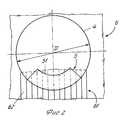
Ниже описан предпочтительный вариант осуществления настоящего изобретения со ссылками на прилагаемые чертежи, на которых: на фиг.1 представлено вертикальное сечение А-А фары; на фиг.2 представлен вид Р фазы в направлении светового луча; на фиг.3 представлено горизонтальное сечение В-В рефрактора фары; на фиг.4 представлена проекция световых лучей фары на проезжую часть. A preferred embodiment of the present invention is described below with reference to the accompanying drawings, in which: FIG. 1 is a vertical section AA of a headlamp; figure 2 presents a view of the phase P in the direction of the light beam; figure 3 presents a horizontal section bb of the headlight refractor; figure 4 presents the projection of the light rays of the headlights on the roadway.
Как можно видеть из чертежей и, в частности, из фиг.1, световой источник 2 фары расположен на оси 12 и вблизи от вершины 11 вогнутого (параболического) отражателя 1. Световой источник 2 образован поперечно или аксиально ориентированным телом приблизительно цилиндрической формы, например спиральной нитью лампы накаливания или другой разрядной трубки. За отражателем 1 следует экран 3, край 31 которого находится на одной горизонтали с противотуманной лампой и в то же время расходится с фарой ближнего света. Дальше от экрана 3 на расстоянии XF от него находится объектив 4 с диаметром D (фиг.2), который сконструирован для коллимации лучей 13, 14, идущих от отражателя 1. Ближе от объектива 4 у его нижней стороны находится отражательный сегмент 5, имеющий отражательную поверхность 51, находящуюся вблизи от упомянутого объектива 4, причем его угол наклона i5 соответствует уравнению:
i5 (2-1/2-21/2) агсtg (D/XF, (1)
где D диаметр объектива 4;
XF расстояние между экраном 3 и объективом 4.As can be seen from the drawings and, in particular, from FIG. 1, the light source 2 of the headlight is located on the axis 12 and close to the top 11 of the concave (parabolic) reflector 1. The light source 2 is formed by a transverse or axially oriented body of approximately cylindrical shape, for example a spiral filament of an incandescent lamp or other discharge tube. Behind the reflector 1 is a screen 3, the edge 31 of which is on the same horizontal line with a fog lamp and at the same time diverges from the dipped beam. Further from the screen 3 at a distance of XF from it there is a
i5 (2-1/2 -21/2 ) agstg (D / XF , (1)
where D is the diameter of the
XF distance between screen 3 and
Угол i5 либо постоянен в продольном направлении, либо изменяется в заданном диапазоне по длине, при этом вертикальный размер светового луча, формируемый им, может регулироваться. Отражательная поверхность 51 отражательного сегмента 5 либо симметрична в круговом направлении относительно оси 52 этого сегмента 5, либо планарна. Дальше от объектива 4 находится рефрактор 6, снабженный полосными линзами 62.The angle i5 is either constant in the longitudinal direction, or varies in a given range in length, while the vertical size of the light beam formed by it can be adjusted. The
На фиг. 2 показаны объектив 4, отражательный сегмент 5 и рефрактор 6 с зоной 61 полосных линз 62, при этом упомянутая зона 61 полностью или частично перекрывает отражательную поверхность 51 отражательного сегмента 5. Полосные линзы 62 рефрактора 6 располагаются примерно в вертикальном положении. In FIG. 2 shows a
Как можно видеть на фиг.3, сечение В-В рефрактора 6 в зоне 61 показывает отражательный профиль линз 62, ширина Н которого соответствует уравнению
H (0,2 21/2)•R, (2)
где R диаметр полосных линз 62.As can be seen in figure 3, the cross-section bb of the
H (0.2 21/2 ) • R, (2)
where R is the diameter of the
На проезжей части, содержащей осевую линию 81, левую обочину 82 и правую обочину 83, рисунок 4 показывает луч света 7, имеющий горизонтальную левостороннюю часть 71 границы света и темноты и правостороннюю часть 72, ломающуюся у этой границы при прохождении света, а также горизонтальную часть 73 с противотуманным светом. Лучи 15, 16, идущие от края отражателя 1, направляются отражательным сегментом 5 и объективом 4 в верхнюю половину пространства, где они образуют луч света 91. Полосные линзы 62 рефрактора 6 развивают упомянутый луч 91 в луч 92. Путем изменения бокового размера упомянутого луча 92 можно отрегулировать интенсивность освещения от оптимального значения как с точки зрения освещения, так и ослепления. On a roadway containing an
Фара согласно изобретению сконструирована для любых самоходных транспортных средств, работающих на суше. The headlamp according to the invention is designed for any land-based self-propelled vehicles.
Claims (6)
Translated fromRussiani5 = (2-1/2÷21/2)arctgD/xF,
где D диаметр объектива;
xF расстояние между экраном и объективом.1. A projection type headlight designed for self-propelled vehicles, containing a concave reflector for integrating light, a light source located in the interior of the reflector, a lens, a refractor and a screen located between the reflector and the lens, characterized in that it is equipped with a reflective segment with a reflective surface on the lens side, located between the screen and the lens, and the angle of inclination of the reflective surface i5 in vertical section corresponds to the following dependence
i5 = (2-1/2 ÷ 21/2 ) arctgD / xF ,
where D is the diameter of the lens;
xF is the distance between the screen and the lens.
H = (0,2-21/2)R,
где R диаметр полосных линз.2. The headlight according to claim 1, characterized in that the refractor is equipped with a band of lenses, which overlaps the lower part of the lens, and the width H of the band lenses corresponds to the ratio
H = (0.2-21/2 ) R,
where R is the diameter of the strip lenses.
Priority Applications (1)
| Application Number | Priority Date | Filing Date | Title |
|---|---|---|---|
| RU92004341ARU2070682C1 (en) | 1992-10-21 | 1992-10-21 | Search light type headlight for self-propelled vehicles |
Applications Claiming Priority (1)
| Application Number | Priority Date | Filing Date | Title |
|---|---|---|---|
| RU92004341ARU2070682C1 (en) | 1992-10-21 | 1992-10-21 | Search light type headlight for self-propelled vehicles |
Publications (2)
| Publication Number | Publication Date |
|---|---|
| RU92004341A RU92004341A (en) | 1995-01-20 |
| RU2070682C1true RU2070682C1 (en) | 1996-12-20 |
Family
ID=20131574
Family Applications (1)
| Application Number | Title | Priority Date | Filing Date |
|---|---|---|---|
| RU92004341ARU2070682C1 (en) | 1992-10-21 | 1992-10-21 | Search light type headlight for self-propelled vehicles |
Country Status (1)
| Country | Link |
|---|---|
| RU (1) | RU2070682C1 (en) |
Cited By (1)
| Publication number | Priority date | Publication date | Assignee | Title |
|---|---|---|---|---|
| RU2624908C1 (en)* | 2016-02-03 | 2017-07-10 | Акционерное общество "Научно-Производственный Комплекс "Альфа-М" | Dipped beam headlight |
- 1992
- 1992-10-21RURU92004341Apatent/RU2070682C1/enactive
Non-Patent Citations (1)
| Title |
|---|
| Патент ФРГ на полезную модель N 9000395, кл. F 21M 3/00, 1985.* |
Cited By (1)
| Publication number | Priority date | Publication date | Assignee | Title |
|---|---|---|---|---|
| RU2624908C1 (en)* | 2016-02-03 | 2017-07-10 | Акционерное общество "Научно-Производственный Комплекс "Альфа-М" | Dipped beam headlight |
Similar Documents
| Publication | Publication Date | Title |
|---|---|---|
| US5307247A (en) | Headlamp for motor vehicles | |
| US6919820B2 (en) | Vehicle headlamp system | |
| US7044624B2 (en) | Vehicle light with movable reflector portion and shutter portion for selectively switching an illuminated area of light incident on a predetermined portion of the vehicle light during driving | |
| KR100380500B1 (en) | Vehicle lamp apparatus | |
| EP0273353B1 (en) | Automotive headlight of projector type | |
| US7008093B2 (en) | Headlamp for vehicle | |
| KR20120050822A (en) | Head lamp assembly and method for controlling the same | |
| EP3660392A1 (en) | Lighting unit and vehicle headlight | |
| JP2753914B2 (en) | Automotive headlights | |
| US7021791B1 (en) | Vehicular headlamp apparatus | |
| US20030174493A1 (en) | Vehicular cornering lamp | |
| EP1234717B1 (en) | A headlight system preferably for motor vehicles | |
| US6913377B2 (en) | Projection-type vehicular headlamp | |
| US6543922B2 (en) | Vehicle lamp and vehicle lamp unit | |
| RU2115060C1 (en) | Vehicle head lamp | |
| US6558030B2 (en) | Elliptical headlight with beam modification by movement of optical elements | |
| KR20120011213A (en) | Car headlamps | |
| RU2070682C1 (en) | Search light type headlight for self-propelled vehicles | |
| US6612727B2 (en) | Lighting apparatus in a motor vehicle | |
| JP2003257215A (en) | Headlamp for vehicle | |
| EP1338468A2 (en) | Lighting fixture for vehicles | |
| EP1236613A2 (en) | Head lamp for vehicle | |
| JPS5952483B2 (en) | automotive headlights | |
| JPS6240481Y2 (en) | ||
| JPH0528644Y2 (en) |