RU2070006C1 - Intervertebral distractor - Google Patents
Intervertebral distractorDownload PDFInfo
- Publication number
- RU2070006C1 RU2070006C1RU93015856ARU93015856ARU2070006C1RU 2070006 C1RU2070006 C1RU 2070006C1RU 93015856 ARU93015856 ARU 93015856ARU 93015856 ARU93015856 ARU 93015856ARU 2070006 C1RU2070006 C1RU 2070006C1
- Authority
- RU
- Russia
- Prior art keywords
- levers
- vertebral
- pair
- attached
- axles
- Prior art date
Links
Images


Landscapes
- Prostheses (AREA)
- Surgical Instruments (AREA)
Abstract
Description
Translated fromRussianИзобретение относится к медицинской технике, а именно к устройствам для хирургического лечения повреждений и заболеваний позвоночника. The invention relates to medical equipment, namely to devices for the surgical treatment of injuries and diseases of the spine.
Известно устройство для стабилизации позвоночника (патент США N 4636217, A 61 F 2/44, 1987), имеющее остов, противоположные концы которого имеют плоскую концевую поверхность, относительно которой вводятся или вывинчиваются самофиксируемые костные винты. Костные винты находятся в каналах остова, их вращение осуществляется с помощью привода. A device for stabilization of the spine (US patent N 4636217, A 61 F 2/44, 1987), having a skeleton, the opposite ends of which have a flat end surface, relative to which self-locking bone screws are inserted or unscrewed are known. Bone screws are located in the channels of the skeleton, their rotation is carried out using a drive.
Однако известное устройство не устраняет осевую деформацию позвонков и не может использоваться для раздвигания тел позвонков до исходного уровня. However, the known device does not eliminate the axial deformation of the vertebrae and cannot be used to push the vertebral bodies to the initial level.
Известно устройство для стабилизации позвоночника (а.с. СССР N 1519677, A 61 B 17/60, 1989). Устройство содержит стержень с режущими выступами на контактной поверхности. Оно снабжено накладной пластинкой, фиксируемой к стержню винтами. Пластинка имеет продольные прорези, в гнездах которых установлены штанги с резьбой, причем каждая штанга имеет две опорные площадки с зубцами, ориентированными в противоположные стороны. Площадки установлены в пазах продольных прорезей с возможностью перемещения. A device is known for stabilization of the spine (as USSR N 1519677, A 61 B 17/60, 1989). The device comprises a rod with cutting protrusions on the contact surface. It is equipped with a patch plate fixed to the shaft with screws. The plate has longitudinal slots, in the sockets of which rods with a thread are installed, each rod having two supporting platforms with teeth oriented in opposite directions. The sites are installed in the grooves of the longitudinal slots with the ability to move.
Недостатком известного устройства является невозможность раздвигания позвонков и увеличения расстояния между ними при осевой и угловой деформациях. A disadvantage of the known device is the inability to push apart the vertebrae and increase the distance between them under axial and angular deformities.
Известно устройство для дистракции позвонков (патент США N 4553273, A 61 F 1/24, 1985), принятый за прототип. Устройство содержит опорные элементы и средство их разведения, выполненное в виде гайки, установленной на резьбовом стержне, и взаимодействующую c резьбовыми толкателями. A device for vertebral distraction is known (US patent N 4553273, A 61 F 1/24, 1985), adopted as a prototype. The device contains supporting elements and means for their breeding, made in the form of a nut mounted on a threaded rod, and interacting with threaded pushers.
Недостатками известного устройства являются малый запас хода при осевой дистракции позвонков, опасность самопроизвольного закручивания, углового смещения и повторного уменьшения расстояния между позвонками. The disadvantages of the known device are the small power reserve during axial distraction of the vertebrae, the danger of spontaneous twisting, angular displacement and repeated reduction of the distance between the vertebrae.
Изобретение направлено на создание межпозвонкового дистрактора, позволяющего раздвигать тела позвонков при больших угловых и осевых смещениях и при отсутствии одного, двух позвонков, сохранять постоянное расстояние дистракции и предотвращать опасность самопроизвольного углового смещения и уменьшения расстояния между позвонками. The invention is directed to the creation of an intervertebral distractor, allowing to extend the vertebral bodies at large angular and axial displacements and in the absence of one, two vertebrae, to maintain a constant distance of distraction and to prevent the danger of spontaneous angular displacement and reduce the distance between the vertebrae.
Сущность заявляемого изобретения заключается в том, что межпозвонковый дистрактор содержит опорные пластины и раздвижные элементы. Раздвижные элементы состоят из двух пар рычагов разной длины, которые соединены на осях в виде ромба. К одной паре рычагов прикреплены на осях верхняя и нижняя опорные пластины с шипами. К другой паре рычагов прикреплены направляющая планка и гайка с двумя резьбовыми отверстиями под винты. The essence of the claimed invention lies in the fact that the intervertebral distractor contains support plates and sliding elements. Sliding elements consist of two pairs of levers of different lengths, which are connected on the axes in the form of a rhombus. The upper and lower support plates with spikes are attached to one pair of levers on the axes. A guide bar and a nut with two threaded screw holes are attached to another pair of levers.
Изобретение отличается от прототипа тем, что раздвижные элементы содержат две пары рычагов, соединенных на осях в виде ромба, к одной паре рычагов на осях прикреплены опорные пластины с шипами, а к другой паре рычагов прикреплены направляющая планка и гайка с резьбовыми отверстиями под винты. The invention differs from the prototype in that the sliding elements contain two pairs of levers connected on the axes in the form of a rhombus, support plates with spikes are attached to one pair of levers on the axes, and a guide plate and a nut with threaded holes for screws are attached to the other pair of levers.
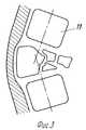
На фиг. 1, 2 изображен межпозвонковый дистрактор в двух проекциях; на фиг.3 5 схемы установки дистрактора. In FIG. 1, 2 shows the intervertebral distractor in two projections; figure 3 5 installation diagram of the distractor.
Межпозвонковый дистрактор состоит из пары длинных рычагов 1, пары коротких рычагов 2, которые на осях 3 соединены в виде ромба. К паре рычагов 1 на осях 4 прикреплены верхняя 5 и нижняя 6 опорные пластины с шипами 7. К паре рычагов 1, 2 прикреплены направляющая планка 8 и гайка 9 с двумя резьбовыми отверстиями под винты 10. The intervertebral distractor consists of a pair of
Межпозвонковый дистрактор применяется следующим образом. The intervertebral distractor is used as follows.
После резекции поврежденного в результате травмы или другого патологического процесса позвонка на его место устанавливают дистрактор. Опорные пластины 5 и 6 сведены. С помощью торцевого ключа через направляющую планку 8 в гайку 9 закручивают два винта 10. При этом раздвигаются опорные пластины 5 и 6 и раздвигают тела выше- и нижерасположенных позвонков. Благодаря этому исправляется ось позвоночника и устраняется компрессия спинного мозга. Шипы 7, внедряясь в тела смежных позвонков, надежно препятствуют горизонтальному и вертикальному смещению позвонков относительно друг друга. Крупные костные фрагменты резицированного позвонка укладывают с передне-боковой поверхности межпозвонкового дистрактора для образования костного блока и фиксируют лавсановыми нитями. After resection of a vertebra damaged as a result of an injury or other pathological process, a distractor is installed in its place.
Дистрактор может оставаться в организме человека пожизненно, обеспечивая надежную фиксацию и стабилизацию позвоночника или использоваться как приспособление для раздвигания позвонков в ходе операции с последующей заменой его на эндопротез позвонка. The distractor can remain in the human body for life, providing reliable fixation and stabilization of the spine or can be used as a device for expanding the vertebrae during surgery with its subsequent replacement with a vertebral endoprosthesis.
Claims (1)
Translated fromRussianPriority Applications (1)
| Application Number | Priority Date | Filing Date | Title |
|---|---|---|---|
| RU93015856ARU2070006C1 (en) | 1993-03-29 | 1993-03-29 | Intervertebral distractor |
Applications Claiming Priority (1)
| Application Number | Priority Date | Filing Date | Title |
|---|---|---|---|
| RU93015856ARU2070006C1 (en) | 1993-03-29 | 1993-03-29 | Intervertebral distractor |
Publications (2)
| Publication Number | Publication Date |
|---|---|
| RU93015856A RU93015856A (en) | 1995-07-27 |
| RU2070006C1true RU2070006C1 (en) | 1996-12-10 |
Family
ID=20139276
Family Applications (1)
| Application Number | Title | Priority Date | Filing Date |
|---|---|---|---|
| RU93015856ARU2070006C1 (en) | 1993-03-29 | 1993-03-29 | Intervertebral distractor |
Country Status (1)
| Country | Link |
|---|---|
| RU (1) | RU2070006C1 (en) |
Cited By (16)
| Publication number | Priority date | Publication date | Assignee | Title |
|---|---|---|---|---|
| RU2177273C2 (en)* | 2000-02-17 | 2001-12-27 | Галикеев Марат Фаритович | Device for distraction of vertebras |
| RU2200509C2 (en)* | 2001-02-27 | 2003-03-20 | Галикеев Марат Фаритович | Intervertebral distractor |
| RU2225183C2 (en)* | 2001-09-12 | 2004-03-10 | Галикеев Марат Фаритович | Wedging intervertebral distractor device |
| RU2423092C1 (en)* | 2009-07-17 | 2011-07-10 | Ульрих Гмбх Унд Ко. Кг | Element for spine traction |
| RU2443400C2 (en)* | 2007-03-07 | 2012-02-27 | Ульрих Гмбх Унд Ко. Кг | Intervertebral disk implant with elastic structural elements |
| RU2495648C2 (en)* | 2007-11-08 | 2013-10-20 | Спине21 Лтд. | Spine implant with adjustable postoperative dimensions |
| RU2497476C2 (en)* | 2009-03-12 | 2013-11-10 | Вексим | Apparatus for restoration of spine bones and methods of application |
| RU2506929C2 (en)* | 2011-03-14 | 2014-02-20 | Ульрих Гмбх Унд Ко. Кг | Implant |
| US10098751B2 (en) | 2004-06-09 | 2018-10-16 | Vexim | Methods and apparatuses for bone restoration |
| RU2714086C1 (en)* | 2016-08-11 | 2020-02-11 | Ульрих Гмбх Энд Ко. Кг | Prevention of vertebral implant compression |
| US10603080B2 (en) | 2013-12-23 | 2020-03-31 | Vexim | Expansible intravertebral implant system with posterior pedicle fixation |
| US10973650B2 (en) | 2015-12-30 | 2021-04-13 | Nuvasive, Inc. | Lordotic expandable fusion implant |
| US11234833B2 (en) | 2015-05-12 | 2022-02-01 | Nuvasive, Inc. | Expandable lordosis intervertebral implants |
| US11273047B2 (en) | 2017-12-18 | 2022-03-15 | Nuvasive, Inc. | Expandable implant device |
| US11679000B2 (en) | 2013-05-22 | 2023-06-20 | Nuvasive, Inc. | Expandable fusion implant and related methods |
| CN116616895A (en)* | 2023-05-18 | 2023-08-22 | 首都医科大学宣武医院 | A navigation and positioning structure for spinal surgery |
- 1993
- 1993-03-29RURU93015856Apatent/RU2070006C1/enactive
Non-Patent Citations (1)
| Title |
|---|
| 1. Патент США N 4636217, кл. A 61 F 2/44, 1987. 2. Авторское свидетельство СССР N 1519677, кл. A 61 B 17/76, 1989. 3. Патент США N 4553273, кл. A 61 F 1/24, 1985.* |
Cited By (23)
| Publication number | Priority date | Publication date | Assignee | Title |
|---|---|---|---|---|
| RU2177273C2 (en)* | 2000-02-17 | 2001-12-27 | Галикеев Марат Фаритович | Device for distraction of vertebras |
| RU2200509C2 (en)* | 2001-02-27 | 2003-03-20 | Галикеев Марат Фаритович | Intervertebral distractor |
| RU2225183C2 (en)* | 2001-09-12 | 2004-03-10 | Галикеев Марат Фаритович | Wedging intervertebral distractor device |
| US11752004B2 (en) | 2004-06-09 | 2023-09-12 | Stryker European Operations Limited | Systems and implants for bone restoration |
| US10813771B2 (en) | 2004-06-09 | 2020-10-27 | Vexim | Methods and apparatuses for bone restoration |
| US10098751B2 (en) | 2004-06-09 | 2018-10-16 | Vexim | Methods and apparatuses for bone restoration |
| RU2443400C2 (en)* | 2007-03-07 | 2012-02-27 | Ульрих Гмбх Унд Ко. Кг | Intervertebral disk implant with elastic structural elements |
| RU2495648C2 (en)* | 2007-11-08 | 2013-10-20 | Спине21 Лтд. | Spine implant with adjustable postoperative dimensions |
| RU2497476C2 (en)* | 2009-03-12 | 2013-11-10 | Вексим | Apparatus for restoration of spine bones and methods of application |
| RU2423092C1 (en)* | 2009-07-17 | 2011-07-10 | Ульрих Гмбх Унд Ко. Кг | Element for spine traction |
| RU2506929C2 (en)* | 2011-03-14 | 2014-02-20 | Ульрих Гмбх Унд Ко. Кг | Implant |
| US11957602B2 (en) | 2013-05-22 | 2024-04-16 | Nuvasive Inc. | Expandable fusion implant and related methods |
| US11679000B2 (en) | 2013-05-22 | 2023-06-20 | Nuvasive, Inc. | Expandable fusion implant and related methods |
| US10603080B2 (en) | 2013-12-23 | 2020-03-31 | Vexim | Expansible intravertebral implant system with posterior pedicle fixation |
| US11344335B2 (en) | 2013-12-23 | 2022-05-31 | Stryker European Operations Limited | Methods of deploying an intravertebral implant having a pedicle fixation element |
| US11998245B2 (en) | 2013-12-23 | 2024-06-04 | Stryker European Operations Limited | System including an intravertebral implant and a pedicle fixation for treating a vertebral body |
| US11234833B2 (en) | 2015-05-12 | 2022-02-01 | Nuvasive, Inc. | Expandable lordosis intervertebral implants |
| US11938040B2 (en) | 2015-05-12 | 2024-03-26 | Nuvasive, Inc. | Expandable lordosis intervertebral implants |
| US11690730B2 (en) | 2015-12-30 | 2023-07-04 | Nuvasive, Inc. | Lordotic expandable fusion implant |
| US10973650B2 (en) | 2015-12-30 | 2021-04-13 | Nuvasive, Inc. | Lordotic expandable fusion implant |
| RU2714086C1 (en)* | 2016-08-11 | 2020-02-11 | Ульрих Гмбх Энд Ко. Кг | Prevention of vertebral implant compression |
| US11273047B2 (en) | 2017-12-18 | 2022-03-15 | Nuvasive, Inc. | Expandable implant device |
| CN116616895A (en)* | 2023-05-18 | 2023-08-22 | 首都医科大学宣武医院 | A navigation and positioning structure for spinal surgery |
Similar Documents
| Publication | Publication Date | Title |
|---|---|---|
| RU2070006C1 (en) | Intervertebral distractor | |
| US11759331B2 (en) | Stabilized expandable intervertebral spacer | |
| US6626909B2 (en) | Apparatus and method for spine fixation | |
| Been et al. | Comparison of two types of surgery for thoraco-lumbar burst fractures: combined anterior and posterior stabilisation vs. posterior instrumentation only | |
| AU2009228030B2 (en) | Expandable cage with locking device | |
| EP0567424B1 (en) | Vertebral prosthesis for the substitution of a vertebra in malignant tumour surgery | |
| US4401112A (en) | Spinal fixator | |
| EP2323573B1 (en) | Anterior transpedicular screw-and-plate system | |
| US5735899A (en) | Low profile intraosseous anterior spinal fusion system and method | |
| EP1099428A2 (en) | Spine stabilization device | |
| AU4204896A (en) | Anterior screw-rod connector, formerly spinal rod transverse connectors | |
| EP1942816A2 (en) | Devices and methods for inter-vertebral orthopedic device placement | |
| EP0618785A4 (en) | ANTERIOR LOMBO-THORACIC PLATE. | |
| US20160331544A1 (en) | Spinal implant system and method | |
| RU93015856A (en) | INTERCONNECTIVE DISTRACTOR | |
| DE102016118642A1 (en) | Spinal device and procedure | |
| RU2099027C1 (en) | Kedrov's damping endoprostheses for vertebra | |
| RU2176907C2 (en) | Device for carrying out vertebral column osteosynthesis | |
| RU2063187C1 (en) | Endoprosthesis-distractor | |
| RU2028108C1 (en) | Method of transosseal fixation of vertebral column | |
| RU2055537C1 (en) | Device for correcting and stabilizing spinal column | |
| RU2051638C1 (en) | Device for fixing and correcting vertebral column deformations | |
| CN210121167U (en) | Can strut spinous process and fuse steel sheet fixed system | |
| KR100541413B1 (en) | Nerve pore expansion and soft spinal fixture | |
| RU2026025C1 (en) | Device for correction and stabilization of vertebral column |