RU2067775C1 - Device for reading pictures of objects - Google Patents
Device for reading pictures of objectsDownload PDFInfo
- Publication number
- RU2067775C1 RU2067775C1RU93021011ARU93021011ARU2067775C1RU 2067775 C1RU2067775 C1RU 2067775C1RU 93021011 ARU93021011 ARU 93021011ARU 93021011 ARU93021011 ARU 93021011ARU 2067775 C1RU2067775 C1RU 2067775C1
- Authority
- RU
- Russia
- Prior art keywords
- output
- coordinate
- input
- information
- switch
- Prior art date
Links
- 238000012545processingMethods0.000claimsdescription18
- 238000003825pressingMethods0.000claimsdescription3
- 230000000704physical effectEffects0.000abstractdescription2
- 230000000694effectsEffects0.000abstract1
- 238000004088simulationMethods0.000abstract1
- 239000000126substanceSubstances0.000abstract1
- 238000010586diagramMethods0.000description15
- 230000008859changeEffects0.000description14
- 238000000034methodMethods0.000description11
- 238000013461designMethods0.000description10
- 230000010365information processingEffects0.000description6
- 230000008569processEffects0.000description6
- 230000009471actionEffects0.000description4
- 238000005259measurementMethods0.000description4
- 230000003993interactionEffects0.000description3
- 239000000203mixtureSubstances0.000description3
- 239000007921spraySubstances0.000description3
- 238000012360testing methodMethods0.000description3
- 238000004364calculation methodMethods0.000description2
- 239000004020conductorSubstances0.000description2
- 230000006870functionEffects0.000description2
- 230000001939inductive effectEffects0.000description2
- 238000004519manufacturing processMethods0.000description2
- 238000001208nuclear magnetic resonance pulse sequenceMethods0.000description2
- 238000003491arrayMethods0.000description1
- 230000005540biological transmissionEffects0.000description1
- 230000015572biosynthetic processEffects0.000description1
- 230000000903blocking effectEffects0.000description1
- 238000006243chemical reactionMethods0.000description1
- 238000010276constructionMethods0.000description1
- 239000003814drugSubstances0.000description1
- 230000002996emotional effectEffects0.000description1
- 238000009434installationMethods0.000description1
- 239000000696magnetic materialSubstances0.000description1
- 239000003973paintSubstances0.000description1
- 230000035945sensitivityEffects0.000description1
- 238000012546transferMethods0.000description1
- 230000001131transforming effectEffects0.000description1
- 230000007704transitionEffects0.000description1
- 238000012795verificationMethods0.000description1
- 229910000859α-FeInorganic materials0.000description1
Images


Landscapes
- Position Input By Displaying (AREA)
Abstract
Description
Translated fromRussianИзобретение относится к области машинной графики, в частности к области оперативного отображения на электронных или электронно-оптических средствах графической информации, управление которой обеспечивается с помощью сенсорных кодирующих планшетов. The invention relates to the field of computer graphics, in particular to the field of operational display on electronic or electron-optical means of graphical information, the control of which is provided using touch coding tablets.
Создание графического произведения связано с выполнением художником таких операций, как перемещение графического инструмента по планшету и осуществление физического силового воздействия на инструмент, что обеспечивает регулирование параметров графического образа, например, таких параметров,как цвет рисуемой линии и ее толщина. В качестве графического инструмента могут использоваться кисть, карандаш, перо, пульверизатор, а также другие инструменты. В случае использования пульверизатора управляемыми параметрами может быть расстояние пульверизатора от плоскости, на которую наносится краска, что приводит одновременно к изменению размера пятна и его фактуры. The creation of a graphic work is associated with the artist performing such operations as moving a graphic tool on a tablet and exercising physical force on the tool, which provides regulation of the parameters of the graphic image, for example, parameters such as the color of the drawn line and its thickness. As a graphic tool, a brush, pencil, pen, spray gun, and other tools can be used. In the case of using a spray gun, the controlled parameters may be the distance of the spray gun from the plane onto which the paint is applied, which simultaneously leads to a change in the size of the spot and its texture.
Однако в основном управляющими параметрами являются величина давления, оказываемого рукой художника на графический инструмент (величина давления, оказываемого инструментом на планшет), а также угол наклона и деформированность пишущей части графического инструмента. However, the control parameters are mainly the amount of pressure exerted by the artist’s hand on the graphic instrument (the amount of pressure exerted by the instrument on the tablet), as well as the angle of inclination and deformation of the writing part of the graphic instrument.
Учитывая, что величина давления на графический инструмент в процессе рисования является существенным признаком, отражающим индивидуальное эмоциональное состояние художника и состояние графического инструмента, предлагается устройство для электронной художественной графики, в котором объединены электронный графический планшет, оснащенный, например, средством для определения координаты карандаша-указателя, устройство для измерения величины силового воздействия на карандаш-указатель, персональная ЭВМ, оснащенная программными средствами поддержания графических режимов и устройство вывода твердой копии. Устройство обеспечивает плавное оперативное управление одним или несколькими параметрами графического образа. Considering that the amount of pressure on a graphic tool in the process of drawing is an essential feature that reflects the individual emotional state of the artist and the state of the graphic tool, a device for electronic art graphics is proposed that combines an electronic graphic tablet equipped with, for example, means for determining the coordinates of a pointer , a device for measuring the magnitude of the force acting on a pencil-pointer, a personal computer equipped with software environments Tvam maintain graphic modes and a hard copy output device. The device provides smooth operational control of one or more parameters of the graphic image.
В качестве параметров графического образа могут быть выбраны цвет, фактура или геометрические параметры рисуемого графического образа. As the parameters of the graphic image, the color, texture or geometric parameters of the drawn graphic image can be selected.
В настоящее время известны подобные устройства, обеспечивающие создание оригинальных чертежей и рисунков, гравюр, ретуширование фотографий. Основным элементом таких устройств является сенсорный кодирующий планшет. Художнику-графику при создании картин данные цифровые преобразователи дают два важных преимущества:
-инструмент, которым он пользуется,имеет привычные размеры рабочего поля и форму пера или карандаша,с которым работать гораздо естественнее, чем с "мышью", используемой обычно для ввода графической информации в ПЭВМ;
электронное "перо", применяемое в современных цифровых преобразователях, подобно традиционным инструментам, таким как кисть и карандаш, и не стесняет движения руки художника;
"перо" "понимает",с какой силой вы надавливаете его кончиком на поверхность планшета, который определяет текущее положение пера, при этом проводимая линия или другой графический образ изменяется (меняя толщину, цвет или фактуру), как при работе обычным графическим инструментом.Currently, such devices are known that provide the creation of original drawings and drawings, prints, photo retouching. The main element of such devices is a touch coding tablet. When creating a graphic artist, these digital converters provide two important advantages:
-the tool that he uses has the usual dimensions of the working field and the shape of a pen or pencil, which is much more natural to work with than the "mouse", which is usually used to enter graphic information into a PC;
electronic "pen" used in modern digital converters, like traditional tools, such as a brush and pencil, and does not restrict the movement of the artist's hand;
The “pen” “understands” the force with which you push it with the tip on the surface of the tablet, which determines the current position of the pen, while the line or other graphic image changes (changing thickness, color or texture), as when using a regular graphic tool.
Известен портативный графический аппарат, запатентованный в Японии, который приспособлен для выполнения графических работ [1]
Устройство снабжено тактильным планшетом, перемещение по которому пера или пальца преобразуется в линию на экране телемонитора, при этом линия рисуется на экране только до тех пор, пока пользователь касается планшета.Known portable graphic device, patented in Japan, which is adapted to perform graphic work [1]
The device is equipped with a tactile tablet, the movement of which a pen or finger is converted into a line on the screen of the television monitor, while the line is drawn on the screen only as long as the user touches the tablet.
Дополнительными кнопками на планшете можно выбирать вид графического инструмента, цвет линии, ее ширину, а также режим редактирования рисунка. Additional buttons on the tablet, you can choose the type of graphic tool, the color of the line, its width, as well as the editing mode of the picture.
Однако в данном устройстве такие параметры графического образа как ширина линии, ее цвет, фактура задаются дискретными значениями, при этом отсутствует возможность непрерывно изменять хотя бы один из этих параметров. Смена значений параметров происходит с помощью специальных клавиш, ограниченное число которых существенно сужает возможности художника при выполнении им графических работ. However, in this device, such parameters of the graphic image as the line width, its color, texture are set by discrete values, while it is not possible to continuously change at least one of these parameters. Changing the values of the parameters occurs with the help of special keys, a limited number of which significantly narrows the artist's abilities when he performs graphic works.
Другим известным техническим устройством является электронная графическая доска производства Японии [2]
Устройство содержит планшет, обеспечивающий считывание координат карандаша-указателя, соединенного с планшетом кабелем.Another well-known technical device is an electronic graphic board made in Japan [2]
The device includes a tablet, providing the reading of the coordinates of a pencil-pointer connected to the tablet with a cable.
Планшет в свою очередь соединен с ЭВМ, оснащенной дисплеем, на котором осуществляется отображение графической информации. С помощью специализированных программных средств поддерживаются графические режимы выбора ширины линии, ее цвета, фактуры, а также выбор графического инструмента такого, как карандаш, перо, кисть и т.д. The tablet, in turn, is connected to a computer equipped with a display on which graphic information is displayed. Using specialized software tools, graphic modes for selecting the line width, its color, texture, as well as the choice of a graphic tool such as a pencil, pen, brush, etc. are supported.
В данном графическом устройстве возможно задание широкого диапазона изменения параметров таких, как ширина линии, ее цвет, фактура. При рисовании выбор конкретного параметра осуществляется через графическое меню, высвечиваемое на экране монитора. Операция выбора заключается в подводе (с помощью карандаша-указателя) курсора к выбираемому значению параметра в соответствующей зоне меню, фиксации этого значения до следующей смены параметров. Недостатком устройства является необходимость прерывания процесса рисования для смены режима рисования. Указанные действия приводят к усложнению таких процессов рисования, как выполнение, например, рисунка линией переменной толщины и цвета. In this graphic device, it is possible to set a wide range of parameter changes such as line width, color, texture. When drawing, a specific parameter is selected through the graphical menu displayed on the monitor screen. The selection operation consists in approaching (using a pointer) the cursor to the selected parameter value in the corresponding menu area, fixing this value until the next change of parameters. The disadvantage of this device is the need to interrupt the drawing process to change the drawing mode. These actions complicate drawing processes such as, for example, drawing a line with a variable thickness and color.
Наиболее близким техническим решением к предлагаемому изобретению, выбранным в качестве прототипа, относится "Координатная система ввода с пером ввода", разработанная фирмой Wacom Technoloqy Inc японских изобретателей: Yamanami, Funahashi, Senda, Chikami [3]
Данное устройство содержит планшет для снятия координат указателя, кроме того, в указатель встроен резонансный контур, содержащий индуктивный датчик, измеряющий положение контактного стержня с ферритовыми сердечниками, один из концов которого подпружинен, а другой является опорным элементом указателя.The closest technical solution to the proposed invention, selected as a prototype, is the "Coordinate input system with an input pen" developed by Wacom Technoloqy Inc of Japanese inventors: Yamanami, Funahashi, Senda, Chikami [3]
This device contains a tablet for taking the coordinates of the pointer, in addition, a resonant circuit is included in the pointer, containing an inductive sensor that measures the position of the contact rod with ferrite cores, one of the ends of which is spring-loaded, and the other is a supporting element of the pointer.
Сигналы от координатного планшета и индуктивного датчика поступают в ЭВМ и преобразуются в положение рисуемого элемента линии и его толщину. The signals from the coordinate tablet and the inductive sensor enter the computer and are converted to the position of the drawn line element and its thickness.
Недостатком устройства является значительное линейное перемещение контактного стержня, встроенного в указатель в диапазоне 1,5-3 мм, что требует приобретения специальных навыков рисования. The disadvantage of this device is the significant linear movement of the contact rod, built into the pointer in the range of 1.5-3 mm, which requires the acquisition of special drawing skills.
Другим недостатком устройства является измерение силы давления только вдоль продольной оси указателя, что ограничивает возможности имитации широкого набора графических инструментов таких, как кисть, "мастехин", различные виды перьев и возможности моделирования различных технических приемов рисования, а также уменьшает чувствительность пера к величине давления при малых наклонах пера относительно рабочей поверхности. Another disadvantage of the device is the measurement of pressure only along the longitudinal axis of the pointer, which limits the ability to simulate a wide range of graphical tools, such as a brush, a master, various types of pens and the ability to simulate various drawing techniques, and also reduces the sensitivity of the pen to pressure small inclinations of the pen relative to the working surface.
Предлагаемое в изобретении устройство позволяет сохранить традиционные навыки рисования карандашом-указателем, осуществляя его перемещение и изменяя величину силового воздействия на указатель, которая в дальнейшем преобразуется в параметры графического образа. The device proposed in the invention allows preserving the traditional skills of drawing with a pencil-pointer, moving it and changing the magnitude of the force acting on the pointer, which is subsequently converted into the parameters of the graphic image.
Основные достоинства предлагаемого устройства:
возможность одновременного изменения нескольких параметров графического образца путем использования одного или нескольких датчиков силы для измерения величины контактного взаимодействия, что обеспечивает имитацию широкого круга графических инструментов;
использование жесткого "пера", не имеющего в составе конструкции подвижных элементов, что обеспечивает использование традиционных навыков рисования;
возможность использования указателя для перемещения трехмерных объектов в трехмерной сцене даже при его неподвижном положении, а также возможность использования параметров положения пера относительно планшета в качестве параметров графического инструмента, меняющих одновременно, например, ракурс наблюдения графического образа или его цвет и яркость.The main advantages of the proposed device:
the ability to simultaneously change several parameters of a graphic sample by using one or more force sensors to measure the magnitude of the contact interaction, which provides an imitation of a wide range of graphic tools;
the use of a hard "pen" that does not have movable elements in the structure, which ensures the use of traditional drawing skills;
the ability to use the pointer to move three-dimensional objects in a three-dimensional scene even when it is stationary, as well as the ability to use the pen position relative to the tablet as parameters of a graphic tool that simultaneously change, for example, the viewing angle of a graphic image or its color and brightness.
Устройство для электронной художественной графики содержит как и в прототипе:
планшет с системой взаимоортогональных шин и расположенной над ними контактной поверхностью;
коммутаторы координаторных шин по осям Х, У, входы которых соединены соответственно с координатными шинами Х и У, а выходы соединены через усилители координатных шин с первым и вторым входами блока обработки координатной информации, первый и второй выходы которого соединены с адресными входами коммутаторов, координатных шин, блок управления, связанный входами и выходами 1-3 соответственно, с блоком обработки координатной информации, управляющей ЭВМ и импульсным генератором, первый выход которого соединен с третьим входом блока обработки координатной информации.The device for electronic art graphics contains, as in the prototype:
a tablet with a system of mutually orthogonal tires and a contact surface located above them;
coordinator bus switches along the X and Y axes, the inputs of which are connected respectively to the coordinate buses X and Y, and the outputs are connected via coordinate bus amplifiers to the first and second inputs of the coordinate information processing unit, the first and second outputs of which are connected to the address inputs of the commutators, coordinate buses , a control unit connected by inputs and outputs 1-3, respectively, with a coordinate information processing unit controlling a computer and a pulse generator, the first output of which is connected to the third input of the processing unit coordinate information.
cъемник координат, содержит контактный стержень и катушку, индуктивно связанную с координатными шинами. coordinate remover, contains a contact rod and a coil inductively coupled to the coordinate buses.
Основные отличия предлагаемого устройства состоят в том, что в состав устройства введены:
датчик усилия нажатия;
блок обработки сигналов с датчиков усилия нажатия (микро-ЭВМ, оснащенная встроенной памятью программ, памятью данных и портами ввода-вывода);
блок постоянной памяти (ПЗУ), предназначенный для хранения функциональных зависимостей, обеспечивающих реализацию различных типов графических инструментов и задаваемых при изготовлении устройства;
блок оперативной памяти (ОЗУ), предназначенный для хранения функциональных зависимостей, обеспечивающих реализацию различных типов графических инструментов которые задаются и оперативно изменяются пользователем при эксплуатации устройства;
аналого-цифровой преобразователь (АЦП);
усилители электрических сигналов с датчиков усилия нажатия;
коммутатор электрических сигналов;
буферный усилитель;
механический переключатель.The main differences of the proposed device are that the composition of the device introduced:
pressure sensor;
a unit for processing signals from pressure sensors (micro-computers equipped with built-in program memory, data memory and input-output ports);
a permanent memory unit (ROM), designed to store functional dependencies that provide the implementation of various types of graphical tools and specified during the manufacture of the device;
random access memory (RAM), designed to store functional dependencies that provide the implementation of various types of graphical tools that are set and quickly changed by the user during operation of the device;
analog-to-digital converter (ADC);
amplifiers of electrical signals from pressure sensors;
electrical signal switch;
buffer amplifier;
mechanical switch.
При этом входы и выходы 1-4 блока обработки сигналов датчиков усилия нажатия соединены соответственно со входами и выходами блока управления, ПЗУ, АЦП и ОЗУ, вторые входы и выходы которого соединены с четвертыми входами и выходами блока управления. Выход переключателя, установленного на корпусе съемника координат, соединен с первым информационным входом коммутатора, выход которого через буферный усилитель соединен с пятым входом блока обработки сигналов с датчиков усилия нажатия, пятый выход которого соединен с управляющим входом коммутатора. The inputs and outputs 1-4 of the signal processing unit of the pressure sensor are connected respectively to the inputs and outputs of the control unit, ROM, ADC and RAM, the second inputs and outputs of which are connected to the fourth inputs and outputs of the control unit. The output of the switch mounted on the housing of the coordinate puller is connected to the first information input of the switch, the output of which through the buffer amplifier is connected to the fifth input of the signal processing unit from the pressure sensors, the fifth output of which is connected to the control input of the switch.
Выходы датчиков усилия нажатия через усилители с датчиков усилия нажатия соединены со свободными информационными входами коммутатора, выход которого соединен со входом АЦП. Катушка индуктивности подключена ко второму выходу импульсного генератора. The outputs of the pressure sensors through amplifiers from the pressure sensors are connected to the free information inputs of the switch, the output of which is connected to the input of the ADC. An inductor is connected to the second output of the pulse generator.
Одни из вариантов конструкции съемника координат, согласно настоящему изобретению, содержит датчик усилия нажатия, установленный вдоль продольной оси указателя и закрепленный между внутренней торцевой частью корпуса съемника координат и концом стержня, противоположным пишущему концу, и механически связанный с контактным стержнем, также установленным в корпусе вдоль его продольной оси. One of the design options for the coordinate remover, according to the present invention, comprises a pressure sensor mounted along the longitudinal axis of the pointer and secured between the inner end of the coordinate element and the end of the rod opposite the writing end, and mechanically connected with the contact rod, also installed in the housing along its longitudinal axis.
При этом датчик усилия нажатия выполнен в виде торцевых пластин, скрепленных по боковым поверхностям гибкими тонкостенными элементами, на боковой поверхности которых укреплены преобразователи деформации в электрический сигнал. In this case, the pressure sensor is made in the form of end plates fastened on the lateral surfaces by flexible thin-walled elements, on the lateral surface of which are transformers of deformation into an electrical signal.
Данное устройство отличается от известных технических решений тем, что на основании показаний одного датчика, но по разным функциональным зависимостям формируются несколько параметров, которые затем преобразуются в изменяемые одновременно параметры графического образа такие,как, например, ширина линии, ее цвет и фактура. This device differs from well-known technical solutions in that, based on the readings of one sensor, but according to different functional dependencies, several parameters are formed, which are then converted into simultaneously changing parameters of the graphic image, such as, for example, line width, color and texture.
Другим техническим решением, направленным на расширение функциональных возможностей графического устройства, является установка внутри корпуса съемника координат в зоне размещения катушки индуктивности датчиков измерения усилий нажатия по направлениям,перпендикулярным продольной оси корпуса указателя, выполненных в виде гибких тонкостенных элементов, одним концом скрепленных с корпусом указателя, а другим механически связанных со стержнем, при этом каждый элемент имеет плоскость симметрии, проходящую через продольную ось съемника координат, а на его боковой поверхности закреплены преобразователи деформации в электрический сигнал. Another technical solution aimed at expanding the functionality of a graphic device is to install coordinates inside the stripper housing in the area of the inductance coil of sensors for measuring pressure efforts in directions perpendicular to the longitudinal axis of the pointer housing, made in the form of flexible thin-walled elements, one end fastened to the pointer housing, and another mechanically connected with the rod, with each element having a plane of symmetry passing through the longitudinal axis of the puller and coordinates, and on its lateral surface are fixed deformation converters into an electrical signal.
С помощью данного устройства можно одновременно изменять несколько графических параметров рисуемого элемента. Так, при выборе в качестве исходного графического элемента окружности под действием управляющих силовых воздействий ее форма может видоизменяться в овал. При этом величина радиуса исходной окружности изменяется пропорционально величине проекции силы на продольную ось указателя, а ориентация оси овала и его длина определяются составляющими силового воздействия на указатель, перпендикулярными его продольной оси. Следовательно,управляющими графическими параметрами являются радиус исходной окружности R, ориентация оси овала f и длина овала L. Using this device, you can simultaneously change several graphic parameters of the element being drawn. So, when a circle is selected as the initial graphic element under the influence of controlling force actions, its shape can change into an oval. The radius of the original circle changes in proportion to the projection of the force on the longitudinal axis of the pointer, and the orientation of the axis of the oval and its length are determined by the components of the force acting on the pointer perpendicular to its longitudinal axis. Therefore, the control graphic parameters are the radius of the original circle R, the orientation of the axis of the oval f and the length of the oval L.
Наличие уже трех составляющих силы позволяет имитировать различные типы графических элементов и соответственно изменять технику рисования. The presence of already three components of the force allows you to simulate various types of graphic elements and, accordingly, change the technique of drawing.
Кроме этого, появляется возможность перемещения объекта в трехмерном пространстве, надавливая на указатель, закрепленный в одной точке планшета, преобразуя проекции силы, например, в координаты центра масс перемещаемого тела. In addition, it becomes possible to move an object in three-dimensional space by pressing on a pointer fixed at one point on the tablet, transforming the projection of the force, for example, into the coordinates of the center of mass of the moving body.
Одной из разновидностей предлагаемого устройства является создание съемника координат со съемным стержнем. При этом контактная поверхность стержня и ее механические свойства соответствуют форме и механическим свойствам какого-либо графического инструмента, а на боковой поверхности стержня, размещенной в корпусе указателя,нанесен код типа используемого графического инструмента. В корпусе cъемника координат установлено устройство считывания этого кода, соединенное через коммутатор и буферный усилитель с блоком обработки сигналов с датчиков усилия нажатия. One of the varieties of the proposed device is the creation of a coordinate remover with a removable rod. In this case, the contact surface of the rod and its mechanical properties correspond to the shape and mechanical properties of a graphic tool, and a type code of the used graphic tool is applied on the side surface of the rod placed in the pointer body. A reader of this code is installed in the housing of the coordinate puller, connected via a switch and a buffer amplifier to a signal processing unit from pressure sensors.
Такое устройство позволяет рисующему почувствовать особенности контактного взаимодействия планшета и имитируемого графического инструмента. Наличие съемного стержня приводит к необходимости проведения операции калибровки датчиков силы после смены стержня. Поэтому в качестве улучшенного варианта исполнения устройства предлагается менять не стержень, а контактный модуль, в корпусе которого размещены: катушка индуктивности, контактный стержень, датчики измерения сил и усилители электрических сигналов с этих датчиков. Such a device allows the drawer to feel the features of the contact interaction of the tablet and the simulated graphic tool. The presence of a removable rod makes it necessary to perform the calibration of force sensors after changing the rod. Therefore, as an improved embodiment of the device, it is proposed to change not the rod, but the contact module, in the housing of which are located: inductor, contact rod, force measurement sensors and amplifiers of electrical signals from these sensors.
При этом датчики измерения сил по направлениям, перпендикулярным продольной оси, выполнены в виде тонкостенных элементов, один конец которых закреплен внутри корпуса, а другой механически связан с контактным стержнем. В части корпуса контактного модуля, вставленной в корпус указателя, размещен электроразъем. Наличие такой конструкции съемника координат позволяет откалибровать датчики измерения усилия при изготовлении устройства, что упрощает процесс эксплуатации при частой смене контактных модулей. In this case, force measurement sensors in directions perpendicular to the longitudinal axis are made in the form of thin-walled elements, one end of which is fixed inside the housing, and the other is mechanically connected to the contact rod. An electrical connector is placed in a part of the housing of the contact module inserted into the pointer housing. The presence of such a design of the stripper coordinates allows you to calibrate the force measurement sensors in the manufacture of the device, which simplifies the process of operation with frequent changes of contact modules.
С целью расширения функциональных возможностей устройства, в одном из вариантов, предполагается установка на стержне, в зоне контакта с планшетом, нескольких датчиков измерения сил контактного взаимодействия, соединенных с усилителями сигналов датчиков усилия. Наличие этих датчиков позволяет, например, осуществлять изменение цвета внутри одного графического элемента, имитируя такой графический инструмент как мастехин. In order to expand the functionality of the device, in one of the options, it is planned to install on the rod, in the zone of contact with the tablet, several sensors for measuring the forces of contact interaction connected to amplifiers of the signals of the force sensors. The presence of these sensors allows, for example, to carry out a color change within a single graphic element, simulating a graphic tool such as a mastechin.
Для повышения комфорта при использовании устройства в его состав может быть введена клавиатура управления режимами генерации параметров графического инструмента и индикаторное табло отображения текущего состояния устройства и режима генерации параметров графического инструмента, соединенные с блоком обработки сигналов датчиков силы. To increase comfort when using the device, a keyboard for controlling the parameters of generating the parameters of the graphic instrument and an indicator board displaying the current state of the device and the mode of generating parameters of the graphical instrument connected to the signal processing unit of the force sensors can be introduced into its composition.
На фиг.1 представлен внешний вид графического устройства;
на фиг.2 функциональная схема устройства для электронной художественной графики; на фиг.3 конструкции съемника координат с однокомпонентным датчиком силы; на фиг.4 конструкция однокомпонентного датчика; на фиг.5 конструкция съемника координат с 3-х компонентным датчиком и пассивными сменными модулями; на фиг.6 конструкция датчика поперечных усилий нажатия; на фиг.7 схема считывания кода номера контактного стержня; на фиг.8 конструкция съемника координат с активными сменными насадками; на фиг.9 конструкция сменного модуля; на фиг.10 функциональная схема устройства, оснащенного блоком считывания кода номера сменного стержня (насадки), клавиатурой и индикаторным табло; на фиг.11 блок-схема алгоритма работы блока обработки сигналов с датчиков усилий нажатия; на фиг.12 блок-схема работы блока управления; на фиг. 13 блок-схема алгоритма определения кода насадки; на фиг.14 блок-схема алгоритма определения состояния датчиков силы; на фиг.15 блок-схема алгоритма формирования данных для управления параметрами графического образа; на фиг. 16 блок-схема алгоритма построения линии переменной толщины цвета и фактуры; на фиг. 17 схематичное изображение элементов линии переменной толщины; на фиг.18 схематичное изображение элементов линии переменной толщины и фактуры; на фиг. 19 пример результата работы программы с пейзажем; на фиг.20 пример результата работы программы со шрифтом.Figure 1 presents the appearance of the graphics device;
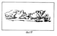
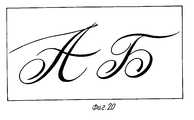
figure 2 is a functional diagram of a device for electronic art graphics; figure 3 of the design of the stripper coordinates with a one-component force sensor; figure 4 the design of a single-component sensor; figure 5 the design of the stripper coordinates with a 3-component sensor and passive replaceable modules; Fig.6 design of the sensor transverse pressing forces; 7 is a diagram for reading the code of the number of the contact rod; on Fig design of a stripper coordinates with active interchangeable nozzles; figure 9 the design of the replaceable module; figure 10 is a functional diagram of a device equipped with a code reader for a number of a replaceable rod (nozzle), a keyboard and an indicator board; figure 11 is a block diagram of the algorithm of the processing unit of the signals from the sensors of pressure efforts; on Fig block diagram of the operation of the control unit; in FIG. 13 is a flow chart of a nozzle code determination algorithm; on Fig block diagram of the algorithm for determining the state of the force sensors; on Fig block diagram of the data generation algorithm for controlling the parameters of the graphic image; in FIG. 16 is a flowchart of an algorithm for constructing a line of variable color thickness and texture; in FIG. 17 is a schematic illustration of line elements of variable thickness; Fig. 18 is a schematic illustration of line elements of variable thickness and texture; in FIG. 19 an example of the result of a program with a landscape; on Fig an example of the result of the program with the font.
Теперь опишем предпочтительный вариант осуществления изобретения. We now describe a preferred embodiment of the invention.
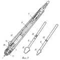
На фиг.1 изображено общее размещение элементов устройства для электронной художественной графики, содержащее съемник координат 1, соединенный с планшетом 2, который в свою очередь состыкован с ЭВМ 3, связанной информационными каналами с устройством вывода 4 и устройством отображения 5. Figure 1 shows the general arrangement of the elements of the device for electronic art graphics, containing a coordinate
На фиг.2 показана функциональная схема устройства для электронной художественной графики, на которой в состав съемника координат 1 введены контактный стержень 6, датчика усилия нажатия 7, усилители сигналов с датчиков усилителя нажатия 8, коммутатор 9, переключатель 10, катушка индуктивности 11. Figure 2 shows a functional diagram of a device for electronic art graphics, on which a
В состав планшета 2 входят:
система взаимоортогональных координатных шин 12, с расположенной над ними контактной поверхностью 13;
коммутаторы 14 и 15 координатных шин по осям Х и Y, входы которых соединены, соответственно, с координатными шинами Х и Y, а выходы соединены через усилители 16 сигналов с шин с первым и вторым входом блока обработки координатной информации 17, первый и второй выходы которого соединены с адресными входами коммутаторов координатных шин 14 и 15;
блок управления 18, связанный входами и выходам 1-3, соответственно, с блоком обработки координатной информации 17, управляющей ЭВМ 3 и импульсным генератором 19, первый выход которого соединен с третьим входом блока обработки координатной информации 17, а второй выход подключен к катушке индуктивности 11, установленной в съемнике координат 1;
блок 20 обработки сигналов с датчиков усилия нажатия;
оперативное запоминающее устройство (ОЗУ) 21;
постоянное запоминающее устройство (ПЗУ) 22;
аналогово-цифровой преобразователь 23;
буферный усилитель 24.The composition of the
a system of mutually orthogonal coordinate
switches 14 and 15 of the coordinate buses along the X and Y axes, the inputs of which are connected, respectively, with the coordinate buses X and Y, and the outputs are connected through
the
random access memory (RAM) 21;
read only memory (ROM) 22;
analog-to-
При этом входы и выходы 1-4 блока 20 обработки сигналов датчиков усилия нажатия соединены соответственно со входами и выходами блока управления, ПЗУ, АЦП и ОЗУ, вторые входы и выходы которого соединены с четвертыми входами и выходами блока управления. Выход переключателя 10 соединен с первым информационным входом коммутатора 9, выход которого через буферный усилитель 24 соединен с пятым входом блока 20 обработки сигналов датчиков усилия, пятый выход которого соединен с управляющим входом коммутатора 9. In this case, the inputs and outputs 1-4 of the signal processing sensor
Выходы датчиков 7 через усилитель 8 соединены со свободными информационными входами коммутатора 9, выход которого соединен с входом АЦП, а катушка 11 подключена ко второму входу импульсного генератора 19. Катушка 11 индуктивно связана с координатными шинами планшета. Контактный стержень 6, выступающий из корпуса съемника координат 1 с одной стороны, с другой находится в контакте по крайней мере с одним датчиком усилия. При этом катушка 11 размещена на конце стержня 6 в непосредственной близости от его контактной поверхности. The outputs of the
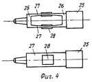
На фиг. 3 изображена конструкция указателя с однокомпонентным датчиком усилия 7. В данном техническом решении стержень 6, выполненный из немагнитного материала, проходит вдоль продольной оси указателя внутри катушки 1 индуктивности, закрепленной внутри корпуса съемника координат, вблизи контактной поверхности стержня 6, противоположный конец которого находится в контакте с торцом датчика 7, установленным также по продольной оси съемника координат и закрепленном своим вторым торцом в торцевой части 25 корпуса, в отверстии на боковой поверхности которого установлен переключатель 10. In FIG. 3 shows the design of the pointer with a one-
На фиг. 4 показан пример конструктивного выполнения однокомпонентного датчика 7, выполненный в виде балки, имеющей жесткие торцевые пластины 26, скрепленные по боковым поверхностям гибкими тонкостенными элементами 27, на боковой поверхности которых укреплены преобразователем 28 деформации в электрический сигнал. In FIG. 4 shows an example of a structural embodiment of a one-
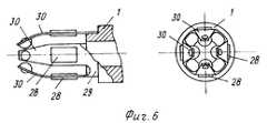
Для регистрации силы давления на съемник координат в направлениях,перпендикулярных его оси, предлагается техническое решение, представленное на фиг. 5, где показан вид, в который дополнительно к однокомпонентному датчику 7 установлен двухкомпонентный датчик 29. To register the pressure force on the coordinate puller in directions perpendicular to its axis, a technical solution is proposed, which is shown in FIG. 5, where a view is shown in which, in addition to the one-
Этот датчик (фиг.5, фиг.6) установлен внутри корпуса указателя 1 в зоне размещения катушки индуктивности и выполнен в виде гибких тонкостенных элементов 30, при этом плоскости симметрии двух соседних элементов взаимоортогональны, а на их боковой поверхности закреплены преобразователи 28 информации о силе давления в электрические силы. Тонкостенные элементы одним концом скреплены с корпусом, а другим механически связаны со стержнем 6, который воздействует на свободные концы упругих тонкостенных элементов. This sensor (Fig. 5, Fig. 6) is installed inside the
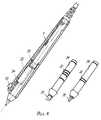
Для имитации геометрических и механических свойств используемого графического инструмента контактный стержень 6 может быть выполнен съемным (фиг. 5), при этом контактная поверхность 31 стержня 6 и ее механические свойства соответствуют форме и механическим свойствам имитируемого графического инструмента, а на боковой поверхности стержня 6, размещенной в корпусе, нанесен код 32 типа графического инструмента, при этом в корпусе (фиг.5, фиг.10) установлен блок 33 считывания этого кода (фиг.7), соединенный через коммутатор 9 и буферный усилитель 24. Блок-схема этого устройства приведена на фиг.9. To simulate the geometric and mechanical properties of the used graphic tool, the
Наличие контактного модуля 34 (фиг.8), в корпусе которого (фиг.9) размещены катушка индуктивности 11, контактный стержень 6, датчики 7 и усилители 8, стыкуемая со съемником координат 1 при помощи электроразъема 35 позволяет повысить качество настройки съемных элементов. The presence of the contact module 34 (Fig. 8), in the housing of which (Fig. 9) an
Для повышения комфорта оператора, работающего с устройством, в состав планшета (фиг.1) введена клавиатура 36 управления режимами генерации параметров графического инструмента и индикаторное табло 37 отображения текущего состояния устройства и режима генерации параметров графического инструмента. To increase the comfort of the operator working with the device, a
Устройство работает следующим образом. The device operates as follows.
Оператор осуществляет комбинированное воздействие на графический съемник координат 1, перемещая его по контактной поверхности 13 планшета 2. Установленный в планшете 2 генератор 19 вырабатывает импульсы, поступающие по кабелю в катушку 11, установленную в съемнике 1. Излучаемый катушкой 11 синусоидальный сигнал поочередно принимается координатными шинами по осям Х и Y системы 12 и через коммутаторы 14 и 15 и усилители 16 сигналов передается на вход блока определения координат 17, который осуществляет обработку наведенного катушкой 11 сигнала с целью формирования значений грубого и точного отсчетов по каждой координате. Грубый отсчет определяется сменой фазы сигнала, наведенного катушкой в соседних координатных линиях. Для определения точного отсчета используется один из известных методов, например метод, основанный на определении усредненных амплитуд сигналов, наведенных в соседних координатных шинах, или метод,основанный на измерении разницы фаз наведенных сигналов. Полученные значения грубого и точного отсчетов передаются затем в блок управления 18, обеспечивающий их цифровую обработку и вычисление значений полных координат указателя. The operator performs a combined action on the graphic remover of
Физическое воздействие, создаваемое оператором при помощи съемника координат на контактную поверхность 13 планшета, воспринимается через стержень 6 указателя датчиками 7 и преобразуется ими в электрический сигнал, который передается через усилители сигналов 8, коммутатор 9, по кабелю на вход АЦП 23. The physical effect created by the operator using the coordinate remover on the
АЦП 23 преобразует принятый сигнал в цифровой код, передаваемый в блок обработки сигналов с датчиков 20, где осуществляется вычисление данных для управления параметрами графического образа на основании функциональных зависимостей, заложенных в ПЗУ 22 или ОЗУ 21. The
Структурная схема алгоритма функционирования блока 20 приведена на фиг. 11. В начале работы блока 20 осуществляется считывание кода номера сменного стержня или насадки в зависимости от варианта используемого указателя. Код номера сменного стержня (насадки) наносится на внешней поверхности стержня (насадки) одним из известных способов, например в виде колец 32 из токопроводящего материала, и считывается блоком 33 считывания кода номера сменного стержня. Схема блока 33 приведена на фиг.7. При отсутствии сменного стержня на информационных выходах блок 33 формируется напряжение высокого уровня, подаваемое через резисторы R1-R5 от источника напряжения +5V, после установки стержня в рабочее положение кольца из токопроводящего материала замыкают контакты,соединенные с информационными выходами блока 33,и контакты,соединенные с общим проводом источника питания, в результате на информационных выходах блока 33 формируется инверсный избыточный код номера стержня (дополненный до четного или нечетного). Считывание кода номера осуществляется блоком 20 в соответствии с блок-схемой, приведенной на фиг.12. Для считывания кода на выходе 5 блок 20 формируется последовательность импульсов управления коммутатором 9, обеспечивающая переключение коммутатора 9 на канал, используемый для передачи первого бита кода насадки. После выдачи последовательности импульсов блоком 20 через вход 5 осуществляется считывание сигнала с выхода коммутатора через буферный усилитель 24, используемый для приема логических сигналов и обеспечивающий разгрузку входа АЦП 23. Если уровень принятого сигнала соответствует уровню логической '1', что является признаком отсутствия сменного стержня (насадки), блок 20 формирует на информационном табло 37 сообщение об ошибке и переходит в режим ожидания. В случае получения сигнала с логическим уровнем '0' блок 20 на выходе 5 формирует последовательность импульсов, обеспечивающих переключение коммутатора на следующий канал,и осуществляет считывание младшего бита кода номера насадки и т. д. до старшего бита. Далее осуществляется проверка правильности считывания кода номера сменного стержня путем проверки его на четность или нечетность. Если принятый код не удовлетворяет указанным условиям, осуществляется повторное считывание, сопровождаемое выдачей сообщения об ошибке считывания кода на информационное табло 37. Правильно принятый код запоминается во внутренней памяти блока 20 и используется при выборе номера функциональной зависимости. The block diagram of the functioning algorithm of
На следующем этапе осуществляется калибровка датчиков усилия с целью определения уровня сигнала, соответствующего нулевым значениям силы. Для этого выполняются циклы чтения состояния датчиков в соответствии с блок-схемой, приведенной на фиг.13, и на основании полученных значений вычисляются среднеарифметические значения уровней сигналов по каждому датчику, которые запоминаются во внутренней памяти блока 20. The next step is the calibration of the force sensors in order to determine the signal level corresponding to zero values of force. For this, cycles of reading the state of the sensors are performed in accordance with the block diagram shown in Fig. 13, and based on the obtained values, the arithmetic mean values of signal levels for each sensor are calculated, which are stored in the internal memory of
После выполнения операций по калибровке датчиков начинает выполнятся рабочий цикл обработки информации (фиг.11), в котором:
осуществляется опрос состояния клавиатуры 36 планшета, с помощью которой, в процессе работы, можно оперативно изменять номера используемых функциональных зависимостей, изменяя тем самым режимы формирования графических образцов на экране устройства отображения;
выполняются операции считывания состояния переключателя 10 и датчиков 7 (фиг. 14). Для считывания состояния переключателя 10 на выходе 5 блока 20 формируется последовательность импульсов подаваемая на вход управления коммутатора 9 и обеспечивающая его переключение на первый канал. Сигнал состояния переключателя 10 считывается с выхода коммутатора 9, через буферный усилитель 24, 5 входом блока 20 и запоминается во внутренней памяти блока 20. После считывания состояния переключателя 10 осуществляется считывание состояния датчиков 7, для этого на выходе 5 блока 20 формируется последовательность импульсов, обеспечивающая переключение коммутатора на следующий канал (второй канал коммутатора для первого датчика, третий для второго и т.д.). Аналоговый сигнал с выхода коммутатора 9, по кабелю, поступает на вход АЦП 23, блок 20 формирует сигнал "Разрешение преобразования", запускающий АЦП 23, и после получения от АЦП 23 сигнала "Готовность данных" считывает полученные данные во внутреннюю память, после этого переходит к обработке следующего датчика, повторяя описанную последовательность действий до момента обработки последнего датчика;
осуществляется вычисление значений данных для управления параметрами графического образа (фиг. 15), для этого из внутренней памяти блока 20 считывается код номера, который используется для вычисления номера используемой функциональной зависимости. Затем проверяется признак изменения режима с клавиатуры планшета и при наличии этого признака вычисляется запрошенный с клавиатуры номер функциональной зависимости. После этого определяется состояние признака использования функциональных зависимостей,заложенных в ОЗУ 21. Этот признак устанавливается во внутренней памяти блока 20 блоком управления 18 после окончания загрузки в ОЗУ 21 массивов данных для реализации функциональных зависимостей, которые принимаются блоком управления 18 от ЭВМ 3,и может быть изменен после передачи команды от ЭВМ управления блоку 18.After performing sensor calibration operations, an information processing work cycle begins (Fig. 11), in which:
the state of the
operations are performed reading the status of the
the calculation of data values is carried out to control the parameters of the graphic image (Fig. 15), for this, a number code is read from the internal memory of
В случае использования данных заложенных в ОЗУ адрес массива функциональной зависимости для текущего режима вычисляется относительно начального адреса ОЗУ в адресном пространстве блока 20. Аналогичным образом адрес вычисляется в случае использования ПЗУ. In the case of using data stored in RAM, the address of the array of functional dependencies for the current mode is calculated relative to the starting address of RAM in the address space of
После загрузки адреса массива данных для реализации функциональных зависимостей блоком 20 осуществляется вычисление текущих значений параметров управления графическим образом и запись полученных значений в ячейки внутренней памяти блока 20 предназначенные для обмена информацией с блоком управления 18;
производится проверка наличия сменного стержня (насадки) в корпусе указателя и, в случае его отсутствия, осуществляется переход на подпрограмму считывания кода номера стержня;
выход из рабочего цикла осуществляется после получения блоком 20 команды останова от блока управления 18.After loading the address of the data array for the implementation of functional dependencies, the
the presence of a replaceable rod (nozzle) in the pointer housing is checked and, if it is absent, a transition is made to the reading code of the rod number code;
exit from the duty cycle is carried out after the
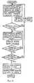
Блок управления 18 обеспечивает формирование и передачу данных в ЭВМ 3. Упрощенная блок-схема работы блока управления приведена на фиг.12. После включения питания блок управления 18 осуществляется самотестирование и проверку функционирования блока определения координат. При условии нормального завершения теста, блок управления 18 формирует команду запуска блока обработки сигналов с датчиков 20 и приводит проверку работы блока 20. В случае обнаружения ошибок блок управления 18 передает код ошибки на ЭВМ и переходит в режим ожидания команды на обработку ошибки. Если тест блока 20 прошел успешно, блок управления начинает выполнять рабочий цикл, в котором:
осуществляется определение координат указателя;
проводится проверка текущего режима работы. Текущий режим работы определяется формат информационной посылки в ЭВМ 3 и позволяет блокировать передачу данных, управляющих параметрами графического образца, для обеспечения совместимости устройства с программными продуктами не использующими эти данные. Управление режимом работы осуществляет ЭВМ 3, передавая блоку 20 специальные команды установки или сбросы режима блокировки;
осуществляется считывание из ячеек внутренней памяти блока 20 текущих значений данных для управления параметрами графического образа и состояние механического переключателя;
формируется информационная посылка, в соответствии с принятым протоколом обмена с ЭВМ 3;
осуществляется передача данных информационной посылки в ЭВМ 3;
проводится обработка принятых от ЭВМ 3 команд управления;
Переданные в ЭВМ 3 данные используются для формирования на экране устройства отображения графических объектов.The
the coordinates of the pointer are determined;
checking the current mode of operation. The current operating mode is determined by the format of the information package in the
reading from the cells of the internal memory of the
the information package is formed, in accordance with the accepted protocol of exchange with
the data of the information package is transmitted to the
processing of 3 control commands received from a computer is carried out;
The data transmitted to the
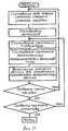
В качестве примера реализации возможностей предлагаемого устройства рассматривается алгоритм построения линии переменной толщины цвета и фактуры, блок-схема которого приведена на фиг.16. As an example of the implementation of the capabilities of the proposed device is considered an algorithm for constructing a line of variable color thickness and texture, a block diagram of which is shown in Fig.16.
В данном примере вначале определяется значение признака продолжения линии, затем осуществляется выбор текущего положения указателя в качестве начальной точки линии и определение начальной толщины линии как функции силы надавливания на указатель. На следующем шаге осуществляется выбор текущего положения указателя в качестве конечной точки линии и определение направления линии. Затем в начальной и конечной точках осуществляется построение к направлению линии перпендикуляров, длина которых пропорциональна толщине линии в этих точках. Одновременно осуществляется определение цвета и фактуры линии как функции силы давления на указатель. In this example, the value of the sign of continuation of the line is first determined, then the current position of the pointer is selected as the starting point of the line and the initial thickness of the line is determined as a function of the pressure force on the pointer. In the next step, the current position of the pointer as the endpoint of the line is selected and the direction of the line is determined. Then, at the start and end points, construction is carried out to the direction of the line of perpendiculars, the length of which is proportional to the thickness of the line at these points. At the same time, the color and texture of the line are determined as a function of the pressure force on the pointer.
При этом между дискретными значениями силы и номерами, определяющими цвет и фактуру линии,устанавливается однозначное соответствие. По имеющейся информации программа осуществляется закраску четырехугольника с вершинами на концах перпендикуляров текущим цветом и фактурой. При рисовании следующего элемента линии операции повторяются. In this case, a unique correspondence is established between the discrete values of the force and the numbers that determine the color and texture of the line. According to the available information, the program is filled in the quadrangle with the vertices at the ends of the perpendiculars with the current color and texture. When drawing the next line element, the operations are repeated.
На фиг.17 показано схематическое изображение элементов линии переменной толщины и схема сопряжения двух соседних элементов; на фиг.18 схематическое изображение элементов линии переменного толщины и переменной фактуры. On Fig shows a schematic representation of the elements of the line of variable thickness and a pairing circuit of two adjacent elements; on Fig schematic representation of the line elements of variable thickness and variable texture.
Примеры результатов работы графического устройства показаны на фиг.19 и 20, на которых изображены пейзаж и буквы алфавита. Examples of the results of the graphics device are shown in FIGS. 19 and 20, which depict the landscape and letters of the alphabet.
Устройства могут быть эффективно использованы при создании картин, кинофильмов, рекламы, в учебных процессах, цветомузыке, шоу-бизнесе, при выполнении проектных работ и создании игровых программ. Косвенное использование устройств возможно в медицине, технике, архитектуре, банковском деле, криминалистике. Devices can be effectively used when creating pictures, movies, advertising, in educational processes, color music, show business, when performing design work and creating game programs. Indirect use of devices is possible in medicine, engineering, architecture, banking, and forensics.
Claims (8)
Translated fromRussianPriority Applications (1)
| Application Number | Priority Date | Filing Date | Title |
|---|---|---|---|
| RU93021011ARU2067775C1 (en) | 1993-05-28 | 1993-05-28 | Device for reading pictures of objects |
Applications Claiming Priority (1)
| Application Number | Priority Date | Filing Date | Title |
|---|---|---|---|
| RU93021011ARU2067775C1 (en) | 1993-05-28 | 1993-05-28 | Device for reading pictures of objects |
Publications (2)
| Publication Number | Publication Date |
|---|---|
| RU2067775C1true RU2067775C1 (en) | 1996-10-10 |
| RU93021011A RU93021011A (en) | 1996-12-10 |
Family
ID=20140747
Family Applications (1)
| Application Number | Title | Priority Date | Filing Date |
|---|---|---|---|
| RU93021011ARU2067775C1 (en) | 1993-05-28 | 1993-05-28 | Device for reading pictures of objects |
Country Status (1)
| Country | Link |
|---|---|
| RU (1) | RU2067775C1 (en) |
Cited By (16)
| Publication number | Priority date | Publication date | Assignee | Title |
|---|---|---|---|---|
| RU2166203C1 (en)* | 2000-02-01 | 2001-04-27 | Супрун Антон Евгеньевич | Computer data input device |
| RU2168201C1 (en)* | 1999-11-03 | 2001-05-27 | Супрун Антон Евгеньевич | Computer data input device |
| RU2173882C1 (en)* | 2000-03-13 | 2001-09-20 | Супрун Антон Евгеньевич | Method for entering information in computer |
| RU2198428C2 (en)* | 1996-11-01 | 2003-02-10 | К Текнолоджиз Аб | Pen and process of recording |
| RU2236036C2 (en)* | 1997-01-29 | 2004-09-10 | Ко-Оперрайт Лимитед | Device for inputting symbols and commands into computer |
| RU2344483C2 (en)* | 2002-09-30 | 2009-01-20 | АйДжиТи | 3-dimensional text in game machine |
| RU2392656C2 (en)* | 2004-01-07 | 2010-06-20 | Майкрософт Корпорейшн | Universal computer device |
| US7901289B2 (en) | 2001-08-09 | 2011-03-08 | Igt | Transparent objects on a gaming machine |
| US7909696B2 (en) | 2001-08-09 | 2011-03-22 | Igt | Game interaction in 3-D gaming environments |
| US7918730B2 (en) | 2002-06-27 | 2011-04-05 | Igt | Trajectory-based 3-D games of chance for video gaming machines |
| US7934994B2 (en) | 2001-08-09 | 2011-05-03 | Igt | Virtual cameras and 3-D gaming environments in a gaming machine |
| US8002623B2 (en) | 2001-08-09 | 2011-08-23 | Igt | Methods and devices for displaying multiple game elements |
| US8012019B2 (en) | 2001-08-09 | 2011-09-06 | Igt | 3-D text in a gaming machine |
| US8267767B2 (en) | 2001-08-09 | 2012-09-18 | Igt | 3-D reels and 3-D wheels in a gaming machine |
| US8384710B2 (en) | 2007-06-07 | 2013-02-26 | Igt | Displaying and using 3D graphics on multiple displays provided for gaming environments |
| RU2701488C2 (en)* | 2014-08-12 | 2019-09-26 | МАЙКРОСОФТ ТЕКНОЛОДЖИ ЛАЙСЕНСИНГ, ЭлЭлСи | Stylus with colour control |
- 1993
- 1993-05-28RURU93021011Apatent/RU2067775C1/enactive
Non-Patent Citations (1)
| Title |
|---|
| Патент ЕПВ N 0414565, кл. G 06 F 3/033, 1991. Патент ЕПВ N 0229677, кл. G 06 K 11/06, 1988. Патент США N 307667, кл. G 06 K 11/06, 1989.* |
Cited By (27)
| Publication number | Priority date | Publication date | Assignee | Title |
|---|---|---|---|---|
| RU2198428C2 (en)* | 1996-11-01 | 2003-02-10 | К Текнолоджиз Аб | Pen and process of recording |
| RU2236036C2 (en)* | 1997-01-29 | 2004-09-10 | Ко-Оперрайт Лимитед | Device for inputting symbols and commands into computer |
| RU2168201C1 (en)* | 1999-11-03 | 2001-05-27 | Супрун Антон Евгеньевич | Computer data input device |
| RU2166203C1 (en)* | 2000-02-01 | 2001-04-27 | Супрун Антон Евгеньевич | Computer data input device |
| RU2173882C1 (en)* | 2000-03-13 | 2001-09-20 | Супрун Антон Евгеньевич | Method for entering information in computer |
| US9135774B2 (en) | 2001-08-09 | 2015-09-15 | Igt | 3-D reels and 3-D wheels in a gaming machine |
| US8267767B2 (en) | 2001-08-09 | 2012-09-18 | Igt | 3-D reels and 3-D wheels in a gaming machine |
| US9418504B2 (en) | 2001-08-09 | 2016-08-16 | Igt | 3-D reels and 3-D wheels in a gaming machine |
| US7901289B2 (en) | 2001-08-09 | 2011-03-08 | Igt | Transparent objects on a gaming machine |
| US7909696B2 (en) | 2001-08-09 | 2011-03-22 | Igt | Game interaction in 3-D gaming environments |
| US8523672B2 (en) | 2001-08-09 | 2013-09-03 | Igt | 3-D reels and 3-D wheels in a gaming machine |
| US7934994B2 (en) | 2001-08-09 | 2011-05-03 | Igt | Virtual cameras and 3-D gaming environments in a gaming machine |
| US8002623B2 (en) | 2001-08-09 | 2011-08-23 | Igt | Methods and devices for displaying multiple game elements |
| US8012019B2 (en) | 2001-08-09 | 2011-09-06 | Igt | 3-D text in a gaming machine |
| US8523671B2 (en) | 2002-06-27 | 2013-09-03 | Igt | Trajectory-based 3-D games of chance for video gaming machines |
| US8500535B2 (en) | 2002-06-27 | 2013-08-06 | Igt | Trajectory-based 3-D games of chance for video gaming machines |
| US7918730B2 (en) | 2002-06-27 | 2011-04-05 | Igt | Trajectory-based 3-D games of chance for video gaming machines |
| US8550893B2 (en) | 2002-06-27 | 2013-10-08 | Igt | Trajectory-based 3-D games of chance for video gaming machines |
| US8992320B2 (en) | 2002-06-27 | 2015-03-31 | Igt | Trajectory-based 3-D games of chance for video gaming machines |
| US9072967B2 (en) | 2002-06-27 | 2015-07-07 | Igt | Trajectory-based 3-D games of chance for video gaming machines |
| US9358453B2 (en) | 2002-06-27 | 2016-06-07 | Igt | Trajectory-based 3-D games of chance for video gaming machines |
| US9613496B2 (en) | 2002-06-27 | 2017-04-04 | Igt | Trajectory-based 3-D games of chance for video gaming machines |
| RU2344483C9 (en)* | 2002-09-30 | 2009-07-20 | АйДжиТи | 3-dimensional text in game machine |
| RU2344483C2 (en)* | 2002-09-30 | 2009-01-20 | АйДжиТи | 3-dimensional text in game machine |
| RU2392656C2 (en)* | 2004-01-07 | 2010-06-20 | Майкрософт Корпорейшн | Universal computer device |
| US8384710B2 (en) | 2007-06-07 | 2013-02-26 | Igt | Displaying and using 3D graphics on multiple displays provided for gaming environments |
| RU2701488C2 (en)* | 2014-08-12 | 2019-09-26 | МАЙКРОСОФТ ТЕКНОЛОДЖИ ЛАЙСЕНСИНГ, ЭлЭлСи | Stylus with colour control |
Similar Documents
| Publication | Publication Date | Title |
|---|---|---|
| RU2067775C1 (en) | Device for reading pictures of objects | |
| US4318096A (en) | Graphics pen for soft displays | |
| JP3895406B2 (en) | Data processing apparatus and data processing method | |
| US4961138A (en) | System and apparatus for providing three dimensions of input into a host processor | |
| US6172665B1 (en) | Mouse and trackball with optimal measurement optics | |
| JP3205585B2 (en) | Input terminal device | |
| JPH0329017A (en) | Mouse for data input | |
| JP3171866B2 (en) | Pattern input device | |
| US12229474B2 (en) | Position detection system that outputs artificial sound imitating sound that occurs when stationery is used | |
| US5751275A (en) | Two-- and three--dimensional trackball with coordinate transformations | |
| US5061828A (en) | Digitizer stylus with Z-axis side pressure control | |
| JP3327056B2 (en) | Pen-type input device | |
| US11644912B2 (en) | Interface device and on-panel pad | |
| AU613637B2 (en) | System and apparatus for providing three dimensions of input to a host processor | |
| JPH08152955A (en) | Three-dimensional coordinate position detector and three-dimensional coordinate position display device | |
| JP3708169B2 (en) | Pen-type input device | |
| JP2002091898A (en) | Coordinate information input device, coordinate information input method, and storage medium storing a program for inputting coordinate information | |
| JPH07200152A (en) | Tablet input electronics | |
| JPH01293477A (en) | Measuring instrument | |
| JP3027905B2 (en) | Operability evaluation device | |
| JPH03118628A (en) | Picture input device | |
| Capowski | Laboratory Computer Hardware | |
| JP2621808B2 (en) | Pen-type input device | |
| JPH11338634A (en) | Mouse input device | |
| JPH05158613A (en) | Mouse |