RU2063710C1 - Surgical suture appliance for endoscopic operations and agraffe - Google Patents
Surgical suture appliance for endoscopic operations and agraffeDownload PDFInfo
- Publication number
- RU2063710C1 RU2063710C1RU9494014586ARU94014586ARU2063710C1RU 2063710 C1RU2063710 C1RU 2063710C1RU 9494014586 ARU9494014586 ARU 9494014586ARU 94014586 ARU94014586 ARU 94014586ARU 2063710 C1RU2063710 C1RU 2063710C1
- Authority
- RU
- Russia
- Prior art keywords
- bracket
- agraffe
- grooves
- angle
- legs
- Prior art date
Links
- 0CC(CCC1)*1=CChemical compoundCC(CCC1)*1=C0.000description2
Images


Classifications
- A—HUMAN NECESSITIES
- A61—MEDICAL OR VETERINARY SCIENCE; HYGIENE
- A61B—DIAGNOSIS; SURGERY; IDENTIFICATION
- A61B17/00—Surgical instruments, devices or methods
- A61B17/068—Surgical staplers, e.g. containing multiple staples or clamps
- A61B17/072—Surgical staplers, e.g. containing multiple staples or clamps for applying a row of staples in a single action, e.g. the staples being applied simultaneously
- A61B17/07207—Surgical staplers, e.g. containing multiple staples or clamps for applying a row of staples in a single action, e.g. the staples being applied simultaneously the staples being applied sequentially
- A—HUMAN NECESSITIES
- A61—MEDICAL OR VETERINARY SCIENCE; HYGIENE
- A61B—DIAGNOSIS; SURGERY; IDENTIFICATION
- A61B17/00—Surgical instruments, devices or methods
- A61B17/064—Surgical staples, i.e. penetrating the tissue
- A61B17/0644—Surgical staples, i.e. penetrating the tissue penetrating the tissue, deformable to closed position
- A—HUMAN NECESSITIES
- A61—MEDICAL OR VETERINARY SCIENCE; HYGIENE
- A61B—DIAGNOSIS; SURGERY; IDENTIFICATION
- A61B17/00—Surgical instruments, devices or methods
- A61B17/068—Surgical staplers, e.g. containing multiple staples or clamps
- A61B17/072—Surgical staplers, e.g. containing multiple staples or clamps for applying a row of staples in a single action, e.g. the staples being applied simultaneously
- A61B2017/07214—Stapler heads
- A61B2017/07228—Arrangement of the staples
- A—HUMAN NECESSITIES
- A61—MEDICAL OR VETERINARY SCIENCE; HYGIENE
- A61B—DIAGNOSIS; SURGERY; IDENTIFICATION
- A61B17/00—Surgical instruments, devices or methods
- A61B17/068—Surgical staplers, e.g. containing multiple staples or clamps
- A61B17/072—Surgical staplers, e.g. containing multiple staples or clamps for applying a row of staples in a single action, e.g. the staples being applied simultaneously
- A61B2017/07214—Stapler heads
- A61B2017/07271—Stapler heads characterised by its cartridge
Landscapes
- Health & Medical Sciences (AREA)
- Life Sciences & Earth Sciences (AREA)
- Surgery (AREA)
- Heart & Thoracic Surgery (AREA)
- Engineering & Computer Science (AREA)
- Biomedical Technology (AREA)
- Nuclear Medicine, Radiotherapy & Molecular Imaging (AREA)
- Medical Informatics (AREA)
- Molecular Biology (AREA)
- Animal Behavior & Ethology (AREA)
- General Health & Medical Sciences (AREA)
- Public Health (AREA)
- Veterinary Medicine (AREA)
- Surgical Instruments (AREA)
Abstract
Description
Translated fromRussianИзобретение относится к медицинской технике и предназначено для наложения механического скобочного шва при эндоскопических операциях. The invention relates to medical equipment and is intended for the application of a mechanical staple suture during endoscopic operations.
Известен хирургический сшивающий аппарат, содержащий корытообразный скобочный корпус с рукояткой, два сменных магазина со скобочными пазами и расположенными в них толкателями, упорный корпус, связанную с ним посредством двух осей и замкнутых фигурных пазов подвижную упорную губку с матрицей для загиба скобок, корытообразный съемный ограничитель ткани, механизм для подачи толкателей с двумя пластинчатыми клиньями, соединенным с ними дисковым ножом для разрезания ткани и винтовым приводом, механизм смыкания скобочного и упорного корпусов с винтовым приводом [ 1]
Скобка, используемая в этом аппарате, имеет плоскую П-образную форму [2]
Однако известное устройство имеет большие габариты рабочей части, что ограничивает возможность его применения в условиях эндоскопичеcких операций и ограниченных размерах операционного поля.Known surgical stapler, containing a trough-shaped bracket body with a handle, two removable magazines with bracket grooves and pushers located therein, a thrust housing associated with it through two axes and closed curly grooves, a movable thrust sponge with a matrix for bending brackets, a trough-like removable fabric stop , a mechanism for feeding pushers with two plate wedges, a circular knife for cutting fabric and a screw drive connected to them, a mechanism for closing the bracket and thrust housing s screw drive [1]
The bracket used in this apparatus has a flat U-shape [2]
However, the known device has large dimensions of the working part, which limits the possibility of its use in endoscopic operations and the limited size of the surgical field.
Целью изобретения является уменьшение размеров рабочей части аппарата, расширение функциональных возможностей, упрощение конструкции шьющей части и повышение ее надежности. The aim of the invention is to reduce the size of the working part of the apparatus, expanding the functionality, simplifying the design of the sewing part and increasing its reliability.
Данная цель достигаются тем, что скобочные пазы выполнены в виде размещенных в скобочном корпусе парных желобков под скобочные ножки с прямыми или криволинейными поперечными сечениями, причем стенки желобков в поперечном сечении ориентированы к боковым поверхностям скобочного корпуса под прямым или тупым, или острым углом, клин-толкатель выполнен, как минимум, с одной рабочей боковой продольной канавкой под скобочные спинки, имеющей, как минимум, один наклонный участок, открытый на поверхности клина-толкателя, ориентированной к фигурным скобочным лункам, оси которых в плоскости матрицы образуют между содой угол, не равный 180o, еще тем, что желобки ориентированы к матрице под углом, равным или отличным от угла наклона наклонного участка продольной канавки на клине-толкателе, фигурные скобочные лунки в паре выполнены с неодинаковым продольным профилем, а упорный корпус соединен со скобочным корпусом с возможностью одновременного поперечного и продольного перемещения, причем один из соединительных пазов в скобочном корпусе, выполненый под закрепл нную на упорном корпусе ось, ориентирован к продольной оси аппарата под углом, равным углу наклона желобков к матрице, еще тем, что ножки скобки выполнены с одинаковыми изгибами, ориентированными к плоскости заостренных концов под прямым или острым, или тупым углом, а спинка ориентирована к концам под прямым или косым углом и выполнена в виде перемычки с прямой или криволинейной продольной осью, при этом изогнутые участки ножек ориентированы параллельно или под углом друг к другу и выполнены прямыми или криволинейными.This goal is achieved by the fact that the bracket grooves are made in the form of paired grooves located in the bracket body for bracket legs with straight or curved cross sections, and the walls of the grooves in the cross section are oriented to the side surfaces of the bracket body at a straight or obtuse or acute angle, the wedge the pusher is made with at least one working lateral longitudinal groove under the bracket backs, having at least one inclined section open on the surface of the pusher-wedge oriented to the curly m bracket holes, the axes of which in the plane of the matrix form an angle between the soda, not equal to 180o , moreover, the grooves are oriented to the matrix at an angle equal to or different from the angle of inclination of the inclined section of the longitudinal groove on the pushing wedge, curly bracket holes in pair made with an unequal longitudinal profile, and the thrust housing is connected to the bracket body with the possibility of simultaneous lateral and longitudinal movement, moreover, one of the connecting grooves in the bracket housing, made under the fixed on the thrust housing the axis is oriented to the longitudinal axis of the apparatus at an angle equal to the angle of inclination of the grooves to the matrix, moreover, that the legs of the bracket are made with the same bends, oriented to the plane of the pointed ends at a right or acute, or obtuse angle, and the back is oriented to the ends at a straight or oblique angle and made in the form of a jumper with a straight or curved longitudinal axis, while the curved sections of the legs are oriented parallel or at an angle to each other and are made straight or curved.
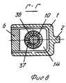
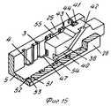
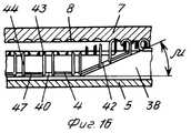
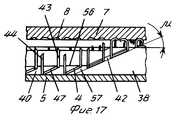
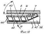
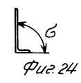
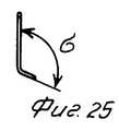
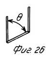
На фиг. 1 изображен хирургический сшивающий аппарат для эндоскопических операций в закрытом состоянии с клином-толкателем, перемещающимся в тело аппарата, вид сбоку; на фиг.2- рабочая часть аппарата с косым расположением скобочных пазов и паза для оси упорного корпуса в закрытом состоянии; на фиг. 3- аппарат, вид сверху; на фиг.4- аппарат в открытом состоянии с клином-толкателем, перемещающимся вперед, вид сбоку; на фиг.5 сечение А-А на фиг. 1; на фиг.6- сечение Б-Б на фиг.1; на фиг.7- сечение В-В на фиг.1; на фиг. 8- сечение Г-Г на фиг.1; на фиг.9- вид Д на фиг.1; на фиг.10- вид Е на фиг. 1; на фиг.11- вид Ж на фиг.4; на фиг.12- сечение И-И на фиг.10; на фиг. 13- скобка в скобочных пазах с задней стенкой арочной формы вид сверху; на фиг. 14- схема удержания скобок в прямых пазах; на фиг.15- схема удержания скобок в косых пазах; на фиг.16- схема деформации прямых скобок; на фиг.17- схема деформации косых скобок; на фиг.18- схема выталкивания скобок клином-толкателем с несколькими продольными и наклонными пазами; на фиг.19- схема деформации скобок в наклонных скобочных пазах; на фиг.20- скобка с отогнутой спинкой; на фиг.21- деформированная скобка, вид в плане; на фиг. 22- деформированная скобка, вид сверху; на фиг.23- скобка, вид в плане; на фиг.24- скобка с ножками, изогнутыми под прямым углом, вид сбоку; на фиг.25- скобка с ножками, изогнутыми под углом, отличным от прямого, вид сбоку; на фиг. 26- скобка косая уступом вправо, вид в плане; на фиг.27- скобка косая уступом влево, вид в плане; на фиг.28- скобка в прямых скобочных пазах с криволинейной спинкой, вид сверху; на фиг.29- скобка трапецеидальной формы в косых скобочных пазах, длина спинки меньше расстояния между ножками, вид сверху; на фиг. 30- скобка трапецеидальной формы в косых скобочных пазах, длина спинки больше расстояния между ножками, вид сверху; на фиг.31- скобка с фасонными отогнутыми участками ножек, вид сверху; на фиг.32- расположение скобок в ткани, вид снизу; на фиг.33- схема перемещения фигурных лунок для загиба скобок при выборе зазора прошивания при наклонном расположении скобочных пазов в скобочном корпусе. In FIG. 1 shows a side view of a surgical stapler for closed endoscopic operations with a pusher wedge moving into the body of the apparatus; figure 2 - the working part of the apparatus with an oblique arrangement of the bracket grooves and the groove for the axis of the thrust housing in the closed state; in FIG. 3- apparatus, top view; figure 4 - apparatus in the open state with a wedge-pusher moving forward, side view; in Fig. 5, section AA in fig. 1; Fig.6 is a section bB in Fig.1; figure 7 - section bb in figure 1; in FIG. 8- section GG in figure 1; Fig.9 is a view of D in Fig.1; 10; view E in FIG. 1; figure 11 is a view W in figure 4; in Fig.12 - section II in Fig.10; in FIG. 13- bracket in parentheses with a back wall of an arched form; top view; in FIG. 14 is a diagram of holding brackets in straight grooves; on Fig - diagram of holding brackets in oblique grooves; on Fig - diagram of the deformation of the parentheses; on Fig - diagram of the deformation of oblique brackets; on Fig - scheme of pushing the brackets with a wedge-pusher with several longitudinal and inclined grooves; on Fig - diagram of the deformation of the brackets in the inclined bracket grooves; Fig.20 is a bracket with a bent back; on Fig - deformed bracket, view in plan; in FIG. 22 - deformed bracket, top view; Fig.23 is a bracket, a view in plan; Fig.24 is a bracket with legs bent at right angles, side view; on Fig - bracket with legs bent at an angle different from the straight side view; in FIG. 26- bracket oblique ledge to the right, plan view; in Fig.27 - brace oblique ledge to the left, view in plan; on Fig - bracket in straight bracket grooves with a curved back, top view; on Fig-trapezoidal bracket in oblique bracket grooves, the length of the back is less than the distance between the legs, top view; in FIG. 30- trapezoidal bracket in oblique bracket grooves, back length longer than the distance between the legs, top view; on Fig - bracket with shaped bent sections of the legs, top view; on Fig - the location of the brackets in the fabric, bottom view; in Fig.33 is a diagram of the movement of curly holes for bending brackets when choosing a stitching gap with an inclined arrangement of bracket grooves in the bracket body.
Аппарат содержит корытообразный скобочный корпус 1 с укрепленной на нем рукояткой 2, желобками 3 для ножек скобок 4 в рабочей части 5 скобочного корпуса 1, упорный корпус 6 с матрицей 7, на которой расположены фигурные лунки 8 для загиба скобок 4, ограничитель ткани 9, винтовой привод 10 для сведения рабочих шьющих частей (скобочного корпуса 1 и упорного корпуса 6), винтовой привод 11 для наложения скобок 4. The apparatus contains a trough-
Винтовой привод 10 для сведения рабочих шьющих частей выполнен в виде винта с накатанной цилиндрической головкой 12 и круговой проточкой 13, соединенного резьбой с упорным корпусом 6, на конце которого для этого выполнена гайка 14. The
Скобочный корпус 1 имеет корытообразную форму. На боковых стенках 15 и 16 скобочного корпуса 1 выполнены продольные пазы 17 и 18 в передней части, два таких же паза 19 в задней части и поперечные пазы 20 и 21 с боковыми стенками 22 и 23. В хвостовой части корпуса 1 выполнена выточка 24 для зацепления с круговой проточкой 13 винта 10. Bracket
Рабочая часть 5 скобочного корпуса 1 имеет боковые стенки 25 и 26, в которых выполнены желобки 3. The working
Упорный корпус 6 выполнен составным с подвижной упорной губкой 27, на боковых поверхностях которой имеются оси 28 и 29, установленные в замкнутых фигурных пазах 30 и 31, расположенных в передней вилкообразной части 32 упорного корпуса 6, а ось 28, в свою очередь, располагается еще и в поперечных пазах 20 и 21 скобочного корпуса 1. The
Хвостовая часть подвижной упорной губки 27 входит в вилкообразную часть 32 упорного корпуса 6. Упорный корпус 6 имеет с двух сторон выступы 33 и 34 в передней части и два выступа 35 в задней, которые входят в продольные пазы 17, 18 и 19 на боковых стенках 15 и 16 скобочного корпуса 1. Хвостовая часть скобочного корпуса 6 с помощью закрепленной на ней гайки 14 соединена с винтом 10. The tail portion of the
Винтовой привод 11 для наложения скобок 4 состоит из резьбового стержня 36, соединенного с внутренней резьбой гайки-барашка 37, которая находится в зацеплении с винтом 10 с возможностью вращения без возможности осевого перемещения. На стержне 36 укреплен клин-толкатель 38, имеющий в нижней части продольные канавки 39 и 40, параллельные направлению движения клина-толкателя 38 и наклонные канавки 41 и 42 для выталкивания скобок 4, заканчивающиеся на поверхности клина-толкателя 38, ориентированной к лункам 8 матрицы 7. The
Скобка 4 имеет две заостренные параллельные ножки 43 и 44, имеющие в своей нижней части отогнутые в бок участки 45 и 46 на угол σ, равный или отличный от 90o (фиг.24, 25) таким образом, что спинка 47 между ножками 43 и 44 скобки 4 находится вне плоскости, в которой располагаются ножки.The
Аппарат работает следующим образом. The device operates as follows.
Цилиндрическую накатанную часть 12 винта 10 вращают против часовой стрелки до упора, при этом оси 28 и 29, скользя по фигурным пазам 30 и 31, заставляют подвижную губку 27 поворачиваться относительно оси 28, находящейся в пазу 20 скобочного корпуса 1. The cylindrical
Губка 27 отходит от рабочей части 5 скобочного корпуса 1, освобождая гнездо 46. Аппарат раскрыт. Скобочные пазы заряжаются скобками 4. Аппарат, изображенный на фиг.1 и 2, имеющий клин-толкатель 38, занимающий в исходном положении все пространство между боковыми стенками 25 и 26 на всей длине шва с целью удержания скобок, заряжается ими последовательно с продвижением клина-толкателя 38 в тело аппарата с нижней стороны рабочей части 5 скобочного корпуса 1. Для этого в скобочном корпусе 1 имеется окно 49, а в клине-толкателе выемка 50. Аппарат, изображенный на фиг. 4, заряжается скобками 4 со стороны матрицы 7. The
На операции аппарат вводят в узкую глубокую рану в закрытом виде. Подойдя к оперируемому органу, аппарат раскрывают так, как было описано выше. Ушиваемый орган располагают в гнезде 48 между рабочей частью 5 скобочного корпуса 1 и упорной губкой 27. Цилиндрическую накатанную часть 12 винта 10 вращают по часовой стрелке. При этом круговая проточка 13 винта 10 вращается в выточке 24 скобочного корпуса 1, не давая сместиться винту 10 вдоль оси аппарата. С помощью гайки 14 упорным корпус 6 перемещается вперед. Ось 28 упорной губки 27, находящаяся в фигурном пазу 30 упорного корпуса 6 и в поперечном пазу 20 скобочного корпуса 1, не дающем ей смещаться вдоль оси аппарата и ось 29 упорной губки 27, находящаяся в фигурном пазу 31 упорного корпуса 6, скользят в этих фигурных пазах при перемещении упорного корпуса 6 вперед и заставляют подвижную упорную губку 27 опускаться относительно скобочного корпуса 1 и сближаться матрицу 7 с рабочей частью 5 скобочного корпуса 1. При этом выступы 33, 34 и два выступа 35 упорного корпуса 6 скользят в пазах 17, 18 и 19 скобочного корпуса 1 и соединяют упорный 6 и скобочный 1 корпуса. Ткань сжимается поверхностями матрицы 7 и рабочей части 5 скобочного корпуса 1 до зазора прошивания зазора, на котором происходит загиб ножек скобки 4 в O-образную или В-образную форму. Вращая гайку-барашек 37 по часовой стрелке, клин-толкатель 38 винтового привода 11 для наложения скобок 4 подается назад в аппарате, изображенном на фиг.1 и 2, и вперед в аппарате, изображенном на фиг. 4. Наклонные канавки 41 и 42 клина-толкателя 38 скользят по спинкам 47 скобок 4, выталкивая скобки 4 в сторону матрицы 7 с лунками 8. During operations, the device is inserted into a narrow deep wound in a closed form. Approaching the operated organ, the apparatus is opened as described above. The sutured body is located in the
Ножки 43 и 44 скобок 4 прокалывают ткань и упираются в лунки 8. лунки в каждой паре для каждой скобки располагаются под некоторые углом b (фиг.9) к плоскости, в которой лежат ножки 43 и 44 скобки 4, совпадающей с направлением шва, и образуют между собой тупой угол g. Такое расположение лунок 6 на матрице 7 позволяет загибаться ножкам 43 и 44, при воздействии клина- толкателя 38, под углом g друг к другу (фиг.22) в В-образную форму (фиг.21), при этом концы ножек 43 и 44 будут направлены в спинку 47. В этом случае шов получается достаточной герметичности. Тем не менее возможно применение известных матриц, в которых угол между направлениями лунок в каждой паре для каждой скобки равен 180o.The
Описываемый в данном случае аппарат накладывает один двухрядный скобочный шов (фиг.32) со скобками, смещенными в одном ряду относительно другого на полшага. По своим параметрам шов соответствует известному скобочному шву, состоящему из П-образных металлических скобок. The apparatus described in this case imposes one two-row bracket stitch (Fig. 32) with brackets shifted in one row relative to the other by half a step. According to its parameters, the seam corresponds to the well-known stitch seam consisting of U-shaped metal brackets.
Возможность передачи поступательного движения от клина-толкателя 38, перемещающегося вдоль расположения рядов скобок 4, непосредственно на скобки 4 осуществляется за счет того, что скобка 4 имеет спинку 47, лежащую вне плоскости ножек 43 и 44. Ножки 43 и 44 скобки 4 располагаются в желобках 3 (фиг.14 и 15), выполненных в боковых стенках 15 и 16 рабочей части 5 скобочного корпуса 1, с внутренних их сторон. При этом спинки 47 скобок 4 размещаются в пространстве между боковыми стенками 25 и 26 рабочей части 5 скобочного корпуса 1 за счет того, что они (спинки) "вынесены" из плоскости ножек 43 и 44 скобок 4 отогнутыми участками 45 и 46 этих ножек. The ability to transmit translational motion from the wedge-
Клин-толкатель 38 перемещается в пространстве между боковыми стенками 25 и 26 рабочей части 5 скобочного корпуса 1 вдоль расположения рядов скобок 4. Своими наклонными канавками 41 и 42 на своих боковых поверхностях (по одной для каждого ряда скобок) он воздействует на спинки 47 скобок 4 и выталкивает их в сторону матрицы 7. Так как ножки 43 и 44 скобок 4 расположены в скобочных пазах 3, направленных в сторону матрицы 7, то скобки 4 перемещаются только в направлении матрицы 7. The wedge-
Желобки 3 в своем поперечном сечении могут иметь прямые боковые 51 и 52 и заднюю 53 стенки. Боковые 51 и 52 стенки перпендикулярны внутренним поверхностям стенок 25 и 26 рабочей части 5 скобочного корпуса 1 (вариант аппарата фиг. 1 и 2 и схема фиг.14), задняя стенка 53 выполняется прямой или криволинейной (арочной) формы (фиг.13). Скобка имеет отогнутые участки 45 и 46 ножек 43 и 44, перпендикулярные спинке 47, угол w на фиг.13. Такая скобка может вываливаться из таких скобочных пазов в пространство между боковыми стенками 25 и 26 рабочей части 5 скобочного корпуса 1. Для предотвращения этого клин-толкатель 38 в исходном положении занимает пространство между боковыми стенками 25 и 26 рабочей части 5 скобочного корпуса 1 по всей длине расположения скобок 4 в желобках 3. Он своими боковыми стенками закрывает все желобки 3 и удерживает в них ножки 43 и 44 скобок 4. В нижней части клина-толкателя 38 выполнены продольные канавки 39 и 40, параллельные направлению его движения. В этих канавках размещаются спинки 47 скобок 4. Наклонные канавки 41 и 42 для выталкивания скобок 4 клина-толкателя 38 находятся вне расположения скобок. При прошивании клин-толкатель 38 перемещается вдоль рядов скобок и нижние продольные канавки 39 и 40 продвигаются вдоль спинок 47 скобок 4, переходя в наклонные канавки 41 и 42, которые выталкивают скобки 4. The
Такой клин-толкатель, удерживающий скобки в скобочных пазах еще до прошивания, имеет большую длину. Он может выдвигаться вперед из тела аппарата, что резко увеличивает габариты аппарата (необходимо пространство в передней части для размещения клина-толкателя), или втягиваться в аппарат, как на фиг.1 и 2. Such a wedge-pusher holding the brackets in the bracket grooves even before flashing, has a large length. It can be moved forward from the body of the apparatus, which dramatically increases the dimensions of the apparatus (you need space in the front part to accommodate the pusher wedge), or be pulled into the apparatus, as in Figs. 1 and 2.
Для уменьшения длины клина-толкателя скобки должны без его помощи удерживаться в скобочных пазах. Для этого боковые стенки 51 и 52 желобков 3 в боковых стенках 25 и 26 рабочей части 5 скобочного корпуса 1 могут быть выполнены в поперечном сечении прямой формы но под углом v, не равным 90o, к внутренним поверхностям боковых стенок 25 и 26 рабочей части 5 скобочного корпуса 1 или криволинейной формы (фиг.29, 30, 31). Скобки 4 соответственно должны иметь ответную форму отогнутых участков 45 и 46 ножек 43 и 44. Эти участки могут иметь прямую форму и образовывать со спинкой 47 угол v отличный от 90o, и (или) криволинейную форму. Спинки 47 могут быть такой же длины, как расстояние между ножками 43 и 44 скобки 4, или большей длины, или меньшей.To reduce the length of the pusher wedge, the brackets should be held in the bracket slots without it. For this, the
Такая конструкция скобки позволяет ей удерживаться в желобках 3 рабочей части скобочного корпуса своими ножками без помощи клина-толкателя. Клин-толкатель 38 в конструкции аппарата, изображенной на фиг.4, 11 и 15, имеет длину нижней продольной канавки 39 или 40 такую, которая позволяет захватить спинку 47 одной скобки 4 при его продвижении и перевести ее в наклонную канавку 41 или 42. В начале нижних продольных канавок 39 и 40 могут иметься клинообразные расширения 54 для направления спинок 47 скобок 4 в эти продольные канавки по мере продвижения клина-толкателя 38 вдоль рядов скобок 4. This design of the bracket allows it to be held in the
Клин-толкатель 38 для уменьшения площади соприкосновения с ушиваемой тканью может иметь обнижение 55 высоты в его передней части перед выходом наклонных канавок 41 и 42 на верхнюю его поверхность. The wedge-
Нижние продольные канавки 39 и 40 клина-толкателя 38 могут иметь "замкнутую" форму, то есть канавки имеют верхнюю 56, боковую 57 и нижнюю 58 поверхности (фиг.14), или"открытую" форму, то есть канавки имеют верхнюю 56 и боковую 57 поверхности (фиг.17). При "открытой" форме продольных канавок клин-толкатель имеет высоту меньше, чем при "закрытой" форме, так как в этом случае его высота может быть равной высоте скобки, в то время как в случае продольных канавок "закрытой" формы клин-толкатель обязательно имеет высоту больше, чем высота скобок. The lower
Скобка 4 может иметь прямую форму, то есть когда между спинкой 47 и ножками 43 и 44 в плане имеется угол h=90o°(фиг.23).The
Во время прошивания при прохождении спинок 47 прямых скобок 4 по наклонным канавкам 41 и 42 клина-толкателя 38 происходит изменение угловых m положений спинки 47 и ножек 43 и 44, так как ножки сохраняют свое первоначальное направление, а перемычка отклоняется на угол m наклона канавок 41 и 42 от своего первоначального положения. Так как расстояние между ножками 43 и 44 скобки 4 (фиг.16) остается неизменным, то при деформации прямой скобки 4 увеличивается длина спинки 47. Чем больше угол наклона наклонных канавок 41 и 42, тем больше удлинение спинки 47. Для компенсации этих удлинений спинки 47 скобки 4 эта спинки может быть выполнена криволинейной (например арочной) формы (фиг. 28). Увеличение длины спинки 47 становится возможным за счет ее выпрямления. During flashing, when the
В прямых скобках при переходе перемычек 47 между ножками из нижних продольных канавок 39 и 40 клина толкателя 38 в наклонные канавки 41 и 42 (фиг. 16) скобки 4 деформируются так, как было описано выше. Отогнутые участки 45 и 46 ножек 43 и 44 подвергаются скручиванию и возникают усилия, препятствующие выталкиванию скобок. Для устранения этого фактора нижние продольные канавки 39 и 40 в клине-толкателе 38 могут быть несколько расширены, а скобки 4 выполнены таким образом, что угол в плане между спинкой 47 и ножками 43 и 44 совпадает с углом m наклона наклонной канавки 41 и 42 (фиг.17) при сохранении параллельности ножек 43 и 44. В этом случае при выталкивании скобок 4 исключается скручивание отогнутых участков 45 и 46 ножек 43 и 44 скобки 4. Такой вид скобок имеет два типа: правый (уступом вправо)(фиг.26) и левый (уступом влево)(фиг.27) в зависимости от того, с какой стороны от клина-толкателя 38 они располагаются по направлению его перемещения. При такой конструкции скобок их высота, при той же высоте ножек 43 и 44 как и в прямых скобках, неcкoлько увеличивается (фиг.23). In straight brackets, when the
В описанных выше косых скобках угол q наклона спинки 47 по отношению к ножкам 43 и 43 может не совпадать с углом m наклона наклонных канавок 41 и 42 клина-толкателя 38. Если этот угол q cделать меньше угла m наклона наклонных канавок 41 и 42, то скручивание отогнутых участков 45 и 46 ножек скобки и удлинение спинки 47 сохраняются, но становятся меньше, чем в случае с прямой скобкой. Вместе с этим высота такой косой скобки меньше высоты скобки, в которой угол q наклона слинял 47 равен углу m наклона наклонных канавок 41 и 42 (вариант описан выше). In the oblique brackets described above, the inclination angle q of the
Для уменьшения длины участка для выталкивания скобок на клине-толкателе 38 угол наклона m наклонных канавок 41 и 42 может быть несколько увеличен. В этом случае может возникнуть опасность срезания отогнутых участков 45 и 46 ножек 43 и 44 скобок 4 при их выталкивании. To reduce the length of the area for pushing the brackets on the
Для устранения этой опасности желобки 3 в рабочей части 5 скобочного корпуса 1 могут быть выполнены под углом a к поверхности матрицы, установленной на зазоре прошивания, равным или отличным от угла m таким образом, что желобки 3 и ножки 43 и 44 скобок 4 составляют с наклонными канавками 41 и 42 клина-толкателя 38 прямой или другой угол (фиг.2, 19 и 33). В этом случае устраняется возможность срезания отогнутых участков 45 и 46 ножек 43 и 44 скобки 4 и за счет наклонного расположения ножек 43 и 44 уменьшается высота скобки 4 по вертикали и, следовательно, рабочей части 5 скобочного корпуса 1. В наклонных желобках 3 можно размещать как косые так и прямые скобки 4. Соответственно спинки 47 между ножками этих скобок располагаются или параллельно оси аппарата (скобка приобретает косую форму), или под некоторые углом к оси аппарата, равным или отличным от угла наклона наклонных канавок 41 и 42 клина-толкателя 38 (соответственно скобка приобретает прямую или тоже косую форму). To eliminate this danger, the
Лунки 8 матрицы 7 для загиба ножек 43 и 44 скобки 4 должны быть при изменении зазора прошивания зазора между матрицей 7 и рабочей частью 5 скобочного корпуса 1 всегда напротив заточенных участков ножек 43 и 44 скобки 4. Для этого стенки 21 и 22 поперечного паза 20 скобочного корпуса 1 выполнены под тем же углом j, равным углу a наклона желобков 3 в рабочей части 5 скобочного корпуса 1 (фиг.2 и 33). Это позволяет перемещаться упорной губке 27 с матрицей 7 не в вертикальном направлении "ж" при изменении зазора прошивания, например от "б" до "а", а в направлении "г", состоящем из вертикального перемещения "д" и горизонтального "е". Это направление совпадает с направлением ножек 43 и 44 скобки 4 при ее выталкивании. В этом случае ножки скобки на любом зазоре прошивания будут направлены в лунки 8 матрицы 7. Профили лунок 8 в продольном их сечении в каждой паре для каждой скобки неодинаковы. Каждая из пары имеет такую форму, что ножки скобки при контакте с поверхностью лунки испытывают равные или почти равные усилия деформации для каждой ножки. The
Для уменьшения хода клина-толкателя 38 на его каждой боковой поверхности выполняется несколько наклонных 41 и 42 и нижних продольных 39 и 40 канавок (фиг.18). В этом случае с каждой стороны клина-толкателя выталкивается сразу несколько скобок 4 и клин-толкатель 38 совершает меньшее перемещение, чем при выталкивании ряда скобок одной наклонной канавкой. To reduce the stroke of the
Аппарат позволяет накладывать на органы один двухрядный шов. Возможно исполнение аппарата для наложения одного, трех и более рядов скобок с возможностью рассечения ткани между ними клиновым или циркулярным ножом, связанным с клиньями-толкателями. The device allows you to impose one double-row suture on the organs. It is possible to design an apparatus for applying one, three or more rows of brackets with the possibility of dissecting the tissue between them with a wedge or circular knife connected with pusher wedges.
Нижние продольные канавки 39 и 40 клина-толкателя 38 могут соединяться с наклонными канавками 41 и 42 непосредственно напрямую, переходя одни в другие, могут соединяться при помощи криволинейного участка, когда верхние 56 и нижние 58 их поверхности выполнены в зоне соединения канавок криволинейной (например радиусной) формы, могут соединяться ножними поверхностями 58 непосредственно напрямую, а верхними поверхностями 56 при помощи переходного участка криволинейной ( например, радиусной) формы. The lower
Описанные конструкции и варианты исполнения элементов конструкции аппарата и скобки позволяют существенно уменьшить габариты рабочей части аппарата и упростить конструкцию. Конструкция аппарата обеспечивает проход к ушиваемому органу и тканям через троакары и узкие, глубокие раны. Аппарат обеспечивает герметичность и гемостатичность шва при ушивании полых органов. ЫЫЫ2 ЫЫЫ4 ЫЫЫ6 ЫЫЫ8 ЫЫЫ10 ЫЫЫ12 ЫЫЫ14 ЫЫЫ16 ЫЫЫ18 ЫЫЫ20 ЫЫЫ22 ЫЫЫ24 ЫЫЫ26 ЫЫЫ28 ЫЫЫ30 ЫЫЫ32 The described structures and embodiments of the structural elements of the apparatus and brackets can significantly reduce the dimensions of the working part of the apparatus and simplify the design. The design of the device provides access to the sutured organ and tissues through trocars and narrow, deep wounds. The device provides tightness and hemostatic seam when suturing hollow organs. YYY2 YYY4 YYY6 YYY8 YYY10 YYY12 YYY14 YYY16 YYY18 YYY20 YYY22 YYY24 YYY26 YYY28 YYY30 YYY32
Claims (3)
Translated fromRussianPriority Applications (1)
| Application Number | Priority Date | Filing Date | Title |
|---|---|---|---|
| RU9494014586ARU2063710C1 (en) | 1994-04-19 | 1994-04-19 | Surgical suture appliance for endoscopic operations and agraffe |
Applications Claiming Priority (1)
| Application Number | Priority Date | Filing Date | Title |
|---|---|---|---|
| RU9494014586ARU2063710C1 (en) | 1994-04-19 | 1994-04-19 | Surgical suture appliance for endoscopic operations and agraffe |
Publications (2)
| Publication Number | Publication Date |
|---|---|
| RU2063710C1true RU2063710C1 (en) | 1996-07-20 |
| RU94014586A RU94014586A (en) | 1996-11-20 |
Family
ID=20154985
Family Applications (1)
| Application Number | Title | Priority Date | Filing Date |
|---|---|---|---|
| RU9494014586ARU2063710C1 (en) | 1994-04-19 | 1994-04-19 | Surgical suture appliance for endoscopic operations and agraffe |
Country Status (1)
| Country | Link |
|---|---|
| RU (1) | RU2063710C1 (en) |
Cited By (21)
| Publication number | Priority date | Publication date | Assignee | Title |
|---|---|---|---|---|
| US7845535B2 (en) | 2006-10-06 | 2010-12-07 | Tyco Healthcare Group Lp | Surgical instrument having a plastic surface |
| US7866525B2 (en) | 2006-10-06 | 2011-01-11 | Tyco Healthcare Group Lp | Surgical instrument having a plastic surface |
| US20160324519A1 (en)* | 2013-12-31 | 2016-11-10 | Suzhou Touchstone International Medical Science Co ., Ltd. | Linear suturing and cutting device |
| US9820742B2 (en) | 2013-03-15 | 2017-11-21 | Applied Medical Resources Corporation | Surgical stapler with expandable jaw |
| US10448949B2 (en) | 2015-08-06 | 2019-10-22 | Applied Medical Resources Corporation | Surgical stapler having locking articulation joint |
| US10517597B2 (en) | 2016-04-12 | 2019-12-31 | Applied Medical Resources Corporation | Surgical stapler having articulation mechanism |
| US10595866B2 (en) | 2013-03-15 | 2020-03-24 | Applied Medical Resources Corporation | Surgical stapler handle assembly having actuation mechanism with longitudinally rotatable shaft |
| US10610225B2 (en) | 2016-04-12 | 2020-04-07 | Applied Medical Resources Corporation | Surgical stapler having a powered handle |
| US10792038B2 (en) | 2014-09-15 | 2020-10-06 | Applied Medical Resources Corporation | Surgical stapler with self-adjusting staple height |
| US10905420B2 (en) | 2016-04-12 | 2021-02-02 | Applied Medical Resources Corporation | Reload shaft assembly for surgical stapler |
| US11020117B2 (en) | 2014-06-11 | 2021-06-01 | Applied Medical Resources Corporation | Surgical stapler with circumferential firing |
| US11051812B2 (en) | 2013-03-14 | 2021-07-06 | Applied Medical Resources Corporation | Surgical stapler with partial pockets |
| US11064999B2 (en) | 2018-02-27 | 2021-07-20 | Applied Medical Resources Corporation | Surgical stapler having a powered handle |
| US11311293B2 (en) | 2019-02-27 | 2022-04-26 | Applied Medical Resources Corporation | Surgical stapling instrument having a two-position lockout mechanism |
| US11375999B2 (en) | 2006-05-19 | 2022-07-05 | Applied Medical Resources Corporation | Surgical stapler with firing lock mechanism |
| US11717293B2 (en) | 2019-03-29 | 2023-08-08 | Applied Medical Resources Corporation | Reload cover for surgical stapling system |
| US11730475B2 (en) | 2020-10-29 | 2023-08-22 | Applied Medical Resources Corporation | Surgical stapler having a powered handle |
| US11771428B2 (en) | 2020-10-29 | 2023-10-03 | Applied Medical Resources Corporation | Actuation shaft retention mechanism for surgical stapler |
| US11963711B2 (en) | 2019-12-31 | 2024-04-23 | Applied Medical Resources Corporation | Electrosurgical system with tissue and maximum current identification |
| US12048431B2 (en) | 2020-10-29 | 2024-07-30 | Applied Medical Resources Corporation | Material combinations and processing methods for a surgical instrument |
| US12279767B2 (en) | 2021-01-14 | 2025-04-22 | Applied Medical Resources Corporation | Surgical stapler having shaft recognition mechanism |
Families Citing this family (16)
| Publication number | Priority date | Publication date | Assignee | Title |
|---|---|---|---|---|
| US9839428B2 (en) | 2013-12-23 | 2017-12-12 | Ethicon Llc | Surgical cutting and stapling instruments with independent jaw control features |
| US20150173756A1 (en) | 2013-12-23 | 2015-06-25 | Ethicon Endo-Surgery, Inc. | Surgical cutting and stapling methods |
| US9724092B2 (en) | 2013-12-23 | 2017-08-08 | Ethicon Llc | Modular surgical instruments |
| US10980538B2 (en) | 2015-08-26 | 2021-04-20 | Ethicon Llc | Surgical stapling configurations for curved and circular stapling instruments |
| MX2018002392A (en) | 2015-08-26 | 2018-08-01 | Ethicon Llc | Staple cartridge assembly comprising various tissue compression gaps and staple forming gaps. |
| RU2725081C2 (en) | 2015-08-26 | 2020-06-29 | ЭТИКОН ЭлЭлСи | Strips with surgical staples allowing the presence of staples with variable properties and providing simple loading of the cartridge |
| MX2022009705A (en) | 2015-08-26 | 2022-11-07 | Ethicon Llc | Surgical staples comprising hardness variations for improved fastening of tissue. |
| US10238390B2 (en) | 2015-09-02 | 2019-03-26 | Ethicon Llc | Surgical staple cartridges with driver arrangements for establishing herringbone staple patterns |
| MX2022006189A (en) | 2015-09-02 | 2022-06-16 | Ethicon Llc | Surgical staple configurations with camming surfaces located between portions supporting surgical staples. |
| US10893863B2 (en) | 2016-06-24 | 2021-01-19 | Ethicon Llc | Staple cartridge comprising offset longitudinal staple rows |
| USD826405S1 (en) | 2016-06-24 | 2018-08-21 | Ethicon Llc | Surgical fastener |
| JP6980705B2 (en) | 2016-06-24 | 2021-12-15 | エシコン エルエルシーEthicon LLC | Stapling system for use with wire staples and punched staples |
| JP6957532B2 (en) | 2016-06-24 | 2021-11-02 | エシコン エルエルシーEthicon LLC | Staple cartridges including wire staples and punched staples |
| US10993715B2 (en) | 2016-12-21 | 2021-05-04 | Ethicon Llc | Staple cartridge comprising staples with different clamping breadths |
| US20180168648A1 (en) | 2016-12-21 | 2018-06-21 | Ethicon Endo-Surgery, Llc | Durability features for end effectors and firing assemblies of surgical stapling instruments |
| US11684367B2 (en) | 2016-12-21 | 2023-06-27 | Cilag Gmbh International | Stepped assembly having and end-of-life indicator |
- 1994
- 1994-04-19RURU9494014586Apatent/RU2063710C1/enactive
Non-Patent Citations (1)
| Title |
|---|
| 1. Авторское свидетельство СССР N 728848, кл. A61B 17/11, 1979. 2. Заявка ЕПВ N 0170162, кл. A61B 17/08, 1986.* |
Cited By (61)
| Publication number | Priority date | Publication date | Assignee | Title |
|---|---|---|---|---|
| US11375999B2 (en) | 2006-05-19 | 2022-07-05 | Applied Medical Resources Corporation | Surgical stapler with firing lock mechanism |
| US9022271B2 (en) | 2006-10-06 | 2015-05-05 | Covidien Lp | Surgical instrument having a plastic surface |
| US7866525B2 (en) | 2006-10-06 | 2011-01-11 | Tyco Healthcare Group Lp | Surgical instrument having a plastic surface |
| US8245900B2 (en) | 2006-10-06 | 2012-08-21 | Tyco Healthcare Group Lp | Surgical instrument having a plastic surface |
| US8770458B2 (en) | 2006-10-06 | 2014-07-08 | Covidien Lp | Surgical instrument having a plastic surface |
| US9004340B2 (en) | 2006-10-06 | 2015-04-14 | Covidien Lp | Surgical instrument having a plastic surface |
| US10542975B2 (en) | 2006-10-06 | 2020-01-28 | Convidien LP | Surgical instrument having a plastic surface |
| US9033202B2 (en) | 2006-10-06 | 2015-05-19 | Covidien Lp | Surgical instrument having a plastic surface |
| US11134939B2 (en) | 2006-10-06 | 2021-10-05 | Covidien Lp | Surgical instrument having a plastic surface |
| US7845535B2 (en) | 2006-10-06 | 2010-12-07 | Tyco Healthcare Group Lp | Surgical instrument having a plastic surface |
| US9814461B2 (en) | 2006-10-06 | 2017-11-14 | Covidien Lp | Surgical instrument having a plastic surface |
| US8191752B2 (en) | 2006-10-06 | 2012-06-05 | Tyco Healthcare Group Lp | Surgical instrument having a plastic surface |
| US11350930B2 (en) | 2006-10-06 | 2022-06-07 | Covidien Lp | Surgical instrument having a plastic surface |
| US11812963B2 (en) | 2013-03-14 | 2023-11-14 | Applied Medical Resources Corporation | Surgical stapler with partial pockets |
| US11051812B2 (en) | 2013-03-14 | 2021-07-06 | Applied Medical Resources Corporation | Surgical stapler with partial pockets |
| US11389163B2 (en) | 2013-03-15 | 2022-07-19 | Applied Medical Resources Corporation | Surgical stapler with expandable jaw |
| US12144504B2 (en) | 2013-03-15 | 2024-11-19 | Applied Medical Resources Corporation | Surgical stapler with expandable jaw |
| US11607220B2 (en) | 2013-03-15 | 2023-03-21 | Applied Medical Resources Corporation | Surgical stapler with expandable jaw |
| US10888326B2 (en) | 2013-03-15 | 2021-01-12 | Applied Medical Resources Corporation | Surgical stapler with expandable jaw |
| US12137907B2 (en) | 2013-03-15 | 2024-11-12 | Applied Medical Resources Corporation | Surgical stapler handle assembly having actuation mechanism with longitudinally rotatable shaft |
| US10912565B2 (en) | 2013-03-15 | 2021-02-09 | Applied Medical Resources Corporation | Surgical stapler handle assembly having actuation mechanism with longitudinally rotatable shaft |
| US11529141B2 (en) | 2013-03-15 | 2022-12-20 | Applied Medical Resources Corporation | Surgical stapler handle assembly having actuation mechanism with longitudinally rotatable shaft |
| US10595866B2 (en) | 2013-03-15 | 2020-03-24 | Applied Medical Resources Corporation | Surgical stapler handle assembly having actuation mechanism with longitudinally rotatable shaft |
| US11844491B2 (en) | 2013-03-15 | 2023-12-19 | Applied Medical Resources Corporation | Surgical stapler handle assembly having actuation mechanism with longitudinally rotatable shaft |
| US9820742B2 (en) | 2013-03-15 | 2017-11-21 | Applied Medical Resources Corporation | Surgical stapler with expandable jaw |
| US20160324519A1 (en)* | 2013-12-31 | 2016-11-10 | Suzhou Touchstone International Medical Science Co ., Ltd. | Linear suturing and cutting device |
| EP3090689A4 (en)* | 2013-12-31 | 2017-08-30 | Suzhou Touchstone International Medical Science Co., Ltd. | Linear suturing and cutting device |
| US12161336B2 (en) | 2014-06-11 | 2024-12-10 | Applied Medical Resources Corporation | Surgical stapler with circumferential firing |
| US11666336B2 (en) | 2014-06-11 | 2023-06-06 | Applied Medical Resources Corporation | Surgical stapler with circumferential firing |
| US11020117B2 (en) | 2014-06-11 | 2021-06-01 | Applied Medical Resources Corporation | Surgical stapler with circumferential firing |
| US12011169B2 (en) | 2014-09-15 | 2024-06-18 | Applied Medical Resources Corporation | Surgical stapler with self-adjusting staple height |
| US11523825B2 (en) | 2014-09-15 | 2022-12-13 | Applied Medical Resources Corporation | Surgical stapler with self-adjusting staple height |
| US10792038B2 (en) | 2014-09-15 | 2020-10-06 | Applied Medical Resources Corporation | Surgical stapler with self-adjusting staple height |
| US10448949B2 (en) | 2015-08-06 | 2019-10-22 | Applied Medical Resources Corporation | Surgical stapler having locking articulation joint |
| US11357504B2 (en) | 2015-08-06 | 2022-06-14 | Applied Medical Resources Corporation | Surgical stapler having locking articulation joint |
| US12414769B2 (en) | 2016-04-12 | 2025-09-16 | Applied Medical Resources Corporation | Reload shaft assembly for surgical stapler |
| US11684366B2 (en) | 2016-04-12 | 2023-06-27 | Applied Medical Resources Corporation | Reload shaft assembly for surgical stapler |
| US10610225B2 (en) | 2016-04-12 | 2020-04-07 | Applied Medical Resources Corporation | Surgical stapler having a powered handle |
| US12324582B2 (en) | 2016-04-12 | 2025-06-10 | Applied Medical Resources Corporation | Surgical stapler having a powered handle |
| US11272933B2 (en) | 2016-04-12 | 2022-03-15 | Applied Medical Resources Corporation | Surgical stapler having articulation mechanism |
| US11272934B2 (en) | 2016-04-12 | 2022-03-15 | Applied Medical Resources Corporation | Surgical stapler having a powered handle |
| US10517597B2 (en) | 2016-04-12 | 2019-12-31 | Applied Medical Resources Corporation | Surgical stapler having articulation mechanism |
| US11826046B2 (en) | 2016-04-12 | 2023-11-28 | Applied Medical Resources Corporation | Surgical stapler having a powered handle |
| US11925351B2 (en) | 2016-04-12 | 2024-03-12 | Applied Medical Resources Corporation | Surgical stapler having articulation mechanism |
| US10905420B2 (en) | 2016-04-12 | 2021-02-02 | Applied Medical Resources Corporation | Reload shaft assembly for surgical stapler |
| US11064999B2 (en) | 2018-02-27 | 2021-07-20 | Applied Medical Resources Corporation | Surgical stapler having a powered handle |
| US11937815B2 (en) | 2018-02-27 | 2024-03-26 | Applied Medical Resources Corporation | Surgical stapler having a powered handle |
| US11311293B2 (en) | 2019-02-27 | 2022-04-26 | Applied Medical Resources Corporation | Surgical stapling instrument having a two-position lockout mechanism |
| US12213667B2 (en) | 2019-02-27 | 2025-02-04 | Applied Medical Resources Corporation | Surgical stapling instrument having a two-position lockout mechanism |
| US11751871B2 (en) | 2019-02-27 | 2023-09-12 | Applied Medical Resources Corporation | Surgical stapling instrument having a two-position lockout mechanism |
| US11717293B2 (en) | 2019-03-29 | 2023-08-08 | Applied Medical Resources Corporation | Reload cover for surgical stapling system |
| US12285167B2 (en) | 2019-03-29 | 2025-04-29 | Applied Medical Resources Corporation | Reload cover for surgical stapling system |
| US11963711B2 (en) | 2019-12-31 | 2024-04-23 | Applied Medical Resources Corporation | Electrosurgical system with tissue and maximum current identification |
| US12402936B2 (en) | 2019-12-31 | 2025-09-02 | Applied Medical Resources Corporation | Electrosurgical system with tissue and maximum current identification |
| US12161330B2 (en) | 2020-10-29 | 2024-12-10 | Applied Medical Resources Corporation | Actuation shaft retention mechanism for surgical stapler |
| US12193668B2 (en) | 2020-10-29 | 2025-01-14 | Applied Medical Resources Corporation | Surgical stapler having a powered handle |
| US11730475B2 (en) | 2020-10-29 | 2023-08-22 | Applied Medical Resources Corporation | Surgical stapler having a powered handle |
| US12357304B2 (en) | 2020-10-29 | 2025-07-15 | Applied Medical Resources Corporation | Material combinations and processing methods for a surgical instrument |
| US12048431B2 (en) | 2020-10-29 | 2024-07-30 | Applied Medical Resources Corporation | Material combinations and processing methods for a surgical instrument |
| US11771428B2 (en) | 2020-10-29 | 2023-10-03 | Applied Medical Resources Corporation | Actuation shaft retention mechanism for surgical stapler |
| US12279767B2 (en) | 2021-01-14 | 2025-04-22 | Applied Medical Resources Corporation | Surgical stapler having shaft recognition mechanism |
Also Published As
| Publication number | Publication date |
|---|---|
| RU94014586A (en) | 1996-11-20 |
Similar Documents
| Publication | Publication Date | Title |
|---|---|---|
| RU2063710C1 (en) | Surgical suture appliance for endoscopic operations and agraffe | |
| US11666336B2 (en) | Surgical stapler with circumferential firing | |
| RU2066128C1 (en) | Surgical suture appliance | |
| US10786324B2 (en) | Tissue stop for surgical instrument | |
| SU1183082A1 (en) | Surgical suture apparatus | |
| JP4841811B2 (en) | Surgical stapler having separate closure and firing systems | |
| AU652276B2 (en) | Stapling mechanism | |
| US5042707A (en) | Intravascular stapler, and method of operating same | |
| DE3689806T2 (en) | SURGICAL CLAMP DEVICE. | |
| DE602004011298T2 (en) | Surgical instrument having a hinge mechanism with rotating function about its longitudinal axis | |
| EP2866685B1 (en) | Interchangeable clip applier | |
| US8403198B2 (en) | Apparatus for forming variable height surgical fasteners | |
| CN107440756A (en) | Power end effector component with the passage that can be pivoted | |
| US20060289602A1 (en) | Surgical instrument with articulating shaft with double pivot closure and single pivot frame ground | |
| EP1621139A2 (en) | Articulating surgical stapling instrument | |
| US20070084897A1 (en) | Articulating surgical stapling instrument incorporating a two-piece e-beam firing mechanism | |
| AU2009223238A1 (en) | Hernia stapler with integrated mesh manipulator | |
| US11793517B2 (en) | Linear stapling device with vertically movable knife | |
| WO2023015839A1 (en) | Fusion cage with adjustable height for post bone grafting | |
| CA2106807C (en) | Apparatus for attaching surgical suture components | |
| US11766256B2 (en) | Surgical stapling device with parallel jaw closure | |
| RU2088159C1 (en) | Surgical suturing device for putting-in linear stitches on hollow organs | |
| CN209734061U (en) | Novel embedded nail bin assembly | |
| CN219000749U (en) | Fusion cage holder and system | |
| CN120501466A (en) | A surgical stapler |