RU2055648C1 - Metering pump - Google Patents
Metering pumpDownload PDFInfo
- Publication number
- RU2055648C1 RU2055648C1RU9293052693ARU93052693ARU2055648C1RU 2055648 C1RU2055648 C1RU 2055648C1RU 9293052693 ARU9293052693 ARU 9293052693ARU 93052693 ARU93052693 ARU 93052693ARU 2055648 C1RU2055648 C1RU 2055648C1
- Authority
- RU
- Russia
- Prior art keywords
- container
- spray nozzle
- wick
- evaporation space
- channel
- Prior art date
Links
- 230000008020evaporationEffects0.000claimsabstractdescription17
- 238000001704evaporationMethods0.000claimsabstractdescription17
- 239000013543active substanceSubstances0.000claimsabstractdescription8
- 238000005266castingMethods0.000claimsabstractdescription4
- 239000007921spraySubstances0.000claimsdescription16
- 239000007788liquidSubstances0.000claimsdescription6
- 230000002745absorbentEffects0.000claimsdescription2
- 239000002250absorbentSubstances0.000claimsdescription2
- 239000000463materialSubstances0.000claimsdescription2
- 230000008016vaporizationEffects0.000claims1
- 239000011358absorbing materialSubstances0.000abstractdescription2
- 238000005507sprayingMethods0.000abstract3
- 239000012530fluidSubstances0.000abstract2
- 230000006835compressionEffects0.000abstract1
- 238000007906compressionMethods0.000abstract1
- 238000005516engineering processMethods0.000abstract1
- 238000005259measurementMethods0.000abstract1
- 239000000126substanceSubstances0.000abstract1
- 238000010521absorption reactionMethods0.000description1
- 239000002386air freshenerSubstances0.000description1
Images
Classifications
- A—HUMAN NECESSITIES
- A61—MEDICAL OR VETERINARY SCIENCE; HYGIENE
- A61L—METHODS OR APPARATUS FOR STERILISING MATERIALS OR OBJECTS IN GENERAL; DISINFECTION, STERILISATION OR DEODORISATION OF AIR; CHEMICAL ASPECTS OF BANDAGES, DRESSINGS, ABSORBENT PADS OR SURGICAL ARTICLES; MATERIALS FOR BANDAGES, DRESSINGS, ABSORBENT PADS OR SURGICAL ARTICLES
- A61L9/00—Disinfection, sterilisation or deodorisation of air
- A61L9/14—Disinfection, sterilisation or deodorisation of air using sprayed or atomised substances including air-liquid contact processes
- B—PERFORMING OPERATIONS; TRANSPORTING
- B05—SPRAYING OR ATOMISING IN GENERAL; APPLYING FLUENT MATERIALS TO SURFACES, IN GENERAL
- B05B—SPRAYING APPARATUS; ATOMISING APPARATUS; NOZZLES
- B05B11/00—Single-unit hand-held apparatus in which flow of contents is produced by the muscular force of the operator at the moment of use
- B05B11/01—Single-unit hand-held apparatus in which flow of contents is produced by the muscular force of the operator at the moment of use characterised by the means producing the flow
- B05B11/04—Deformable containers producing the flow, e.g. squeeze bottles
- B—PERFORMING OPERATIONS; TRANSPORTING
- B05—SPRAYING OR ATOMISING IN GENERAL; APPLYING FLUENT MATERIALS TO SURFACES, IN GENERAL
- B05B—SPRAYING APPARATUS; ATOMISING APPARATUS; NOZZLES
- B05B1/00—Nozzles, spray heads or other outlets, with or without auxiliary devices such as valves, heating means
- B05B1/02—Nozzles, spray heads or other outlets, with or without auxiliary devices such as valves, heating means designed to produce a jet, spray, or other discharge of particular shape or nature, e.g. in single drops, or having an outlet of particular shape
- B05B1/04—Nozzles, spray heads or other outlets, with or without auxiliary devices such as valves, heating means designed to produce a jet, spray, or other discharge of particular shape or nature, e.g. in single drops, or having an outlet of particular shape in flat form, e.g. fan-like, sheet-like
- B—PERFORMING OPERATIONS; TRANSPORTING
- B05—SPRAYING OR ATOMISING IN GENERAL; APPLYING FLUENT MATERIALS TO SURFACES, IN GENERAL
- B05B—SPRAYING APPARATUS; ATOMISING APPARATUS; NOZZLES
- B05B11/00—Single-unit hand-held apparatus in which flow of contents is produced by the muscular force of the operator at the moment of use
- B05B11/01—Single-unit hand-held apparatus in which flow of contents is produced by the muscular force of the operator at the moment of use characterised by the means producing the flow
- B05B11/04—Deformable containers producing the flow, e.g. squeeze bottles
- B05B11/047—Deformable containers producing the flow, e.g. squeeze bottles characterised by the outlet or venting means
Landscapes
- Health & Medical Sciences (AREA)
- Epidemiology (AREA)
- Life Sciences & Earth Sciences (AREA)
- Animal Behavior & Ethology (AREA)
- General Health & Medical Sciences (AREA)
- Public Health (AREA)
- Veterinary Medicine (AREA)
- Containers And Packaging Bodies Having A Special Means To Remove Contents (AREA)
- Closures For Containers (AREA)
- Disinfection, Sterilisation Or Deodorisation Of Air (AREA)
- Nozzles (AREA)
- Coating Apparatus (AREA)
- Vending Machines For Individual Products (AREA)
- Details Of Rigid Or Semi-Rigid Containers (AREA)
- Auxiliary Devices For And Details Of Packaging Control (AREA)
- Packages (AREA)
- Filling Or Discharging Of Gas Storage Vessels (AREA)
- Pharmaceuticals Containing Other Organic And Inorganic Compounds (AREA)
Abstract
Description
Translated fromRussianИзобретение относится к дозирующему устройству, предназначенному для комбинированного непрерывного (испарительного) и немедленного (разбрызгивающего) действия, т.е. к дозирующему устройству, которое непрерывно выпускает активное вещество с помощью поглощения и испарения и, если это необходимо, может немедленно выпускать большой заряд активного вещества. The invention relates to a metering device intended for combined continuous (evaporative) and immediate (spray) action, i.e. to a metering device that continuously releases the active substance by absorption and evaporation and, if necessary, can immediately release a large charge of the active substance.
Наиболее близким из известных является дозирующее устройство, содержащее частично заполненный жидким активным веществом контейнер, стенка, по меньшей мере, в некоторых местах которого выполнена упругодеформируемой, и два выпускных средства, одного из которых выполнено в виде разбрызгивающего сопла в верхней части контейнера, сообщенного с погруженным в контейнер трубчатым каналом, выходящим из места вблизи контейнера. В известном дозирующем устройстве отсутствует возможность помимо принципа разбрызгивания осуществить принцип испарения. The closest known device is a metering device containing a container partially filled with liquid active substance, the wall, at least in some places of which is made elastically deformable, and two exhaust means, one of which is made in the form of a spray nozzle in the upper part of the container in communication with the submerged into the container with a tubular channel exiting from a place near the container. In the known metering device, it is not possible to implement the evaporation principle in addition to the spray principle.
Техническим результатом изобретения является создание дозирующего устройства, которое совмещало бы два описанных выше принципа действия и могло быть просто и экономично изготовлено. The technical result of the invention is the creation of a metering device that combines the two principles described above and could be easily and economically manufactured.
Это достигается тем, что в дозирующем устройстве, содержащем частично заполненный жидким активным веществом контейнер, стенка, по меньшей мере, в некоторых местах которого выполнена упругодеформируемой, и два выпускных средства, одно из которых выполнено в виде разбрызгивающего сопла в верхней части контейнера, сообщенного с погруженным в контейнер трубчатым каналом, выходящим из места вблизи дна контейнера, согласно изобретению, второе выпускное средство выполнено в виде погруженного в контейнер и выходящего из места вблизи дна контейнера к верхней части контейнера второго трубчатого канала, содержащего фитиль или поглощающий материал, и оканчивающегося сообщающимся с атмосферой испарительным пространством. This is achieved by the fact that in a dosing device containing a container partially filled with liquid active substance, the wall, at least in some places of which is made elastically deformable, and two exhaust means, one of which is made in the form of a spray nozzle in the upper part of the container in communication with immersed in a container with a tubular channel exiting from a place near the bottom of the container, according to the invention, the second outlet means is made in the form of a contour immersed in a container and exiting from a place near the bottom of the container Conner to the upper portion of the container of the second tubular channel containing a wick or similar absorbent material and terminating in communication with the atmosphere evaporation space.
Разбрызгивающее сопло, испарительное пространство и по меньшей мере, один из погруженных трубчатых каналов изготовлены в виде единой отливки, которая может защелкиваться на горловине контейнера для его герметизации. The spray nozzle, the evaporation space and at least one of the immersed tubular channels are made in the form of a single casting, which can be snapped onto the neck of the container to seal it.
Разбрызгивающее сопло и испарительное пространство закрываются общей крышкой. The spray nozzle and the evaporation space are closed by a common lid.
Разбрызгивающее сопло сформовано в сущности концентрично испарительному пространству, а фитиль содержит удлиненную часть, проходящую в соответствующем погруженном канале, и часть, проходящую поперек нее вокруг разбрызгивающего сопла в испарительном пространстве. The spray nozzle is essentially formed concentrically to the evaporation space, and the wick contains an elongated portion extending in the corresponding submerged channel and a portion extending transversely around it around the spray nozzle in the evaporation space.
Обратный клапан может быть установлен на нижнем конце канала, содержащего фитиль. A non-return valve can be installed at the lower end of the duct containing the wick.
Обратный клапан образован шариком в радиальном зазоре в нижней части канала, удерживаемого двумя ограничителями, предусмотренными в канале, причем верхний ограничитель образует седло клапана для шарика. The non-return valve is formed by a ball in a radial clearance in the lower part of the channel held by two stops provided in the channel, the upper limiter forming a valve seat for the ball.
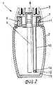
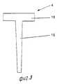
На фиг. 1 представлено продольное сечение дозирующего устройства; на фиг. 2 поперечное сечение дозирующего устройства; на фиг. 3 увеличенный боковой вид фитиля. In FIG. 1 shows a longitudinal section of a metering device; in FIG. 2 is a cross section of a metering device; in FIG. 3 enlarged side view of the wick.
Дозирующее устройство 1, которое может служить, например, в качестве освежителя воздуха, содержит контейнер 2, верхний колпачок 3, фитиль 4 и крышку 5, которая частично показана в левой части фиг. 1 и служит для закрывания дозирующего устройства до его ввода в действие, и пробку 6. The metering device 1, which can serve, for example, as an air freshener, comprises a
Пробка 6 является единой отливкой и закреплена на горловине контейнера 2 посредством защелкивающегося соединения 7 и содержит разбрызгивающее сопло 8, из которого выходит первый погруженный трубчатый канал 9 в точку вблизи дна контейнера. The
Далее пробка 6 содержит второй погруженный канал 10, выходящий из испарительного пространства 11 вокруг разбрызгивающего сопла вниз к месту вблизи дна контейнера. В нижнем конце погруженного трубчатого канала 10 устроен обратный клапан 12. Further, the
В представленном варианте осуществления изобретения обратный клапан 12 сконструирован в виде шарика 13, находящегося в радиальном зазоре в нижней части погруженного трубчатого канала 10 и удерживается в осевом зазоре двумя ограничителями, предусмотренными в канале 10, верхний ограничитель образуется седлом клапана 14 так, что канал 10 перекрывается шариком 13, когда возрастает давление в контейнере 2. In the presented embodiment, the
Фитиль 4 сделан из пористого поглощающего жидкость материала и имеет Т-образную форму. На фиг. 1 и 2 фитиль 4 не показан. Когда фитиль 4 вставлен в дозирующее устройство 1, ножка 15 Т-образного фитиля 4 располагается в погруженном канале 10, а перекрестья 16 Т-образного фитиля 4 напротив внутренней части стенки, окружающей испарительное пространство 11. Перекрестье 16 образует испарительную поверхность фитиля 4. The
Работа осуществляется следующим образом. Перед работой контейнер 2 должен быть частично заполнен жидким активным веществом. Содержащая активное вещество жидкость непрерывно поглощается фитилем и испаряется в испарительном пространстве, связанном с атмосферой. За счет сжатия контейнера большое количество жидкости может быть мгновенно разряжено через разбрызгивающее сопло. The work is as follows. Before work, the
Claims (6)
Translated fromRussianApplications Claiming Priority (3)
| Application Number | Priority Date | Filing Date | Title |
|---|---|---|---|
| NL9100089 | 1991-01-17 | ||
| NL9100089ANL9100089A (en) | 1991-01-17 | 1991-01-17 | EVAPORATOR WITH COMBINED CONTINUOUS AND INSTANTACTIVE OPERATION. |
| PCT/NL1992/000009WO1992012802A1 (en) | 1991-01-17 | 1992-01-16 | Dispenser adapted for combined continuous and instant operation |
Publications (2)
| Publication Number | Publication Date |
|---|---|
| RU2055648C1true RU2055648C1 (en) | 1996-03-10 |
| RU93052693A RU93052693A (en) | 1997-03-27 |
Family
ID=19858746
Family Applications (1)
| Application Number | Title | Priority Date | Filing Date |
|---|---|---|---|
| RU9293052693ARU2055648C1 (en) | 1991-01-17 | 1992-01-16 | Metering pump |
Country Status (25)
| Country | Link |
|---|---|
| US (1) | US5364027A (en) |
| EP (1) | EP0496460B1 (en) |
| JP (1) | JP2593031B2 (en) |
| KR (1) | KR0142074B1 (en) |
| AT (1) | ATE114512T1 (en) |
| AU (1) | AU647244B2 (en) |
| CA (1) | CA2100443C (en) |
| CZ (1) | CZ143293A3 (en) |
| DE (1) | DE69200718T2 (en) |
| DK (1) | DK0496460T3 (en) |
| ES (1) | ES2067999T3 (en) |
| FI (1) | FI108282B (en) |
| HK (1) | HK29996A (en) |
| HU (1) | HU214493B (en) |
| IE (1) | IE65896B1 (en) |
| MY (1) | MY117102A (en) |
| NL (1) | NL9100089A (en) |
| NO (1) | NO179779C (en) |
| NZ (1) | NZ241332A (en) |
| PL (1) | PL168066B1 (en) |
| RO (1) | RO113720B1 (en) |
| RU (1) | RU2055648C1 (en) |
| SK (1) | SK280040B6 (en) |
| WO (1) | WO1992012802A1 (en) |
| ZA (1) | ZA92297B (en) |
Cited By (4)
| Publication number | Priority date | Publication date | Assignee | Title |
|---|---|---|---|---|
| RU2323008C2 (en)* | 2003-04-16 | 2008-04-27 | Зобеле Испания, С.А. | Device usable in car for spraying compounds refreshing air |
| RU2443732C1 (en)* | 2007-12-13 | 2012-02-27 | Колгейт-Палмолив Компани | Pump dispensing head for flavoring substance |
| RU2458611C2 (en)* | 2007-10-25 | 2012-08-20 | Шанель Парфюм Боте | Device for preservation and reproduction of fragrance and complex of such devices |
| RU2599184C2 (en)* | 2011-04-14 | 2016-10-10 | Форд Глобал Технолоджис, ЛЛК | Method and device for air quality improvement in vehicle cabin |
Families Citing this family (59)
| Publication number | Priority date | Publication date | Assignee | Title |
|---|---|---|---|---|
| JP2599925Y2 (en) | 1993-06-08 | 1999-09-27 | 株式会社吉野工業所 | Air freshener container |
| JP2599926Y2 (en) | 1993-06-14 | 1999-09-27 | 株式会社吉野工業所 | Air freshener container |
| JP2603927Y2 (en) | 1993-06-15 | 2000-04-04 | 株式会社吉野工業所 | Air freshener container |
| US5976503A (en)* | 1997-04-14 | 1999-11-02 | S. C. Johnson & Son, Inc. | Disposable plug-in air freshener with heat activated cartridge |
| US6123935A (en)* | 1997-04-14 | 2000-09-26 | S. C. Johnson & Son, Inc. | Air freshener dispenser device with disposable heat-activated cartridge |
| US5903710A (en)* | 1997-04-14 | 1999-05-11 | S. C. Johnson & Son, Inc. | Air freshener dispenser device with disposable heat-promoted cartridge |
| US5945094A (en)* | 1997-04-14 | 1999-08-31 | S. C. Johnson & Son, Inc. | Disposable plug-in dispenser for use with air freshener and the like |
| FR2781770B1 (en) | 1998-07-30 | 2000-10-13 | Valois Sa | FLUID PRODUCT SAMPLE |
| GB9916755D0 (en)* | 1999-07-17 | 1999-09-15 | Reckitt & Colmann Prod Ltd | Improvements in or relating to organic compositions |
| GB2354711B (en)* | 1999-08-10 | 2003-10-29 | Johnson & Son Inc S C | Dual function dispenser |
| US6569387B1 (en)* | 1999-08-10 | 2003-05-27 | S.C. Johnson & Son, Inc. | Dual function dispenser |
| US6736335B2 (en)* | 2001-07-03 | 2004-05-18 | Lee Clayton Cuthbert | Scent dispensing packet |
| GB0123851D0 (en) | 2001-10-04 | 2001-11-28 | Pankhurst Design & Development | Dispersing fragrances |
| US6945473B2 (en)* | 2001-12-20 | 2005-09-20 | Valois S.A.S. | Fluid product dispenser |
| US6808684B2 (en) | 2002-04-05 | 2004-10-26 | International Flavors & Fragrance Inc. | Fragrance material |
| US6861031B2 (en)* | 2002-04-05 | 2005-03-01 | International Flavors & Fragrances Inc. | Fragrance material |
| ES2201930B1 (en)* | 2002-09-13 | 2005-03-01 | Tenko Ser 21, S.A. | MULTIFUNCTIONAL DOSER. |
| US20040176262A1 (en)* | 2002-09-18 | 2004-09-09 | Hammock Cory S. | Methods and compositions for drains and delivery lines |
| US7469844B2 (en) | 2002-11-08 | 2008-12-30 | S.C. Johnson & Son, Inc. | Diffusion device and method of diffusing |
| US6786427B2 (en)* | 2002-12-19 | 2004-09-07 | S. C. Johnson & Son, Inc. | Liquid sealing arrangements for replaceable liquid reservoirs |
| AU2003262668A1 (en)* | 2003-04-28 | 2004-11-23 | Ashland Inc. | Vehicle cabin air filter freshener |
| US6871794B2 (en) | 2003-05-01 | 2005-03-29 | E. I. Du Pont De Nemours And Company | Liquid dispersion device |
| GB2405097A (en)* | 2003-08-16 | 2005-02-23 | Reckitt Benckiser | Sensor equipped dispenser for air treatment media |
| US20060097065A1 (en)* | 2003-10-01 | 2006-05-11 | The Procter & Gamble Company | Methods for delivering volatile materials at different time periods |
| WO2005032607A2 (en)* | 2003-10-01 | 2005-04-14 | The Procter & Gamble Company | Systems and devices for delivering volatile materials |
| KR20060054483A (en)* | 2003-10-01 | 2006-05-22 | 더 프록터 앤드 갬블 캄파니 | Methods for delivering volatile materials |
| US7350720B2 (en) | 2004-02-03 | 2008-04-01 | S.C. Johnson & Son, Inc. | Active material emitting device |
| WO2005074999A1 (en) | 2004-02-03 | 2005-08-18 | S.C. Johnson & Son, Inc. | Device providing coordinated emission of light and volatile active |
| US7824627B2 (en) | 2004-02-03 | 2010-11-02 | S.C. Johnson & Son, Inc. | Active material and light emitting device |
| US7389943B2 (en) | 2004-06-30 | 2008-06-24 | S.C. Johnson & Son, Inc. | Electromechanical apparatus for dispensing volatile substances with single dispensing mechanism and cartridge for holding multiple receptacles |
| US20060076429A1 (en)* | 2004-10-12 | 2006-04-13 | The Procter & Gamble Company | Methods for delivering volatile materials |
| EP1874360A1 (en)* | 2005-03-29 | 2008-01-09 | The Dial Corporation | Fragrance delivery system |
| US7622073B2 (en) | 2005-04-12 | 2009-11-24 | S.C. Johnson & Son, Inc. | Apparatus for and method of dispensing active materials |
| US20060233538A1 (en)* | 2005-04-14 | 2006-10-19 | Tollens Fernando R | Energized systems and devices for delivering volatile materials |
| US20060231641A1 (en)* | 2005-04-14 | 2006-10-19 | Hirotaka Uchiyama | Devices with anti-leak features for delivering volatile materials |
| USD544085S1 (en) | 2005-12-08 | 2007-06-05 | The Dial Corporation | Air freshener housing |
| US20080056959A1 (en)* | 2006-08-31 | 2008-03-06 | Lee Cuthbert | Scent sampling devices and related methods |
| DE602006021762D1 (en)* | 2006-12-01 | 2011-06-16 | Procter & Gamble | Luftdesodorisierungsmittel |
| GB0707003D0 (en)* | 2007-04-11 | 2007-05-23 | Givaudan Sa | Device |
| CN101896092B (en)* | 2007-12-13 | 2013-05-01 | 高露洁-棕榄公司 | Fragrance dispensing pump head |
| US8320751B2 (en) | 2007-12-20 | 2012-11-27 | S.C. Johnson & Son, Inc. | Volatile material diffuser and method of preventing undesirable mixing of volatile materials |
| USD584809S1 (en) | 2008-02-04 | 2009-01-13 | S. C. Johnson & Son, Inc. | Dispensing device |
| USD639923S1 (en) | 2010-04-15 | 2011-06-14 | S.C. Johnson & Son, Inc. | Dispensing device |
| US8870030B2 (en) | 2011-02-04 | 2014-10-28 | S.C. Johnson & Son, Inc. | Attachment mechanism for a container |
| US8985398B2 (en) | 2011-02-04 | 2015-03-24 | S.C. Johnson & Son, Inc. | Attachment mechanism for a container |
| GB2492161B (en)* | 2011-06-24 | 2014-09-10 | Reckitt & Colman Overseas | Systems for improved delivery of volatile liquids |
| DE202012101580U1 (en) | 2012-04-27 | 2012-07-24 | S.C. Axeon Airfresh S.R.L. | Aroma diffusion device with vial |
| US8807540B2 (en) | 2012-06-12 | 2014-08-19 | S.C. Johnson & Son, Inc. | Fan-based volatile material dispensing system |
| US20140183273A1 (en)* | 2012-12-28 | 2014-07-03 | The Dial Corporation | Activating a volatile reservoir using a lateral force |
| JP6286258B2 (en)* | 2014-03-31 | 2018-02-28 | 株式会社吉野工業所 | Volatilization container |
| WO2018071725A1 (en) | 2016-10-12 | 2018-04-19 | Hya-scent, Inc. | Scent glass |
| US10953730B2 (en) | 2016-11-02 | 2021-03-23 | Christopher A. David | Air scenting system |
| USD980964S1 (en) | 2017-10-12 | 2023-03-14 | Hya-scent, Inc. | Fragrance diffuser element |
| USD894362S1 (en) | 2017-10-12 | 2020-08-25 | Hya-scent, Inc. | Fragrance diffuser |
| USD869630S1 (en) | 2017-10-12 | 2019-12-10 | Hya-scent, Inc. | Fragrance diffuser element |
| CN111818979A (en)* | 2018-03-06 | 2020-10-23 | 阿卜杜拉国王科技大学 | Method and apparatus for continuous extraction of salt from brine |
| US11623016B2 (en) | 2018-10-12 | 2023-04-11 | Hya-scent, Inc. | Scent diffuser |
| ES2818749A1 (en)* | 2019-10-09 | 2021-04-13 | Zobele Espana Sa | Volatile substance diffusion device (Machine-translation by Google Translate, not legally binding) |
| US20250177598A1 (en)* | 2022-03-04 | 2025-06-05 | Kokunet Teknoloji Anonim Sirketi | Scent dispenser and cartridge therefor |
Family Cites Families (13)
| Publication number | Priority date | Publication date | Assignee | Title |
|---|---|---|---|---|
| US897131A (en)* | 1907-10-07 | 1908-08-25 | Henry I Owen | Medicine-dropper. |
| US960008A (en)* | 1910-03-30 | 1910-05-31 | William V Evans | Oil-can. |
| US2520368A (en)* | 1948-09-20 | 1950-08-29 | Raymond W Landau | Dispenser for deodorants |
| US3972473A (en)* | 1974-11-21 | 1976-08-03 | Sterling Drug Inc. | Spray and evaporative air freshener combination |
| US4084732A (en)* | 1975-01-02 | 1978-04-18 | Dearling Harry S | Direct and indirect fragrance dispensing device |
| US4024992A (en)* | 1975-11-24 | 1977-05-24 | Schmid Hans G | Air atomizer bottle sprayer with screw cap |
| US4306679A (en)* | 1980-08-01 | 1981-12-22 | The Drackett Company | Dispenser for volatilizable substances |
| US4341348A (en)* | 1980-11-10 | 1982-07-27 | Dearling Neal S | Direct and indirect fragrance dispensing device |
| GB2105562A (en)* | 1981-09-11 | 1983-03-30 | Hara J B O | Drip dispensing apparatus |
| FR2556242B1 (en)* | 1983-12-07 | 1986-08-22 | Aerosol Inventions Dev | IMMEDIATE AND DELAYED DOUBLE ACTION ATMOSPHERE DIFFUSER, AND AEROSOL PACKAGING PROVIDED WITH SUCH A DIFFUSER |
| FR2569663B1 (en)* | 1984-08-28 | 1986-10-17 | Oreal | FLEXIBLE BOTTLE FOR PERFORMING EITHER SPRAYING, EITHER DRIPPING, OF A LIQUID IT CONTAINS |
| US4726519A (en)* | 1986-01-27 | 1988-02-23 | S. C. Johnson & Son, Inc. | Instant/continuous air-treatment device |
| WO1988008308A1 (en)* | 1987-04-29 | 1988-11-03 | The Commonwealth Industrial Gases Limited | Fluid dispenser |
- 1991
- 1991-01-17NLNL9100089Apatent/NL9100089A/ennot_activeApplication Discontinuation
- 1992
- 1992-01-15ZAZA92297Apatent/ZA92297B/enunknown
- 1992-01-16DEDE69200718Tpatent/DE69200718T2/ennot_activeExpired - Fee Related
- 1992-01-16HUHU9302050Apatent/HU214493B/ennot_activeIP Right Cessation
- 1992-01-16SKSK748-93Apatent/SK280040B6/enunknown
- 1992-01-16KRKR1019930702127Apatent/KR0142074B1/ennot_activeExpired - Fee Related
- 1992-01-16RURU9293052693Apatent/RU2055648C1/ennot_activeIP Right Cessation
- 1992-01-16AUAU11885/92Apatent/AU647244B2/ennot_activeCeased
- 1992-01-16CZCS931432Apatent/CZ143293A3/enunknown
- 1992-01-16EPEP92200124Apatent/EP0496460B1/ennot_activeExpired - Lifetime
- 1992-01-16DKDK92200124.3Tpatent/DK0496460T3/enactive
- 1992-01-16PLPL92300046Apatent/PL168066B1/ennot_activeIP Right Cessation
- 1992-01-16USUS08/090,213patent/US5364027A/ennot_activeExpired - Fee Related
- 1992-01-16WOPCT/NL1992/000009patent/WO1992012802A1/enactiveIP Right Grant
- 1992-01-16IEIE920135Apatent/IE65896B1/ennot_activeIP Right Cessation
- 1992-01-16ATAT92200124Tpatent/ATE114512T1/ennot_activeIP Right Cessation
- 1992-01-16CACA002100443Apatent/CA2100443C/ennot_activeExpired - Fee Related
- 1992-01-16JPJP4503310Apatent/JP2593031B2/ennot_activeExpired - Fee Related
- 1992-01-16RORO93-01001Apatent/RO113720B1/enunknown
- 1992-01-16ESES92200124Tpatent/ES2067999T3/ennot_activeExpired - Lifetime
- 1992-01-16MYMYPI92000075Apatent/MY117102A/enunknown
- 1992-01-17NZNZ241332Apatent/NZ241332A/ennot_activeIP Right Cessation
- 1993
- 1993-07-14FIFI933199Apatent/FI108282B/ennot_activeIP Right Cessation
- 1993-07-16NONO932587Apatent/NO179779C/ennot_activeIP Right Cessation
- 1996
- 1996-02-15HKHK29996Apatent/HK29996A/ennot_activeIP Right Cessation
Non-Patent Citations (1)
| Title |
|---|
| Заявка РСТ N 86/01438, кл. B 05B 11/04, 1986.* |
Cited By (4)
| Publication number | Priority date | Publication date | Assignee | Title |
|---|---|---|---|---|
| RU2323008C2 (en)* | 2003-04-16 | 2008-04-27 | Зобеле Испания, С.А. | Device usable in car for spraying compounds refreshing air |
| RU2458611C2 (en)* | 2007-10-25 | 2012-08-20 | Шанель Парфюм Боте | Device for preservation and reproduction of fragrance and complex of such devices |
| RU2443732C1 (en)* | 2007-12-13 | 2012-02-27 | Колгейт-Палмолив Компани | Pump dispensing head for flavoring substance |
| RU2599184C2 (en)* | 2011-04-14 | 2016-10-10 | Форд Глобал Технолоджис, ЛЛК | Method and device for air quality improvement in vehicle cabin |
Also Published As
Similar Documents
| Publication | Publication Date | Title |
|---|---|---|
| RU2055648C1 (en) | Metering pump | |
| US4084732A (en) | Direct and indirect fragrance dispensing device | |
| CN1700857B (en) | Delivery system for wicks having segments of different porosity | |
| US4235373A (en) | Fluid dispenser | |
| RU93052693A (en) | DOSING DEVICE | |
| RU2000114188A (en) | DEVICE FOR LIQUID STORAGE AND FOR ITS DELIVERY DROP | |
| US5645036A (en) | Fuel vapor capturing canister having increased distance of flow of fuel vapor passing through adsorbent layer | |
| AU7187800A (en) | Liquid atomizer | |
| JP2001088877A (en) | Aerosol container | |
| JP3229202B2 (en) | Container that has both spraying and transpiration functions | |
| US2310319A (en) | Liquid sprayer | |
| JPH0519067Y2 (en) | ||
| JPS607722Y2 (en) | volatile liquid dispenser | |
| RU2093276C1 (en) | Device for liquid spraying | |
| JPS5850917Y2 (en) | volatile liquid dispenser | |
| JPS5937251Y2 (en) | volatile liquid dispenser | |
| SU1174346A1 (en) | Reservoir for easily vaporable fluids | |
| JPH03240701A (en) | Heat evaporation device | |
| JPS6013480Y2 (en) | volatilization container | |
| JPH0220308B2 (en) | ||
| JPS62254861A (en) | Pressure generator | |
| MXPA06010199A (en) | Vapor dispensing device with vent having self-regulating pressure and self-cleaning features. |
Legal Events
| Date | Code | Title | Description |
|---|---|---|---|
| MM4A | The patent is invalid due to non-payment of fees | Effective date:20050117 |