RU2050206C1 - Vibrations energy transformation apparatus - Google Patents
Vibrations energy transformation apparatusDownload PDFInfo
- Publication number
- RU2050206C1 RU2050206C1RU93016333ARU93016333ARU2050206C1RU 2050206 C1RU2050206 C1RU 2050206C1RU 93016333 ARU93016333 ARU 93016333ARU 93016333 ARU93016333 ARU 93016333ARU 2050206 C1RU2050206 C1RU 2050206C1
- Authority
- RU
- Russia
- Prior art keywords
- resonator
- mechanical vibrations
- mechanical
- vibrations
- rods
- Prior art date
Links
- 230000009466transformationEffects0.000titleabstract3
- 238000006073displacement reactionMethods0.000claimsdescription11
- 239000006096absorbing agentSubstances0.000claimsdescription4
- 230000010355oscillationEffects0.000claimsdescription2
- 230000001131transforming effectEffects0.000claims1
- 239000000126substanceSubstances0.000abstract1
- 238000005452bendingMethods0.000description11
- 238000006243chemical reactionMethods0.000description4
- 239000002131composite materialSubstances0.000description3
- 239000007787solidSubstances0.000description2
- 238000010521absorption reactionMethods0.000description1
- 239000000853adhesiveSubstances0.000description1
- 238000004026adhesive bondingMethods0.000description1
- 230000001070adhesive effectEffects0.000description1
- 150000001875compoundsChemical class0.000description1
- 230000008878couplingEffects0.000description1
- 238000010168coupling processMethods0.000description1
- 238000005859coupling reactionMethods0.000description1
- 239000003292glueSubstances0.000description1
- 239000011343solid materialSubstances0.000description1
- 230000003068static effectEffects0.000description1
Images


Landscapes
- Apparatuses For Generation Of Mechanical Vibrations (AREA)
Abstract
Description
Translated fromRussianИзобретение относится к электроакустике и вибротехнике и может быть использовано для преобразования энергии электрических колебаний в энергию механических колебаний, а также для преобразования энергии механических колебаний в электрическую энергию или в тепловую. The invention relates to electroacoustics and vibration engineering and can be used to convert the energy of electrical vibrations into the energy of mechanical vibrations, as well as to convert the energy of mechanical vibrations into electrical energy or thermal.
Известен составной пьезоэлектрический преобразователь стержневого типа, содержащий полости в акустическом резонаторе (авт. св. СССР N 221403, кл. B 06 B 1/00, 1967). Преобразователь содержит соединенные с помощью клея пьезокерамические пластины, тыльные накладки и средний вкладыш с системой отверстий. A composite rod-type piezoelectric transducer containing cavities in an acoustic cavity is known (ed. St. USSR N 221403, class B 06
Основным недостатком известного преобразователя является недостаточно высокая механическая добротность, обусловленная наличием склейки. The main disadvantage of the known Converter is not a high mechanical figure of merit due to the presence of gluing.
Известен составной электроакустический преобразователь стержневого типа [1] содержащий монолитный акустический резонатор с полостью и крепежным элементом, расположенными в узловой области механических смещений резонатора, и пьезоэлемент, закрепленный с натягом в полости акустического резонатора. Отсутствие клеевых соединений позволяет увеличить добротность составного электроакустического преобразователя. Known composite rod-type electroacoustic transducer [1] containing a monolithic acoustic resonator with a cavity and a fastener located in the nodal region of the mechanical displacements of the resonator, and a piezoelectric element fixed with an interference fit in the cavity of the acoustic resonator. The absence of adhesive joints allows to increase the quality factor of a composite electro-acoustic transducer.
Недостатком указанного устройства является большой габаритный размер вдоль его продольной оси при заданной основной резонансной частоте преобразователя. The disadvantage of this device is the large overall dimension along its longitudinal axis for a given fundamental resonant frequency of the Converter.
Известно устройство для преобразования энергии колебаний [2] содержащее криволинейный резонатор механических колебаний с полостью и крепежным элементом и преобразующий элемент, закрепленный в полости резонатора механических колебаний с натягом. A device for converting vibrational energy [2] containing a curved resonator of mechanical vibrations with a cavity and a fastening element and a converting element mounted in the cavity of the resonator of mechanical vibrations with interference.
Выполнение резонатора механических колебаний криволинейным позволяет уменьшить габариты преобразователя при сохранении основной резонансной частоты. The execution of the resonator of mechanical vibrations curved allows you to reduce the dimensions of the Converter while maintaining the main resonant frequency.
Недостатком этого преобразователя является малое количество преобразованной энергии колебаний на низких частотах из-за большой изгибной жесткости стенки резонатора механических колебаний. The disadvantage of this Converter is the small amount of converted vibrational energy at low frequencies due to the large bending stiffness of the cavity wall of mechanical vibrations.
Целью изобретения является увеличение количества преобразованной энергии колебаний на низких частотах. The aim of the invention is to increase the amount of converted vibrational energy at low frequencies.
Цель достигается за счет того, что в устройство для преобразования энергии колебаний, содержащее криволинейный резонатор механических колебаний с полостью и крепежным элементом, преобразующий элемент, закрепленный с натягом в полости резонатора механических колебаний, дополнительно введены инерционные массы, а стенка резонатора механических колебаний выполнена с разрезами, образующими систему стержней, причем инерционные массы закреплены на соответствующих стержнях резонатора механических колебаний в пучности его смещений, а крепежный элемент резонатора механических колебаний выполнен с возможностью соединения с возбуждаемым элементом или с источником механических колебаний. The goal is achieved due to the fact that inertial masses are additionally introduced into the device for converting vibrational energy containing a curvilinear resonator of mechanical vibrations with a cavity and a fastening element, a converting element fixed with an interference fit in the cavity of the resonator of mechanical vibrations, and the wall of the resonator of mechanical vibrations is made with cuts forming a system of rods, and the inertial masses are fixed on the corresponding rods of the resonator of mechanical vibrations in the antinode of its displacements, and zhny mechanical vibrations of the resonator element is configured to be coupled to the excitable element or to a source of mechanical vibrations.
При этом преобразующий элемент может быть выполнен в виде пьезоэлемента, магнитостриктора или диссипативного поглотителя механических колебаний. In this case, the converting element can be made in the form of a piezoelectric element, magnetostrictor, or dissipative absorber of mechanical vibrations.
Крепежный элемент резонатора механических колебаний может быть расположен со стороны внешней или внутренней поверхности резонатора механических колебаний. The fastener of the mechanical vibration resonator may be located on the side of the external or internal surface of the mechanical vibration resonator.
Преобразующий элемент и крепежный элемент резонатора механических колебаний могут быть расположены по разные стороны или по одну сторону от плоскости поперечного сечения резонатора механических колебаний, проходящей через его собственный узел механических смещений. The converting element and the fastening element of the resonator of mechanical vibrations can be located on different sides or on the same side of the plane of the cross section of the resonator of mechanical vibrations passing through its own site of mechanical displacements.
Для возбуждения изгибных колебаний стержня центр инерции инерционной массы может быть расположен на продольной оси стержня резонатора механических колебаний. To excite bending vibrations of the rod, the center of inertia of the inertial mass can be located on the longitudinal axis of the rod of the resonator of mechanical vibrations.
Кроме того, для одновременного возбуждения изгибных и крутильных колебаний стержня центр инерции инерционной массы может быть смещен относительно продольной оси стержня резонатора механических колебаний. In addition, to simultaneously excite bending and torsional vibrations of the rod, the center of inertia of the inertial mass can be shifted relative to the longitudinal axis of the rod of the resonator of mechanical vibrations.
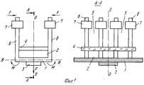
На фиг. 1 схематически изображено устройство для преобразования энергии колебаний, в котором крепежный элемент резонатора механических колебаний расположен со стороны внешней поверхности резонатора механических колебаний, а преобразующий элемент и крепежный элемент резонатора механических колебаний расположены по разные стороны от плоскости поперечного сечения резонатора механических колебаний, проходящей через его собственный узел механических смещений. In FIG. 1 schematically shows a device for converting vibrational energy, in which the fastening element of the mechanical vibration resonator is located on the side of the external surface of the mechanical vibration resonator, and the converting element and the fastening element of the mechanical vibration resonator are located on different sides of the cross-section plane of the mechanical vibration resonator passing through its own node of mechanical displacements.
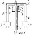
На фиг. 2 показан вариант устройства для преобразования энергии колебаний, в котором крепежный элемент резонатора механических колебаний расположен со стороны внутренней поверхности резонатора механических колебаний, а преобразующий элемент и крепежный элемент резонатора механических колебаний расположен по одну сторону от плоскости поперечного сечения резонатора механических колебаний, проходящей через собственный узел механических смещений. In FIG. 2 shows a variant of a device for converting vibrational energy, in which the fastening element of the mechanical vibration resonator is located on the side of the internal surface of the mechanical vibration resonator, and the converting element and the fastening element of the mechanical vibration resonator is located on one side of the cross-section plane of the mechanical vibration resonator passing through its own unit mechanical displacements.
На фиг. 3 показаны варианты размещения центра инерции инерционной массы относительно продольной оси стержня резонатора механических колебаний. In FIG. Figure 3 shows the placement of the center of inertia of the inertial mass relative to the longitudinal axis of the resonator rod of mechanical vibrations.
На фиг. 4 показан вариант устройства для преобразования энергии колебаний, в резонаторе механических колебаний которого возбуждаются одновременно изгибные и крутильные колебания стержней. In FIG. 4 shows a variant of a device for converting vibrational energy, in the resonator of mechanical vibrations of which both bending and torsional vibrations of the rods are excited.
Устройство содержит (фиг. 1) резонатор 1 механических колебаний с полостью 2 и крепежным элементом 3 резонатора 1 механических колебаний. В полости 2 с натягом закреплен преобразующий элемент 4. Натяг обеспечивается выбором размеров полости, преобразующего элемента и упругой статической деформацией контактирующих деталей. Стенка резонатора 1 механических колебаний выполнена с разрезами 5, которые образуют систему стержней 6. Стержни 6 резонатора 1 механических колебаний снабжены инерционными массами 7, размещенными в области пучности смещений резонатора 1 механических колебаний. Крепежный элемент 3 резонатора 1 механических колебаний выполнен с возможностью соединения с возбуждаемым элементом или с источником механических колебаний, что эквивалентно, поскольку каждое из перечисленных соединений обуславливает появление силы F (фиг. 1) или (и) момента М1 (фиг. 4), приложенных к крепежному элементу 3. The device contains (Fig. 1) a
Предложенная форма выполнения резонатора механических колебаний позволяет, с одной стороны, более равномерно и механически сильнее нагрузить преобразующий элемент, что приводит к увеличению коэффициента связи между преобразующим элементом и резонатором, с другой стороны, с помощью разрезов устраняются тангенциальные механические напряжения в стенке резонатора, что приводит к увеличению изгибающих моментов М (фиг. 1), действующих на отдельный стержень стенки резонатора. Снабжение стержней инерционными массами также увеличивает изгибающий момент М, амплитуду колебаний f (фиг. 1) стержней на низких частотах, а следовательно, и количество преобразованной энергии колебаний на низких частотах. The proposed embodiment of the mechanical vibration resonator allows, on the one hand, to load the converting element more uniformly and mechanically stronger, which leads to an increase in the coupling coefficient between the converting element and the resonator, on the other hand, by means of cuts, tangential mechanical stresses in the resonator wall are eliminated, which leads to increase the bending moments M (Fig. 1) acting on a separate rod of the cavity wall. The supply of rods with inertial masses also increases the bending moment M, the oscillation amplitude f (Fig. 1) of the rods at low frequencies, and therefore the amount of converted vibration energy at low frequencies.
Преобразующий элемент 4 может быть выполнен в виде пьезоэлемента, магнитостриктора или диссипативного поглотителя механических колебаний. The converting
Крепежный элемент 3 резонатора 1 механических колебаний может быть расположен со стороны внешней (фиг. 1) или внутренней (фиг. 2) поверхности резонатора 1 механических колебаний. The
Преобразующий элемент 4 и крепежный элемент 3 могут быть расположены по разные стороны (фиг. 1) или по одну сторону (фиг. 2) от плоскости поперечного сечения ВВ резонатора 1 механических колебаний, проходящей через его собственный узел механических смещений. The converting
Центр 8 инерции инерционной массы 7 может быть расположен как на продольной оси 0'0' стержня 6, так и быть смещен относительно продольной оси 0'0' стержня 6 (фиг. 3). The center of
В резонаторе 1 механических колебаний могут возбуждаться как изгибные (фиг. 1), так и изгибно-крутильные (фиг. 4) колебания стержней 6. Стрелки c и d на фиг. 4 указывают направления изгибно-крутильных колебаний стержней 6. In the
Резонатор 1 механических колебаний может быть выполнен из любого твердого материала с малым поглощением звука и иметь расположение стержней 6 в рядной (фиг. 1), осесимметричной или другой форме. Соответственно поперечное сечение полости 2 может быть в плане прямоугольным, круглым или другой формы. The
Крепежный элемент 3 может быть выполнен в виде пластины (фиг. 1), сплошного или полого стержня (фиг. 2) прямоугольного, круглого или любого другого сечения. The
Преобразующий элемент 4 может быть выполнен в виде пластины, стержня, пакета пластин или набора стержней, в виде одного общего для всех стержней 6 элемента (фиг. 1) или отдельных секций (фиг. 4). Отдельные секции преобразующего элемента 4 могут быть закреплены между стержнями 6 (фиг. 4) или между крепежным элементом 3 и одним из стержней 6. Преобразующий элемент 4 может быть закреплен в полости 2 как перпендикулярно оси 00 резонатора 1 механических колебаний (фиг. 1), так и параллельно оси 00 (фиг. 2), для чего на крепежном элементе 3 могут быть выполнены специальные выступы 9 (фиг. 2). The converting
Разрезы 5 стенки резонатора механических колебаний 1 могут быть выполнены как параллельно продольной оси резонатора 00 (фиг. 1), так и под углом к ней, и иметь искривленную или фигурную форму. The
Стержни 6 резонатора 1 механических колебаний могут быть прямолинейными или искривленными вдоль своей продольной оси, сплошными или трубчатыми, а в сечении иметь прямоугольную, круглую или любую другую форму. The
Резонатор 1 механических колебаний, его крепежный элемент 3, стержни 6 и инерционные массы 7 могут быть выполнены как за одно целое, так и в виде отдельных соединенных между собой деталей. The
Устройство работает следующим образом. В режиме преобразования энергии электрических колебаний при подаче на преобразующий элемент 4 (пьезоэлемент или магнитостриктор) электрического напряжения (см. фиг. 1) в преобразующем элементе 4 возникают механические колебания, которые через акустический контакт, обеспеченный натягом преобразующего элемента 4, передаются в резонатор 1 механических колебаний. При совпадении частоты электрического напряжения с собственной частотой резонатора 1 механических колебаний в последнем возбуждаются изгибные колебания стержней 6. При этом смещениям f стержней 6 соответствуют изгибающие моменты М и сила F, действующая со стороны крепежного элемента 3 на возбуждаемый элемент. При возбуждении в резонаторе 1 изгибно-крутильных колебаний стержней 6 (фиг. 4) на крепежном элементе 3 дополнительно к силе F возникает крутящий момент M1 относительно оси 00 резонатора 1 механических колебаний, который тоже передается на возбуждаемый элемент.The device operates as follows. In the mode of converting the energy of electrical vibrations when a voltage is applied to the transducer element 4 (piezoelectric element or magnetostrictor) (see Fig. 1), mechanical vibrations occur in the
В режиме преобразования энергии механических колебаний колебания источника механических колебаний через крепежный элемент 3 возбуждают резонатор 1 механических колебаний силой F (фиг. 1) или (и) крутящим моментом М1 относительно оси 00 (фиг. 4). В результате воздействия силы F или (и) крутящего момента М1 стержни 6 резонатора 1 механических колебаний совершают изгибные (фиг. 1) или изгибно-крутильные (фиг. 4) колебания, которые резонатором 1 механических колебаний трансформируются в продольные колебания преобразующего элемента 4. При совпадении частоты механических колебаний источника с собственной частотой резонатора 1 механических колебаний механические напряжения в преобразующем элементе 4 достигают максимальной величины, а энергия механических колебаний источника преобразуется преобразующим элементом 4 в электрическую энергию, если преобразующий элемент 4 выполнен в виде пьезоэлемента или магнитостриктора, или в тепловую энергию, если преобразующий элемент 4 выполнен в виде диссипативного поглотителя механических колебаний.In the mode of energy conversion of mechanical vibrations, the vibrations of the source of mechanical vibrations through the
При этом из-за уменьшения изгибной жесткости стенки резонатора 1 механических колебаний и увеличения инерционной массы, колеблющейся в пучности смещений резонатора 1 механических колебаний, увеличивается количество преобразованной энергии колебаний на низких частотах. Moreover, due to a decrease in the bending stiffness of the wall of the
Claims (7)
Translated fromRussianPriority Applications (1)
| Application Number | Priority Date | Filing Date | Title |
|---|---|---|---|
| RU93016333ARU2050206C1 (en) | 1993-03-30 | 1993-03-30 | Vibrations energy transformation apparatus |
Applications Claiming Priority (1)
| Application Number | Priority Date | Filing Date | Title |
|---|---|---|---|
| RU93016333ARU2050206C1 (en) | 1993-03-30 | 1993-03-30 | Vibrations energy transformation apparatus |
Publications (2)
| Publication Number | Publication Date |
|---|---|
| RU93016333A RU93016333A (en) | 1995-04-30 |
| RU2050206C1true RU2050206C1 (en) | 1995-12-20 |
Family
ID=20139472
Family Applications (1)
| Application Number | Title | Priority Date | Filing Date |
|---|---|---|---|
| RU93016333ARU2050206C1 (en) | 1993-03-30 | 1993-03-30 | Vibrations energy transformation apparatus |
Country Status (1)
| Country | Link |
|---|---|
| RU (1) | RU2050206C1 (en) |
- 1993
- 1993-03-30RURU93016333Apatent/RU2050206C1/enactive
Non-Patent Citations (2)
| Title |
|---|
| 1. Авторское свидетельство СССР N 1419749, кл. B 06B 1/00, 1986.* |
| 2. Патент СССР N 1731291, кл. B 06B 1/06, 1990.* |
Similar Documents
| Publication | Publication Date | Title |
|---|---|---|
| US4823041A (en) | Non-directional ultrasonic transducer | |
| JPH06504481A (en) | Device for ultrasonic vibration of non-tuned structures | |
| US4779020A (en) | Ultrasonic transducer | |
| RU2050206C1 (en) | Vibrations energy transformation apparatus | |
| Lin | Design of piezoelectric sandwich ultrasonic transducers with large cross-section | |
| SU623241A1 (en) | Vibromotor | |
| JPS6059900A (en) | Piezoelectric vibrator using buckling spring | |
| JPH07143770A (en) | Ultrasonic motor | |
| RU2230615C1 (en) | Sonic energy rod transducer | |
| RU2106205C1 (en) | Ultrasonic vibratory system with intermediate vibrator | |
| JPH0534848B2 (en) | ||
| JPH0311983A (en) | Driving method of ultrasonic motor and vibrator for ultrasonic motor | |
| JP3453838B2 (en) | Ultrasonic motor | |
| RU2020769C1 (en) | Piezoelectric bell | |
| SU1553303A1 (en) | Method of assembling parts | |
| JP7495690B2 (en) | Ultrasonic Complex Vibration Device | |
| RU220239U1 (en) | Piezoelectric generator with bimorph beam type transducer | |
| JPH0541823Y2 (en) | ||
| SU1731291A1 (en) | Compound electroacoustic flexural vibration transducer | |
| SU1419749A1 (en) | Composite electroacoustic transducer of rod type | |
| JPH0820071A (en) | Ultrasonic welding apparatus | |
| RU49363U1 (en) | Piezoelectric Acoustic Transducer (OPTIONS) | |
| RU2050038C1 (en) | Vibration transducer | |
| JPH06153546A (en) | Ultrasonic oscillator and ultrasonic actuator | |
| JP2874174B2 (en) | Ultrasonic transducer and ultrasonic motor |