RU2043638C1 - Telemetering device power cell - Google Patents
Telemetering device power cellDownload PDFInfo
- Publication number
- RU2043638C1 RU2043638C1SU4779870ARU2043638C1RU 2043638 C1RU2043638 C1RU 2043638C1SU 4779870 ASU4779870 ASU 4779870ARU 2043638 C1RU2043638 C1RU 2043638C1
- Authority
- RU
- Russia
- Prior art keywords
- photoconverter
- light
- photocell
- unit
- reflector
- Prior art date
Links
Images

Landscapes
- Photovoltaic Devices (AREA)
- Optical Communication System (AREA)
Abstract
Description
Translated fromRussianИзобретение относится к измерительной технике и может быть использовано для электропитания различных телеметрических или других устройств от приемно-регистрирующего блока или блока управления и расположенных в объемах, где затруднено обслуживание источников питания, в том числе на высоковольтных платформах, в замкнутых объемах (как правило трудно-доступных) и т.д. The invention relates to measuring equipment and can be used to power various telemetry or other devices from the receiving and recording unit or control unit and located in volumes where it is difficult to service power sources, including on high-voltage platforms, in closed volumes (as a rule it is difficult to available), etc.
Известен источник электропитания оптоэлектронных устройств, расположенных в объемах, где затруднена зарядка или обслуживание источников питания, включающий преобразование электроэнергии в излучение спектральной области А, которое через оптический фильтр вводится в оптическое волокно. На приемной стороне устройства это излучение преобразуется фотоэлектрическим преобразователем в электрическую энергию, необходимую для питания электрической схемы передающей части оптоэлектронного устройства. Для этого на входах оптических приемопередатчиков на передающей и приемной частях оптоэлектронных устройств устанавливаются оптические фильтры, пропускающие передаваемые по этому же волокну, соответственно в спектральных областях В и С сигналы передаваемых и принимаемых данных. A known power source of optoelectronic devices located in volumes where it is difficult to charge or maintain power sources, including the conversion of electricity into radiation of spectral region A, which is introduced through an optical filter into an optical fiber. On the receiving side of the device, this radiation is converted by the photoelectric converter into the electrical energy necessary to power the electrical circuit of the transmitting part of the optoelectronic device. To do this, optical filters are installed at the inputs of optical transceivers on the transmitting and receiving parts of optoelectronic devices, which transmit signals transmitted and received through the same fiber, respectively, in the spectral regions B and C of the transmitted and received data.
Наиболее близким к изобретению техническим решением (прототипом) является устройство передачи оптической энергии, по стандартному оптическому волокну с диаметром сердцевины от 150 до 300 мкм, к фотодиоду лазерного излучения с длиной волны от 0,7 до 1,7 мкм таким образом, что несколько лазеров запитывают отрезки оптоволокна, которые затем объединяются через согласующие устройства в общее передающее оптоволокно, а на приемном конце размещается аналогичная решетка из фотодиодов вольтаического типа. Недостаток прототипа низкая надежность работы обусловленная ограниченным диапазоном интенсивностей света, при которой еще возможно преобразование световой энергии в электрическую из-за термического разогрева полупроводникового фотоэлемента. The technical solution (prototype) closest to the invention is an optical energy transmission device, via a standard optical fiber with a core diameter of 150 to 300 μm, to a laser photodiode with a wavelength of 0.7 to 1.7 μm so that several lasers they feed segments of optical fiber, which are then combined through matching devices into a common transmitting optical fiber, and a similar array of voltaic type photodiodes is placed at the receiving end. The disadvantage of the prototype is the low reliability due to the limited range of light intensities, at which it is still possible to convert light energy into electrical energy due to thermal heating of the semiconductor photocell.
Цель изобретения повышение надежности и долговечности устройства. The purpose of the invention is to increase the reliability and durability of the device.
Сущность изобретения состоит в том, что в элементе питания устройств телеметрии, включающем оптическую цепь, содержащую последовательно оптически связанные по крайней мере один источник излучения, световод, устройство вывода излучения из световода и фотопреобразователь, устройство вывода излучения из световода выполнено в виде вогнутого сферического светорассеивающего отражателя и концентричного ему цилиндрического металлического отражателя. The essence of the invention lies in the fact that in the power element of the telemetry devices, including an optical circuit, containing at least optically coupled at least one radiation source, a fiber, a device for outputting radiation from a fiber and a photoconverter, the device for outputting radiation from a fiber is made in the form of a concave spherical light-scattering reflector and a concentric cylindrical metal reflector.
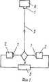
На фиг. 1 представлена функциональная схема устройства; на фиг. 2 узел фотопреобразователя, фронтальный разрез. In FIG. 1 shows a functional diagram of a device; in FIG. 2 photoconverter unit, frontal section.
На фиг. 1: 1 фокусирующие стержни; 2 светоизлучатели; 3 источник тока; 4 волоконно-оптический разветвитель; 5 световод; 6 фотопреобразователь. In FIG. 1: 1 focusing rods; 2 light emitters; 3 current source; 4 fiber optic splitter; 5 optical fiber; 6 photoconverter.
На фиг. 2: 1 фокусирующий стержень; 7 фотоэлемент; 8 металлический экран; 9 электроразъем; 10 сферический светорассеивающий отражатель; 11 цилиндрический металлический отражатель; 12 винты. In FIG. 2: 1 focusing rod; 7 photocell; 8 metal screen; 9 electrical connector; 10 spherical light diffusing reflector; 11 cylindrical metal reflector; 12 screws.
Элемент питания устройств телеметрии выполняется как составная часть телеметрического устройства и состоит из трех основных частей. Первая часть осветительная система, включающая, например, два светоизлучателя 2 и фокусирующих стержня 1, волоконно-оптический разветвитель 4 и источник тока 3. Вторая часть фотопреобразователь, включающий фокусирующий стержень 1, фотоэлемент 7, сферический светорассеивающий отражатель 10, цилиндрический металлический отражатель 11, металлический экран 8, электроразъем 9, винты 12. Третья часть световод 5. The power element of telemetry devices is performed as an integral part of a telemetry device and consists of three main parts. The first part is a lighting system, including, for example, two
При выключенном источнике тока 3 осветительной системы электрический ток на выходе фотопреобразователя отсутствует. When the
При поступлении напряжения на источник тока 3 свет от светоизлучателей 2 поступает на фокусирующие стержни 1 и дальше через волоконно-оптический разветвитель 4 по световоду 5 передается к фокусирующему стержню 1, входящему в состав блока фотопреобразователя. Затем свет попадает на сферический светорассеивающий отражатель 10, рассеиваясь на котором и отражаясь от цилиндрического металлического отражателя 11, попадает на фотоэлемент 7, где преобразуется в электрический ток. Электрический ток через электроразъем 9 передается телеметрическому или иному устройству, электропитание которого осуществляется. При этом за счет сферического светорассеивающего отражателя 10 и цилиндрического металлического отражателя 11 световой поток поступающий по световоду 5 равномерно распределяется по всей поверхности фотоэлемента 7, обеспечивая тем самым оптимальный термический режим его работы, а фотопреобразователь имеет приемлемые для практического использования массо-габаритные параметры. When voltage is supplied to the
Светоизлучатели, используемые в устройстве, могут быть объединены в группы, содержащие один или более светоизлучателей. Излучение от групп излучателей может быть передано по отдельному световоду к фотоэлектрическому блоку. При этом в фотопреобразующем блоке устанавливается несколько фокусирующих стержней, через которые оптическое излучение поступает на сферический светорассеивающий отражатель, цилиндрический металлический отражатель и на фотоэлемент. The light emitters used in the device can be combined into groups containing one or more light emitters. Radiation from groups of emitters can be transmitted through a separate fiber to the photovoltaic unit. At the same time, several focusing rods are installed in the photoconverting unit through which optical radiation enters the spherical light-scattering reflector, a cylindrical metal reflector, and the photocell.
Конструкция устройства дает возможность поместить все элементы фотопреобразователя в защитный экран, в том числе металлический. Тем самым исключается возможность воздействия на фотоэлемент различного рода дестабилизирующих факторов (электромагнитных наводок, загрязнений, влаги и т.д.), дополнительно повышая надежность его работы. The design of the device makes it possible to place all the elements of the photoconverter in a protective screen, including metal. This eliminates the possibility of exposure to the photocell of various kinds of destabilizing factors (electromagnetic interference, pollution, moisture, etc.), further increasing the reliability of its operation.
Claims (1)
Translated fromRussianPriority Applications (1)
| Application Number | Priority Date | Filing Date | Title |
|---|---|---|---|
| SU4779870RU2043638C1 (en) | 1990-01-08 | 1990-01-08 | Telemetering device power cell |
Applications Claiming Priority (1)
| Application Number | Priority Date | Filing Date | Title |
|---|---|---|---|
| SU4779870RU2043638C1 (en) | 1990-01-08 | 1990-01-08 | Telemetering device power cell |
Publications (1)
| Publication Number | Publication Date |
|---|---|
| RU2043638C1true RU2043638C1 (en) | 1995-09-10 |
Family
ID=21490284
Family Applications (1)
| Application Number | Title | Priority Date | Filing Date |
|---|---|---|---|
| SU4779870RU2043638C1 (en) | 1990-01-08 | 1990-01-08 | Telemetering device power cell |
Country Status (1)
| Country | Link |
|---|---|
| RU (1) | RU2043638C1 (en) |
- 1990
- 1990-01-08RUSU4779870patent/RU2043638C1/enactive
Non-Patent Citations (2)
| Title |
|---|
| Патент Великобритании N 2105712, кл. H 04B 9/00, 1979.* |
| Патент Японии 61-249435, кл. H 04B 9/00, 1983.* |
Similar Documents
| Publication | Publication Date | Title |
|---|---|---|
| US5128846A (en) | Light source | |
| US4467208A (en) | Radiation sensor containing fluorescible material | |
| US4883333A (en) | Integrated, solid, optical device | |
| US3886544A (en) | Keyboard using optical switching | |
| US6272269B1 (en) | Optical fiber/waveguide illumination system | |
| US6270244B1 (en) | Fiber optic illumination system having diffraction grating wavelength selector | |
| US9755745B2 (en) | Device for simultaneous data and power transmission over an optical waveguide | |
| KR950014912A (en) | Optical module for two-way transmission | |
| CN107917732B (en) | A kind of optical fiber geometric parameter, attenuation coefficient integrated test system | |
| MY111300A (en) | Optical device. | |
| KR880002738Y1 (en) | Artificial light source device | |
| US4976789A (en) | Power transmission device | |
| CA2411538A1 (en) | Beam combiner | |
| RU2043638C1 (en) | Telemetering device power cell | |
| CA1162431A (en) | Optical coupler for transmission and reception over optical fibre | |
| GB2116742A (en) | Apparatus for the transmission and distribution of light radiation | |
| JPS57158604A (en) | Light beam converting adaptor | |
| JP2003518616A (en) | Method and apparatus for measuring the spatial average intensity of a light beam and method and apparatus for adjusting a light source | |
| RU2696355C1 (en) | Fiber-optical photoelectric converter of laser radiation | |
| HUT73895A (en) | Light generator with reflective enclosure for a lighting or illuminating system using light guides | |
| SU1720126A1 (en) | Power transmission line | |
| Stokes | Coupling light from incoherent sources to optical waveguides | |
| JPS5734572A (en) | Exposure stabilization device | |
| CN212302114U (en) | Compact type remote target laser indicator structure | |
| CN108799930A (en) | Optical fiber illuminating system with optical feedback return circuit |