RU2036541C1 - Connecting strip for insulated cable conductors - Google Patents
Connecting strip for insulated cable conductorsDownload PDFInfo
- Publication number
- RU2036541C1 RU2036541C1SU914894713ASU4894713ARU2036541C1RU 2036541 C1RU2036541 C1RU 2036541C1SU 914894713 ASU914894713 ASU 914894713ASU 4894713 ASU4894713 ASU 4894713ARU 2036541 C1RU2036541 C1RU 2036541C1
- Authority
- RU
- Russia
- Prior art keywords
- strip
- contact
- housing
- bar
- strap
- Prior art date
Links
- 239000004020conductorSubstances0.000titleabstractdescription5
- 238000012360testing methodMethods0.000claimsdescription15
- 210000005069earsAnatomy0.000claimsdescription6
- 238000000926separation methodMethods0.000claimsdescription6
- 230000005540biological transmissionEffects0.000claimsdescription3
- 238000004891communicationMethods0.000claimsdescription3
- 238000012545processingMethods0.000claimsdescription3
- 230000015572biosynthetic processEffects0.000claims1
- 210000003462veinAnatomy0.000claims1
- 238000004870electrical engineeringMethods0.000abstract1
- 239000000126substanceSubstances0.000abstract1
- 238000003780insertionMethods0.000description21
- 230000037431insertionEffects0.000description21
- 210000002105tongueAnatomy0.000description18
- 229920002994synthetic fiberPolymers0.000description7
- 238000009413insulationMethods0.000description2
- 239000002184metalSubstances0.000description2
- 230000001012protectorEffects0.000description2
- 238000013461designMethods0.000description1
- 238000007373indentationMethods0.000description1
- 238000002955isolationMethods0.000description1
- 239000007769metal materialSubstances0.000description1
- 238000005192partitionMethods0.000description1
- 230000008707rearrangementEffects0.000description1
Images


Classifications
- H—ELECTRICITY
- H01—ELECTRIC ELEMENTS
- H01R—ELECTRICALLY-CONDUCTIVE CONNECTIONS; STRUCTURAL ASSOCIATIONS OF A PLURALITY OF MUTUALLY-INSULATED ELECTRICAL CONNECTING ELEMENTS; COUPLING DEVICES; CURRENT COLLECTORS
- H01R11/00—Individual connecting elements providing two or more spaced connecting locations for conductive members which are, or may be, thereby interconnected, e.g. end pieces for wires or cables supported by the wire or cable and having means for facilitating electrical connection to some other wire, terminal, or conductive member, blocks of binding posts
- H01R11/11—End pieces or tapping pieces for wires, supported by the wire and for facilitating electrical connection to some other wire, terminal or conductive member
- H01R11/20—End pieces terminating in a needle point or analogous contact for penetrating insulation or cable strands
- H—ELECTRICITY
- H01—ELECTRIC ELEMENTS
- H01R—ELECTRICALLY-CONDUCTIVE CONNECTIONS; STRUCTURAL ASSOCIATIONS OF A PLURALITY OF MUTUALLY-INSULATED ELECTRICAL CONNECTING ELEMENTS; COUPLING DEVICES; CURRENT COLLECTORS
- H01R9/00—Structural associations of a plurality of mutually-insulated electrical connecting elements, e.g. terminal strips or terminal blocks; Terminals or binding posts mounted upon a base or in a case; Bases therefor
- H01R9/22—Bases, e.g. strip, block, panel
- H01R9/24—Terminal blocks
- H01R9/2425—Structural association with built-in components
- H01R9/2441—Structural association with built-in components with built-in overvoltage protection
- H—ELECTRICITY
- H04—ELECTRIC COMMUNICATION TECHNIQUE
- H04Q—SELECTING
- H04Q1/00—Details of selecting apparatus or arrangements
- H04Q1/02—Constructional details
- H04Q1/14—Distribution frames
- H04Q1/142—Terminal blocks for distribution frames
Landscapes
- Engineering & Computer Science (AREA)
- Computer Networks & Wireless Communication (AREA)
- Connections Arranged To Contact A Plurality Of Conductors (AREA)
- Communication Cables (AREA)
- Structure Of Telephone Exchanges (AREA)
- Connections By Means Of Piercing Elements, Nuts, Or Screws (AREA)
- Processing Of Terminals (AREA)
Abstract
Description
Translated fromRussianИзобретение касается присоединительных пленок для подключения изолированных кабельных жил, в частности кабельных жил техники дальней связи и обработки, передачи и приема данных. The invention relates to connecting films for connecting insulated cable cores, in particular cable cores of long-distance communication equipment and processing, transmission and reception of data.
Известна присоединительная планка, которая состоит из трех корпусов, которые, находясь друг над другом, вставлены в язычки, выступающие через фиксирующие устройства на обеих торцевых сторонах корпусов планки, причем верхний и нижний корпуса планки снабжены ножевыми клеммными контактными элементами, которые последовательно расположены друг за другом, а каждый ножевой клеммный контактный элемент содержит два пружинящих контактных выступа, которые ограничивают расположенный посередине контактный шлиц (1). Known connecting strip, which consists of three cases, which, being one above the other, are inserted into the tabs, protruding through the locking device on both end faces of the case bodies, and the upper and lower case bodies are equipped with knife terminal contact elements that are arranged in series with each other and each knife terminal contact element contains two spring contact protrusions that limit the contact slot located in the middle (1).
Подлежащая присоединению изолированная кабельная жила с помощью инструмента вдавливается в контактный шлиц, причем острые кромки контактных выступов разрезают изоляцию кабельных жил и создают электрическое контактное соединение с проводящим электрический ток сердечником кабельных жил. Вставка и вдавливание изолированных кабельных жил в контактный шлиц происходит с верхней стороны каждого корпуса планки в направлении к его нижней стороне. Следовательно, для присоединения кабельных жил должен иметься свободный доступ к верхней стороне, соответственно присоединительной стороне каждого корпуса планки. The insulated cable core to be connected is pressed into the contact slot with a tool, and the sharp edges of the contact protrusions cut the insulation of the cable cores and create an electrical contact connection with the cable core conducting electric current. The insertion and indentation of insulated cable cores into the contact slot takes place on the upper side of each strip body in the direction of its lower side. Therefore, to connect the cable cores must have free access to the upper side, respectively, the connecting side of each housing of the strip.
Однако в известной присоединительной планке имеется недостаток, заключающийся в том, что при присоединении изолированных кабельных жил к ножевым клеммным контактным элементам среднего корпуса планки сначала необходимо снять с язычков верхний корпус планки. Лишь тогда будет обеспечен доступ к верхней стороне среднего корпуса планки для того, чтобы обеспечить контактирование кабельных жил с ножевыми клеммными контактными элементами. Последующие переранжировки кабельных жил, уже подключенных к среднему корпусу планки, более не являются возможными, так как кабельные жилы, присоединенные к верхнему корпусу планки, препятствуют снятию верхнего корпуса планки. Кроме того, в качестве дополнительных конструктивных элементов требуются боковые язычки для вставки трех корпусов планки. However, there is a drawback in the known connecting strip, in that when connecting the insulated cable cores to the knife terminal contact elements of the middle housing of the bracket, it is first necessary to remove the upper housing of the bracket from the tongues. Only then will access to the upper side of the middle body of the strap be provided in order to ensure contact of the cable cores with the knife terminal contact elements. Subsequent rearrangements of cable cores already connected to the middle body of the bar are no longer possible, since cable cores attached to the upper body of the bar prevent the removal of the upper case of the bar. In addition, side tabs for inserting three plank bodies are required as additional structural elements.
Целью изобретения является упрощение конструкции и обеспечение присоединения кабельных жил к ножевым клеммным контактным элементам корпусов планки и удаления кабельных жил с ножевых клеммных контактных элементов корпусов планки, исключая, чтобы один корпус планки препятствовал присоединениям других корпусов планки. The aim of the invention is to simplify the design and ensure the connection of cable cores to the knife terminal contact elements of the bar bodies and the removal of cable cores from the knife terminal contact elements of the bar bodies, except that one bar body interferes with the connections of the other bar bodies.
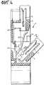
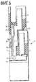
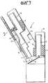
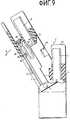
На фиг.1 изображена присоединительная планка, поперечный разрез в первом варианте исполнения; на фиг. 2 то же, с повернутом в наружном направлении нижним корпусом планки; на фиг.3 то же, в качестве разделительной планки; на фиг. 4 то же, с повернутым в наружном направлении нижним корпусом планки; на фиг. 5 присоединительная планка, частично вырезанная; на фиг.6 то же, вид спереди (второй вариант); на фиг.7 то же, с повернутым в наружном направлении верхним корпусом; на фиг.8 то же, в качестве разделительной планки; на фиг. 9 то же, с повернутым в наружном направлении корпусом планки; на фиг.10 поперечный разрез через присоединительную планку (третий вариант); на фиг.11 то же, вид сбоку; на фиг.12 то же, вид сверху. Figure 1 shows the connecting strip, a cross section in the first embodiment; in FIG. 2 the same, with the lower case body turned outwardly; figure 3 the same as a dividing bar; in FIG. 4 the same, with the lower case body turned outwardly; in FIG. 5 connecting strip, partially cut out; Fig.6 is the same front view (second option); Fig. 7 is the same with the upper body turned outwardly; Fig. 8 is the same as a dividing bar; in FIG. 9 the same, with the case body turned outwardly; figure 10 is a cross-section through the connecting strip (third option); 11 is the same side view; 12 is the same, top view.
На чертежах приняты следующие обозначения:
1 присоединительная планка, 2 разделительная планка, 3 верхний корпус планки, 4 наружный корпус планки, 5 поворотная ось, 6 сторона основания, 7 соединительный элемент, 8,9 ножевые клеммные контактные элементы, 10 присоединительная сторона, 11 сторона основания, 12 клеммный элемент, 13 задняя сторона, 14 магазин разрядников защиты от перенапряжений, 15, 16 контактные выступы, 17 контактный шлиц, 18 направляющий наклон, 19 край контактных выступов 15 и 16, 20, 21 концы соединительного элемента 7, 22 поворотная цапфа, 23 опора, 24 язычок, 25 вставной канал, 26 вставной язычок, 27 испытательный штекер, 28 упор, 29 шлицевой край, 30 контактный язычок, 31 место раздела, 32 пружинящий язычок, 33 контактное ушко, 34 контактный приемник, 35 упор, 36 боковая стенка, 37 пружинный язычок, 38 противоконтакт, 39 контактный выступ, 40 сторона основания, 41 отверстие, 42 нижняя сторона контактного элемента 8, 43 насадка, 44 фиксирующий крюк, 45 выемка, 101 нижний корпус планки, 102 верхний корпус планки, 103 магазин разрядников защиты от перенапряжений, 104 нижняя часть кожуха нижнего корпуса планки, 105 верхняя часть кожуха нижнего корпуса планки, 106 присоединительный элемент, 107 ножевой клеммный контактный элемент, 108 средний контакт, 109 отводной контакт, 110 клеммный шлиц, 111 контакт магазина, 112 приемный канал, 113 разрядник защиты от перенапряжений, 114 нижняя часть верхнего корпуса 102, 115 верхняя часть верхнего корпуса 102, 116 присоединительный элемент, 117 ножевой клеммный контактный элемент, 118 контактное ушко, 119 приемная ванна, 120 клеммный элемент, 121 испытательное контактное ушко, 122 часть стенки, 123 вставное отверстие, 124, 125 контактные пружины, 126 место раздела, 127 пластина основания, 128 фиксирующий элемент, 129, 130, 131 проволочные проводки, 132 корпус из синтетического материала, 133 шина заземления и 134 контактный палец.In the drawings, the following notation:
1 connecting strip, 2 separation strip, 3 upper strip housing, 4 outer strip housing, 5 rotary axis, 6 base side, 7 connecting element, 8.9 knife terminal contact elements, 10 connecting side, 11 base side, 12 terminal element, 13 rear side, 14 store surge arresters, 15, 16 contact ledges, 17 contact slot, 18 guide tilt, 19 edge of
Первый вариант исполнения присоединительной планки 1, представленный на фиг. 1-5, содержит изготовленное из синтетического материала тело корпуса, состоящее из двух корпусов 3, 4 планки. На стороне основания 11 присоединительной планки 1 выполнены дугообразные клеммные элементы 12 для закрепления на неизображенных стержнеобразных направляющих. Корпуса 3, 4 планки содержат несколько последовательно расположенных ножевых клеммных контактных элементов 8, 9, которые состоят из металлического материала и имеют два пружиняющих контактных выступа 15, 16, ограничивающих контактный шлиц 17. Для лучшего введения кабельной жилы в контактный шлиц 17 каждый ножевой клеммный контактный элемент 8, 9 имеет на своем верхнем конце направляющий наклон 18. Подлежащая подсоединению кабельная жила вводится с верхней стороны корпусов 3, 4 планки в соответствующей ножевой клеммный контактный элемент 8, 9 и вдавливается в направлении к нижней стороне каждого корпуса 3, 4 планки в соответствующий контактный шлиц 17 так, что острые края 19 контактных выступов 15, 16 разрезают изоляцию кабельной жилы и проникают в проводящий электрический ток сердечник кабельной жилы, чтобы обеспечить электрическое контактное соединение между ножевым клеммным контактным элементом 8, (9) и кабельной жилой. The first embodiment of the connecting
На фиг.1 показаны два корпуса 3, 4 планки, которые расположены друг над другом в присоединительной планке 1. К ножевым клеммным контактным элементам 9 нижнего корпуса 4 планки присоединяются кабельные жилы, соответственно присоединительные жилы приходящей стороны. К ножевым клеммным контактным элементам 8 верхнего корпуса 3 планки присоединяются кабельные жилы соответственно ранжировочные жилы отходящей стороны. Электрическое соединение между ножевым клеммным контактным элементом 8 верхнего корпуса 3 планки и ножевым клеммным контактным элементом 9 нижнего корпуса 4 планки происходит посредством соединительного элемента 7, выполненного из гибкой металлической ленты, концы 20, 21 которой соответственно соединены с ножевыми клеммными контактными элементами 8, 9. С соединительным элементом 7 соединен пружинящий язычок 24, который входит во вставной канал 25 присоединительной планки 1, служащий для приема вставного язычка 26 испытательного штекера 27, который после вставки электрически контактирует посредством пружинящего язычка 28 с ножевыми клеммными контактными элементами 8, 9. Figure 1 shows two
Нижний корпус 4 планки имеет поворотную ось 5 с поворотными цапфами 22, расположенными на торцевых сторонах нижнего корпуса 4 планки, которые входят в опорные отверстия 23 присоединительной планки 1. The
Для присоединения изолированных кабельных жил к ножевым клеммным контактным элементам 9 нижнего корпуса 4 планки он поворачивается в направлении стрелки А вперед от присоединительной планки 1 (см. фиг.2). После поворота нижнего корпуса 4 планки обеспечивается свободный доступ к его присоединительной стороне 10 для того, чтобы теперь вставить изолированные кабельные жилы в контактные шлицы 17 и вдавить их сверху с помощью непредставленного инструмента в контактные шлицы 17. После монтажа всех ножевых клеммных контактных элементов 9 нижний корпус 4 планки снова поворачивается в направлении к присоединительной планке 1 до тех пор, пока он снова не займет свое первоначальное положение, представленное на фиг.1. Как показано на фиг.2, гибкий соединительный элемент 7 вследствие поворотного движения нижнего корпуса 4 планки прижимается в направлении к задней стороне 13 присоединительной планки 1. Для предотвращения слишком большого поворота в наружном направлении нижнего корпуса 4 планки внутри присоединительной планки 1 предусмотрен упор 28, в который упирается шлицевой край 29 нижнего корпуса 4 планки. Упор служит для контактирования с магазином 14 разрядников защиты от перенапряжений, расположенным на задней стороне 13 присоединительной планки 1. На внутренних сторонах внутренних поверхностей предусмотренного в присоединительной планке 1 приемного отверстия для нижнего корпуса 4 планки закреплены фиксирующие крюки 44, которые после обратного поворота нижнего корпуса 4 планки входят в зацепление с выемками 45 нижнего корпуса 4 планки. To connect the insulated cable cores to the knife
После присоединения приходящих кабельных жил к ножевым клеммным контактным элементам 9 нижнего корпуса 4 планки отходящие кабельные жилы присоединяются к ножевым клеммным контактным элементам 8 верхнего корпуса 3 планки, который образует жесткую составную часть корпуса присоединительной планки 1. After attaching the incoming cable cores to the knife
На фиг.3 и 4 представлена выполненная в качестве разделительной планки 2 присоединительная планка 1. Разделительная планка 2 имеет между ножевыми клеммными контактными элементами 8, 9 место раздела 31, для чего ножевой клеммный контактный элемент 9 содержит пружинящий язычок 32, который входит во вставной канал 25 и контактирует со вставным язычком 26 штекера, в частности испытательного штекера 27. Ножевой клеммный контактный элемент 8 верхнего корпуса 3 планки содержит контактное ушко 33, которое также входит во вставной канал 25 и контактирует со вставным язычком 26 испытательного штекера 27, когда он вставлен в разделительную планку 2. Также и в случае разделительной планки 2 согласно фиг.3 и 4 нижний корпус 4 планки может поворачиваться вперед в направлении стрелки А для подключения кабельных жил, причем нижний корпус 4 планки также поворачивается вокруг поворотной оси 5, как это показано на фиг.4. Figures 3 and 4 show a connecting
На фиг.6-9 представлен второй вариант исполнения присоединительной планки 1. В этом случае в отличие от вышеописанного первого варианта исполнения нижний корпус 4 планки является жесткой составной частью присоединительной планки 1, в то время как верхний корпус 3 планки может поворачиваться вокруг поворотной оси 5, чтобы обеспечить доступ к присоединительному полю 10 нижнего корпуса 4 планки для присоединения изолированных кабельных жил. Присоединительная планка 1 согласно фиг.6 содержит оба корпуса 3,4 планки с соответственно одним рядом ножевых контактных элементов 8, 9, причем оба ряда обоих корпусов 3 и 4 планки соединены посредством гибкого соединительного элемента 7. На ножевом клеммном контактном элементе 8 предусмотрен пружинящий язычок 24, который входит во вставной канал 25, предусмотренный в верхнем корпусе 3 планки. Пружинящий язычок 24 продлен вниз и имеет контактный приемник 34, в который вставлен контактный язычок 30 магазина 14 разрядников защиты от перенапряжений. Figures 6 through 9 show a second embodiment of a connecting
Для присоединения изолированных кабельных жил к нижнему корпусу 4 планки верхний корпус 3 планки поворачивается в направлении стрелки В вокруг поворотной оси 5, как это показано на фиг.7. Поворотная ось 5 находится в области стороны основания 40 верхнего корпуса 3 планки. После его поворота в наружном направлении имеется свободный доступ к присоединительному полю 10 нижнего корпуса 4 планки так, что кабельные жилы могут быть вставлены сверху в контактный шлиц 17 нижнего корпуса 4 планки и вдавлены с помощью непредставленного инструмента в контактные шлицы 17 ножевых клеммных контактных элементов 9. После присоединения всех кабельных жил к ножевым контактным элементам 9 нижнего корпуса 4 планки верхний корпус 3 планки поворачивается обратно до тех пор, пока упор 35 приемного отверстия верхнего корпуса 3 планки не будет упираться в заднюю стенку 36 нижнего корпуса 4 планки. Верхний корпус 3 планки теперь снова занял свое первоначальное положение, причем верхний корпус 3 планки снова фиксируется с присоединительной планкой 1, соответственно с нижним корпусом 4 планки посредством фиксирующих крюков 44, входящих в зацепление с выемками 45. To connect the insulated cable cores to the
На фиг.8 и 9 представлен второй вариант присоединительной планки 1, выполненной в качестве разделительной планки 2. Разделительная планка 2 также содержит два корпуса 3, 4 планки, из которых верхний корпус 3 планки шарнирно присоединен с возможностью поворота к присоединительной планке 1, соответственно к нижнему корпусу 4 планки. Ножевой клеммный контактный элемент 8 верхнего корпуса 3 планки имеет на своей нижней стороне 42 контактный пружинящий язычок 37, который пружинисто прилегает к противоконтакту 38, соединенному с контактным выступом 39, который снова соединен посредством соединительного элемента 7 с ножевым клеммным контактным элементом 9 нижнего корпуса 4 планки. Между противоконтактным 38 и пружинящим язычком 37 образовано место раздела 31, которое может быть разделено с помощью непредставленного разделительного штекера, который может быть вставлен через отверстие 41 разделительной планки 2. Контактный выступ 39 имеет контактный приемник 34, в который может быть вставлен контактный язычок 30 магазина 14 разрядников защиты от перенапряжений. Как показано на фиг.9 также и в случае разделительной планки 2 верхний корпус 3 планки может поворачиваться наружу в направлении стрелки В так, что будет иметься свободный доступ к переключательному полю нижнего корпуса 4 планки. On Fig and 9 presents a second variant of the connecting
В случае второго варианта исполнения присоединительной планки 1 возможно также выполнять поворотные цапфы 22 с возможностью вставки в опору 23 так, что верхний корпус 3 планки установлен с возможностью вставки и поворота вокруг поворотной оси 5 в нижнем корпусе 4 планки. In the case of the second embodiment of the connecting
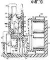
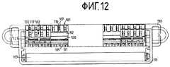
Представленный на фиг.10-12 третий вариант исполнения присоединительной планки для кабельных жил техники дальней связи состоит из нижнего корпуса 101 планки, к которому прифланцован магазин 103 разрядников защиты от перенапряжений и из верхнего корпуса 102 планки. Presented in FIGS. 10-12, a third embodiment of a connecting strip for cable conductors of telecommunication equipment consists of a
Кожух нижнего корпуса 101 планки состоит из нижней части 104 и верхней части 106, которые образованы из синтетического материала и скреплены друг с другом. В нижнем корпусе 101 планки предусмотрен ряд присоединительных элементов 106, которые состоят из ножевого клеммного контактного элемента 107, вилкообразного среднего контакта 108 и отводного контакта 109. Каждому ножевому клеммному контактному элементу 107 придан клеммный шлиц 110 в нижнем корпусе 101 планки, в котором может быть зажата неизображенная приходящая кабельная жила при контактировании с ножевым клеммным контактным элементом 107. Магазин 103 разрядников защиты от перенапряжений входит в зацепление своими магазинными контактами 111 с отводными контактами 109 присоединительных элементов 106 и таким образом защищает каждый отдельный присоединительный элемент 106 посредством разрядников 113 защиты от перенапряжений магазина 103 разрядников защиты от перенапряжений. На верхней стороне нижнего корпуса 101 планки выполнен проходящий в ее продольном направлении приемный канал 112 для вставки верхнего корпуса 102 планки. The casing of the
Верхний корпус 102 планки представляет собой корпус, состоящий из верхней части 115 и нижней части 114, которые соответственно образованы из синтетического материала и скреплены друг с другом. В верхнем корпусе 102 планки предусмотрены присоединительные элементы 116, которые образованы соответственно ножевым клеммным контактным элементом 117 и электрически с ним соединенным контактным ушком 118. Контактные ушки 118 верхнего корпуса 102 планки при его вставке в нижний корпус 101 планки входят в зацепление с соответствующими вилкообразными средними контактами 108 нижнего корпуса 101 планки, как это представлено на фиг.10. Ножевые клеммные контактные элементы 117 верхнего корпуса 102 планки находятся в области клеммных элементов 120, выполненных в верхнем корпусе 102 планки, которые зажимают подлежащие присоединению отходящие кабельные жилы при контакте ножевых клеммных контактных элементов 117 верхнего корпуса 102 планки. The
Верхний корпус 102 планки имеет непосредственное соединение ножевых клеммных контактных элементов 117 с контактными ушками 118, как это показано сплошными линиями на фиг.10, причем присоединительный элемент 116 выполнен цельным и образован вместе с контактным ушком 118 как дважды отогнутая металлическая лента. The
Для исполнения испытательного отвода контактное ушко 118 снабжено испытательным контактным ушком 121, проходящим в направлении ножевого клеммного контактного элемента 117, который прилегает к внешней стороне части 122 стенки, ограничивающей вставное отверстие 123, которое выполнено в верхней стороне верхнего корпуса 102 планки. Таким образом, через вставное отверстие 123 в верхний корпус 102 планки может быть вставлен испытательный штекер, который контактирует с испытательным контактным ушком 121 и благодаря этому с присоединительным элементом 116. For the execution of the test tap, the
Как показано штриховыми линиями на фиг.1, ножевые клеммные контактные элементы 117 верхнего корпуса 102 планки и их контактные ушки 118 соответственно могут быть снабжены контактными пружинами 124, 125, которые под вставным отверстием 123 образуют место раздела 126 для вставления разделительного штекера. Контактный палец 134 на контактной пружине 124 создает контактное соединение с контактной пружиной 125. Обе контактные пружины 124, 125 пружинисто прилегают своими свободными концами к внешней стороне частей 122 стенки, которые ограничивают вставное отверстие 123. Благодаря вставке разделительных штекеров во вставные отверстия 123 могут быть разделены места раздела 126 присоединительных элементов 116, а благодаря вставке испытательных штекеров контактные соединения между ножевыми клеммными контактными элементами 107, 117 проводятся через испытательные штекеры. Образованная таким образом присоединительная планка 100 образует разделительную планку. As shown by the dashed lines in FIG. 1, the knife
Присоединительная планка, состоящая из нижнего корпуса 101 и верхнего корпуса 102 планки, содержит пластину 127 основания, представленную только на фиг. 12 и 13, с фиксирующими элементами 128 для фиксирования на неизображенных параллельных несущих стержнях. Кроме того, пластина 127 основания содержит проволочные проводки 129-131. Для образования приемного пространства для магазина 103 разрядников защиты от перенапряжений предусмотрена приемная ванна 119, выполненная из синтетического материала, которая проходит до торцевых сторон присоединительной планки в области проволочных проводок 130. Магазин разрядников защиты от перенапряжений состоит из корпуса 132 из синтетического материала для приема разрядников 113 защиты от перенапряжений, которые одной контактной пластиной прилегают к контактам магазина, а другой контактной пластиной прилегают к шине 133 заземления, которая охватывает открытую нижнюю сторону корпуса 132 из синтетического материала. The connecting strip, consisting of the
Как показано на фиг. 10, плоскости рядов ножевых клеммных контактных элементов 107, 117 нижней частичной планки 101, соответственно верхней частичной планки 102 лежат в плоскостях, смещенных в боковом направлении. Благодаря этому возможен доступ также и к ряду ножевых клеммных контактных элементов 107 нижнего корпуса 101 планки с целью проведения монтажа при надетом верхнем корпусе 102 планки, когда ни верхний корпус 102 планки не выполнен немного более узким, чем показано на фиг.10, ни ножевые клеммные контактные элементы 107 нижнего корпуса 101 планки не установлены под небольшим наклоном. As shown in FIG. 10, the planes of the rows of knife
Claims (8)
Translated fromRussianApplications Claiming Priority (4)
| Application Number | Priority Date | Filing Date | Title |
|---|---|---|---|
| DE4008388ADE4008388A1 (en) | 1990-03-13 | 1990-03-13 | Insulated cable core connector moulding for telecommunication appts. |
| DE4008386ADE4008386A1 (en) | 1990-03-13 | 1990-03-13 | Insulated cable core connector moulding for telecommunication appts. |
| DEP4008388.8 | 1990-03-13 | ||
| DEP4008386.1 | 1990-03-13 |
Publications (1)
| Publication Number | Publication Date |
|---|---|
| RU2036541C1true RU2036541C1 (en) | 1995-05-27 |
Family
ID=25891188
Family Applications (1)
| Application Number | Title | Priority Date | Filing Date |
|---|---|---|---|
| SU914894713ARU2036541C1 (en) | 1990-03-13 | 1991-03-12 | Connecting strip for insulated cable conductors |
Country Status (21)
| Country | Link |
|---|---|
| US (1) | US5114356A (en) |
| EP (1) | EP0446572B1 (en) |
| JP (1) | JPH04220969A (en) |
| KR (1) | KR910017697A (en) |
| CN (1) | CN1026837C (en) |
| AR (1) | AR244023A1 (en) |
| AT (1) | ATE117132T1 (en) |
| AU (1) | AU637956B2 (en) |
| BR (1) | BR9101003A (en) |
| CA (1) | CA2038169A1 (en) |
| CU (1) | CU22162A3 (en) |
| DE (1) | DE59104187D1 (en) |
| DK (1) | DK0446572T3 (en) |
| ES (1) | ES2066235T3 (en) |
| HK (1) | HK79395A (en) |
| IL (1) | IL97325A (en) |
| MX (1) | MX173298B (en) |
| MY (1) | MY105348A (en) |
| PL (1) | PL164907B1 (en) |
| RU (1) | RU2036541C1 (en) |
| TR (1) | TR26540A (en) |
Cited By (2)
| Publication number | Priority date | Publication date | Assignee | Title |
|---|---|---|---|---|
| RU2174275C2 (en)* | 1995-09-29 | 2001-09-27 | Кроне Гмбх | Connecting block for high-speed data transmission |
| RU2177664C2 (en)* | 1996-12-09 | 2001-12-27 | Кроне Гмбх | Connecting, disconnecting, or switching terminal block and method for wiring cable conductors on its terminals |
Families Citing this family (41)
| Publication number | Priority date | Publication date | Assignee | Title |
|---|---|---|---|---|
| DE4127896C2 (en)* | 1991-08-22 | 1996-10-24 | Krone Ag | Terminal block for telecommunications and data technology |
| US5178558A (en)* | 1991-09-23 | 1993-01-12 | Minnesota Mining And Manufacturing Company | Cross connect system for telecommunications systems |
| US5547401A (en)* | 1992-04-08 | 1996-08-20 | Megahertz Corporation | Media connector interface for use with a thin-architecture communications card |
| US5183404A (en)* | 1992-04-08 | 1993-02-02 | Megahertz Corporation | Systems for connection of physical/electrical media connectors to computer communications cards |
| CH685412A5 (en)* | 1992-11-11 | 1995-06-30 | Reichle & De Massari Fa | Modular multiple terminal block for distribution and distribution systems in low power-plant construction. |
| US5370541A (en)* | 1993-01-25 | 1994-12-06 | Minnesota Mining And Manufacturing Company | Repositionable termination module |
| GB9305758D0 (en)* | 1993-03-19 | 1993-05-05 | Amp Gmbh | Electrical connector having short circuiting facility |
| DE4325952C2 (en)* | 1993-07-27 | 1997-02-13 | Krone Ag | Terminal block for high transmission rates in telecommunications and data technology |
| US7074061B1 (en) | 1993-11-12 | 2006-07-11 | Intel Corporation | Versatile communications connectors |
| US6773291B1 (en) | 1993-11-12 | 2004-08-10 | Intel Corporation | Compliant communications connectors |
| US5411405A (en)* | 1993-11-12 | 1995-05-02 | Angia Communications, Inc. | Miniature electrical communications connectors |
| US5773332A (en)* | 1993-11-12 | 1998-06-30 | Xircom, Inc. | Adaptable communications connectors |
| US5562504A (en)* | 1995-01-04 | 1996-10-08 | Simple Technology Incorporated | Communications card with integral transmission media line adaptor |
| US5660568A (en)* | 1995-01-04 | 1997-08-26 | Simple Technology, Inc. | Communications card with integral transmission media line adaptor |
| KR200155114Y1 (en)* | 1995-05-18 | 1999-08-16 | 이계철 | Enclosure for cable connection protection |
| CH689848A5 (en)* | 1995-06-23 | 1999-12-15 | Drahtex Ag | Mounting channel. |
| US5779504A (en)* | 1995-09-29 | 1998-07-14 | Reltec Corporation | Modular terminal block assembly |
| US5951333A (en)* | 1997-10-14 | 1999-09-14 | General Motors Corporation | Hinged wire route plate |
| US6074257A (en)* | 1998-10-06 | 2000-06-13 | Porta Systems Corp. | Electrical connection strip with pivoting conductor guide |
| US6398564B1 (en) | 1999-10-12 | 2002-06-04 | 3Com Corporation | Communication connector for compact computer devices |
| DE29920935U1 (en)* | 1999-11-29 | 2000-02-03 | Quante Ag, 42109 Wuppertal | Surge protection magazine |
| KR100440051B1 (en)* | 2001-05-02 | 2004-07-14 | 대은전자 주식회사 | Splitter terminal board |
| DE20203912U1 (en)* | 2002-03-11 | 2003-07-17 | 3M Innovative Properties Co., St. Paul, Minn. | Connection module of telecommunications technology and combination with a connection module |
| DE102004017605B3 (en)* | 2004-04-07 | 2005-10-20 | Adc Gmbh | Connectors for printed circuit boards and distributor connection module |
| US7241170B1 (en)* | 2006-04-07 | 2007-07-10 | Cisco Technology, Inc. | Permanent terminations of network cables |
| CN101455091B (en) | 2006-07-25 | 2013-03-13 | Adc有限公司 | Connector block |
| DK2044654T3 (en) | 2006-07-25 | 2010-04-19 | Adc Gmbh | connection block |
| AU313574S (en) | 2006-07-25 | 2007-04-10 | Tyco Electronics Services Gmbh | Connector block |
| DE102007026094B4 (en)* | 2007-06-05 | 2023-05-11 | Tyco Electronics Services Gmbh | Contact element for a connector for printed circuit boards |
| DE102007026095A1 (en)* | 2007-06-05 | 2008-12-11 | Adc Gmbh | Earth comb, in particular for a connector for printed circuit boards |
| DE102009007338B3 (en)* | 2009-02-04 | 2010-07-08 | Adc Gmbh | Overvoltage protection magazine for a telecommunication and data technology device |
| DE102009024330A1 (en)* | 2009-06-09 | 2010-12-16 | Adc Gmbh | terminal block |
| DE102009056295A1 (en)* | 2009-11-30 | 2011-06-09 | Adc Gmbh | rail |
| DE102010007856A1 (en)* | 2010-02-12 | 2011-08-18 | ADC GmbH, 14167 | Method and disconnect bar for alternatively connecting an output line connected to a first input line to a second input line |
| WO2013112858A1 (en)* | 2012-01-27 | 2013-08-01 | Go!Foton Holdings, Inc. | Patch panel assembly |
| EP2624378B1 (en)* | 2012-01-31 | 2015-03-04 | Siemens Aktiengesellschaft | Input/output assembly for industrial automation technology |
| AU2015217102B2 (en)* | 2014-02-13 | 2019-01-17 | Erico International Corporation | Disconnect splice block and modular surge device |
| CN104283008A (en)* | 2014-08-28 | 2015-01-14 | 宁波一舟通信设备有限公司 | Clamping deviation displacement anti-disengagement reed |
| US10291969B2 (en) | 2017-02-14 | 2019-05-14 | Go!Foton Holdings, Inc. | Rear cable management |
| DE102017131062B3 (en)* | 2017-12-22 | 2019-02-14 | Schulte-Elektrotechnik Gmbh & Co Kg | socket |
| EP3971622A1 (en) | 2020-07-02 | 2022-03-23 | Go!Foton Holdings, Inc. | Intelligent optical switch |
Family Cites Families (8)
| Publication number | Priority date | Publication date | Assignee | Title |
|---|---|---|---|---|
| FR2598561B2 (en)* | 1986-05-06 | 1989-05-19 | Carpano & Pons | SELF-CONDUCTING CONNECTION DEVICE |
| DE3508939C2 (en)* | 1984-04-27 | 1986-10-16 | Oskar Woertz, Inh. Hans Woertz, Basel | Electrical clamp |
| DE3644349C1 (en)* | 1986-12-19 | 1988-02-25 | Krone Ag | Terminal block for telecommunications |
| JP2570286B2 (en)* | 1987-03-31 | 1997-01-08 | 三菱電機株式会社 | IC card connector |
| DE3726741C1 (en)* | 1987-08-07 | 1988-09-01 | Krone Ag | Terminal block of telecommunications technology |
| CH677164A5 (en)* | 1988-12-14 | 1991-04-15 | Woertz Oskar | |
| DE3917270C2 (en)* | 1989-05-23 | 1997-10-23 | Krone Ag | Terminal block with surge protection |
| US4986762A (en)* | 1989-08-15 | 1991-01-22 | Minnesota Mining And Manufacturing Company | Termination module for use in an array of modules |
- 1991
- 1991-01-12EPEP91100348Apatent/EP0446572B1/ennot_activeExpired - Lifetime
- 1991-01-12ESES91100348Tpatent/ES2066235T3/ennot_activeExpired - Lifetime
- 1991-01-12DEDE59104187Tpatent/DE59104187D1/ennot_activeExpired - Fee Related
- 1991-01-12ATAT91100348Tpatent/ATE117132T1/ennot_activeIP Right Cessation
- 1991-01-12DKDK91100348.1Tpatent/DK0446572T3/enactive
- 1991-01-24MYMYPI91000115Apatent/MY105348A/enunknown
- 1991-02-04JPJP3033439Apatent/JPH04220969A/enactivePending
- 1991-02-04AUAU70244/91Apatent/AU637956B2/ennot_activeCeased
- 1991-02-22ILIL9732591Apatent/IL97325A/ennot_activeIP Right Cessation
- 1991-03-06TRTR91/0199Apatent/TR26540A/enunknown
- 1991-03-07CUCU9134Apatent/CU22162A3/enunknown
- 1991-03-08ARAR91319177Apatent/AR244023A1/enactive
- 1991-03-11PLPL91289380Apatent/PL164907B1/enunknown
- 1991-03-12USUS07/668,195patent/US5114356A/ennot_activeExpired - Fee Related
- 1991-03-12KRKR1019910003906Apatent/KR910017697A/ennot_activeAbandoned
- 1991-03-12RUSU914894713Apatent/RU2036541C1/enactive
- 1991-03-12MXMX024879Apatent/MX173298B/enunknown
- 1991-03-13BRBR919101003Apatent/BR9101003A/ennot_activeApplication Discontinuation
- 1991-03-13CNCN91101619Apatent/CN1026837C/ennot_activeExpired - Fee Related
- 1991-03-13CACA002038169Apatent/CA2038169A1/ennot_activeAbandoned
- 1995
- 1995-05-18HKHK79395Apatent/HK79395A/ennot_activeIP Right Cessation
Non-Patent Citations (1)
| Title |
|---|
| Патент ФРГ N 3201894, кл. H 04Q 1/14, 1986.* |
Cited By (2)
| Publication number | Priority date | Publication date | Assignee | Title |
|---|---|---|---|---|
| RU2174275C2 (en)* | 1995-09-29 | 2001-09-27 | Кроне Гмбх | Connecting block for high-speed data transmission |
| RU2177664C2 (en)* | 1996-12-09 | 2001-12-27 | Кроне Гмбх | Connecting, disconnecting, or switching terminal block and method for wiring cable conductors on its terminals |
Also Published As
| Publication number | Publication date |
|---|---|
| BR9101003A (en) | 1991-11-05 |
| US5114356A (en) | 1992-05-19 |
| AU7024491A (en) | 1991-09-19 |
| PL289380A1 (en) | 1992-02-24 |
| JPH04220969A (en) | 1992-08-11 |
| ATE117132T1 (en) | 1995-01-15 |
| EP0446572A1 (en) | 1991-09-18 |
| HK79395A (en) | 1995-05-26 |
| CU22162A3 (en) | 1994-01-31 |
| CN1026837C (en) | 1994-11-30 |
| AR244023A1 (en) | 1993-09-30 |
| AU637956B2 (en) | 1993-06-10 |
| IL97325A0 (en) | 1992-05-25 |
| ES2066235T3 (en) | 1995-03-01 |
| TR26540A (en) | 1995-03-15 |
| PL164907B1 (en) | 1994-10-31 |
| EP0446572B1 (en) | 1995-01-11 |
| IL97325A (en) | 1994-10-21 |
| MX173298B (en) | 1994-02-14 |
| DK0446572T3 (en) | 1995-03-20 |
| KR910017697A (en) | 1991-11-05 |
| CN1054854A (en) | 1991-09-25 |
| DE59104187D1 (en) | 1995-02-23 |
| CA2038169A1 (en) | 1991-09-14 |
| MY105348A (en) | 1994-09-30 |
Similar Documents
| Publication | Publication Date | Title |
|---|---|---|
| RU2036541C1 (en) | Connecting strip for insulated cable conductors | |
| CA2017173C (en) | Connector bank with overvoltage surge protection | |
| KR100241642B1 (en) | Insulation displacement contact including retention means | |
| CA1333409C (en) | Protective plug for connector or disconnector banks | |
| US5160273A (en) | Connector block assembly | |
| FI90293C (en) | Terminal strip for cable cable, especially for telephone cable | |
| US4146755A (en) | Protecting for low voltage lines, in particular for telephone networks | |
| US7037118B2 (en) | Access module | |
| GB2078450A (en) | A twin-contact terminal element | |
| US20090130919A1 (en) | Cross connect terminal block | |
| KR880009863A (en) | Slab jack module | |
| AU2400699A (en) | Mounting bracket | |
| JPS63166172A (en) | Connection box for electric communication | |
| US3866996A (en) | Multi-conductor connector apparatus for telephone and other data transmission systems | |
| US6729914B2 (en) | Low-current female socket of the modular jack type | |
| JP2568909B2 (en) | Electrical connector | |
| US4328524A (en) | Cable head with protection for a telephone exchange distributor | |
| JP2001515651A (en) | Telecommunication connectors with improved performance | |
| US6994582B1 (en) | Connector module | |
| JP2005527140A (en) | Telecommunications terminal module | |
| US4212507A (en) | Selective interconnection system and connector | |
| US5139445A (en) | Modular test adapter | |
| JPH0330274B2 (en) | ||
| CA1201500A (en) | Preloaded electrical connector | |
| EP1770832B1 (en) | Telecommunications plug, an assembly including a telecommunications module and a plug, and a method of manufacturing a plug |