RU2033193C1 - Device for performance of injections - Google Patents
Device for performance of injectionsDownload PDFInfo
- Publication number
- RU2033193C1 RU2033193C1SU914895034ASU4895034ARU2033193C1RU 2033193 C1RU2033193 C1RU 2033193C1SU 914895034 ASU914895034 ASU 914895034ASU 4895034 ASU4895034 ASU 4895034ARU 2033193 C1RU2033193 C1RU 2033193C1
- Authority
- RU
- Russia
- Prior art keywords
- rod
- dose
- syringe
- cap
- needle
- Prior art date
Links
- 238000002347injectionMethods0.000titleclaimsabstractdescription15
- 239000007924injectionSubstances0.000titleclaimsabstractdescription15
- 239000012530fluidSubstances0.000claimsabstractdescription22
- 239000007788liquidSubstances0.000claimsdescription16
- 230000001681protective effectEffects0.000claimsdescription8
- 230000033228biological regulationEffects0.000claimsdescription2
- 239000002131composite materialSubstances0.000claims2
- 206010051602LazinessDiseases0.000claims1
- 239000000126substanceSubstances0.000abstractdescription5
- 230000007423decreaseEffects0.000description3
- 238000010255intramuscular injectionMethods0.000description3
- 239000007927intramuscular injectionSubstances0.000description3
- NOESYZHRGYRDHS-UHFFFAOYSA-NinsulinChemical compoundN1C(=O)C(NC(=O)C(CCC(N)=O)NC(=O)C(CCC(O)=O)NC(=O)C(C(C)C)NC(=O)C(NC(=O)CN)C(C)CC)CSSCC(C(NC(CO)C(=O)NC(CC(C)C)C(=O)NC(CC=2C=CC(O)=CC=2)C(=O)NC(CCC(N)=O)C(=O)NC(CC(C)C)C(=O)NC(CCC(O)=O)C(=O)NC(CC(N)=O)C(=O)NC(CC=2C=CC(O)=CC=2)C(=O)NC(CSSCC(NC(=O)C(C(C)C)NC(=O)C(CC(C)C)NC(=O)C(CC=2C=CC(O)=CC=2)NC(=O)C(CC(C)C)NC(=O)C(C)NC(=O)C(CCC(O)=O)NC(=O)C(C(C)C)NC(=O)C(CC(C)C)NC(=O)C(CC=2NC=NC=2)NC(=O)C(CO)NC(=O)CNC2=O)C(=O)NCC(=O)NC(CCC(O)=O)C(=O)NC(CCCNC(N)=N)C(=O)NCC(=O)NC(CC=3C=CC=CC=3)C(=O)NC(CC=3C=CC=CC=3)C(=O)NC(CC=3C=CC(O)=CC=3)C(=O)NC(C(C)O)C(=O)N3C(CCC3)C(=O)NC(CCCCN)C(=O)NC(C)C(O)=O)C(=O)NC(CC(N)=O)C(O)=O)=O)NC(=O)C(C(C)CC)NC(=O)C(CO)NC(=O)C(C(C)O)NC(=O)C1CSSCC2NC(=O)C(CC(C)C)NC(=O)C(NC(=O)C(CCC(N)=O)NC(=O)C(CC(N)=O)NC(=O)C(NC(=O)C(N)CC=1C=CC=CC=1)C(C)C)CC1=CN=CN1NOESYZHRGYRDHS-UHFFFAOYSA-N0.000description2
- 238000010254subcutaneous injectionMethods0.000description2
- 239000007929subcutaneous injectionSubstances0.000description2
- 230000000007visual effectEffects0.000description2
- 102000018997Growth HormoneHuman genes0.000description1
- 108010051696Growth HormoneProteins0.000description1
- 102000004877InsulinHuman genes0.000description1
- 108090001061InsulinProteins0.000description1
- 208000010415Low VisionDiseases0.000description1
- 239000003814drugSubstances0.000description1
- 229940079593drugDrugs0.000description1
- 239000000122growth hormoneSubstances0.000description1
- 229940125396insulinDrugs0.000description1
- 230000003993interactionEffects0.000description1
- 230000004303low visionEffects0.000description1
- 239000000463materialSubstances0.000description1
- 230000004048modificationEffects0.000description1
- 238000012986modificationMethods0.000description1
- 230000035515penetrationEffects0.000description1
- 230000002085persistent effectEffects0.000description1
- 239000002699waste materialSubstances0.000description1
Images


Classifications
- A—HUMAN NECESSITIES
- A61—MEDICAL OR VETERINARY SCIENCE; HYGIENE
- A61M—DEVICES FOR INTRODUCING MEDIA INTO, OR ONTO, THE BODY; DEVICES FOR TRANSDUCING BODY MEDIA OR FOR TAKING MEDIA FROM THE BODY; DEVICES FOR PRODUCING OR ENDING SLEEP OR STUPOR
- A61M5/00—Devices for bringing media into the body in a subcutaneous, intra-vascular or intramuscular way; Accessories therefor, e.g. filling or cleaning devices, arm-rests
- A61M5/178—Syringes
- A61M5/31—Details
- A61M5/315—Pistons; Piston-rods; Guiding, blocking or restricting the movement of the rod or piston; Appliances on the rod for facilitating dosing ; Dosing mechanisms
- A61M5/31565—Administration mechanisms, i.e. constructional features, modes of administering a dose
- A61M5/31576—Constructional features or modes of drive mechanisms for piston rods
- A61M5/31578—Constructional features or modes of drive mechanisms for piston rods based on axial translation, i.e. components directly operatively associated and axially moved with plunger rod
- A61M5/3158—Constructional features or modes of drive mechanisms for piston rods based on axial translation, i.e. components directly operatively associated and axially moved with plunger rod performed by axially moving actuator operated by user, e.g. an injection button
- A—HUMAN NECESSITIES
- A61—MEDICAL OR VETERINARY SCIENCE; HYGIENE
- A61M—DEVICES FOR INTRODUCING MEDIA INTO, OR ONTO, THE BODY; DEVICES FOR TRANSDUCING BODY MEDIA OR FOR TAKING MEDIA FROM THE BODY; DEVICES FOR PRODUCING OR ENDING SLEEP OR STUPOR
- A61M5/00—Devices for bringing media into the body in a subcutaneous, intra-vascular or intramuscular way; Accessories therefor, e.g. filling or cleaning devices, arm-rests
- A61M5/178—Syringes
- A61M5/31—Details
- A61M5/315—Pistons; Piston-rods; Guiding, blocking or restricting the movement of the rod or piston; Appliances on the rod for facilitating dosing ; Dosing mechanisms
- A61M5/31533—Dosing mechanisms, i.e. setting a dose
- A61M5/31545—Setting modes for dosing
- A61M5/31548—Mechanically operated dose setting member
- A61M5/3155—Mechanically operated dose setting member by rotational movement of dose setting member, e.g. during setting or filling of a syringe
- A61M5/31551—Mechanically operated dose setting member by rotational movement of dose setting member, e.g. during setting or filling of a syringe including axial movement of dose setting member
- A—HUMAN NECESSITIES
- A61—MEDICAL OR VETERINARY SCIENCE; HYGIENE
- A61M—DEVICES FOR INTRODUCING MEDIA INTO, OR ONTO, THE BODY; DEVICES FOR TRANSDUCING BODY MEDIA OR FOR TAKING MEDIA FROM THE BODY; DEVICES FOR PRODUCING OR ENDING SLEEP OR STUPOR
- A61M5/00—Devices for bringing media into the body in a subcutaneous, intra-vascular or intramuscular way; Accessories therefor, e.g. filling or cleaning devices, arm-rests
- A61M5/50—Devices for bringing media into the body in a subcutaneous, intra-vascular or intramuscular way; Accessories therefor, e.g. filling or cleaning devices, arm-rests having means for preventing re-use, or for indicating if defective, used, tampered with or unsterile
- A61M5/5013—Means for blocking the piston or the fluid passageway to prevent illegal refilling of a syringe
- A—HUMAN NECESSITIES
- A61—MEDICAL OR VETERINARY SCIENCE; HYGIENE
- A61M—DEVICES FOR INTRODUCING MEDIA INTO, OR ONTO, THE BODY; DEVICES FOR TRANSDUCING BODY MEDIA OR FOR TAKING MEDIA FROM THE BODY; DEVICES FOR PRODUCING OR ENDING SLEEP OR STUPOR
- A61M5/00—Devices for bringing media into the body in a subcutaneous, intra-vascular or intramuscular way; Accessories therefor, e.g. filling or cleaning devices, arm-rests
- A61M5/178—Syringes
- A61M5/31—Details
- A61M2005/3125—Details specific display means, e.g. to indicate dose setting
- A61M2005/3126—Specific display means related to dosing
- A—HUMAN NECESSITIES
- A61—MEDICAL OR VETERINARY SCIENCE; HYGIENE
- A61M—DEVICES FOR INTRODUCING MEDIA INTO, OR ONTO, THE BODY; DEVICES FOR TRANSDUCING BODY MEDIA OR FOR TAKING MEDIA FROM THE BODY; DEVICES FOR PRODUCING OR ENDING SLEEP OR STUPOR
- A61M2205/00—General characteristics of the apparatus
- A61M2205/58—Means for facilitating use, e.g. by people with impaired vision
- A61M2205/583—Means for facilitating use, e.g. by people with impaired vision by visual feedback
- A61M2205/585—Means for facilitating use, e.g. by people with impaired vision by visual feedback having magnification means, e.g. magnifying glasses
- A—HUMAN NECESSITIES
- A61—MEDICAL OR VETERINARY SCIENCE; HYGIENE
- A61M—DEVICES FOR INTRODUCING MEDIA INTO, OR ONTO, THE BODY; DEVICES FOR TRANSDUCING BODY MEDIA OR FOR TAKING MEDIA FROM THE BODY; DEVICES FOR PRODUCING OR ENDING SLEEP OR STUPOR
- A61M5/00—Devices for bringing media into the body in a subcutaneous, intra-vascular or intramuscular way; Accessories therefor, e.g. filling or cleaning devices, arm-rests
- A61M5/178—Syringes
- A61M5/24—Ampoule syringes, i.e. syringes with needle for use in combination with replaceable ampoules or carpules, e.g. automatic
- A—HUMAN NECESSITIES
- A61—MEDICAL OR VETERINARY SCIENCE; HYGIENE
- A61M—DEVICES FOR INTRODUCING MEDIA INTO, OR ONTO, THE BODY; DEVICES FOR TRANSDUCING BODY MEDIA OR FOR TAKING MEDIA FROM THE BODY; DEVICES FOR PRODUCING OR ENDING SLEEP OR STUPOR
- A61M5/00—Devices for bringing media into the body in a subcutaneous, intra-vascular or intramuscular way; Accessories therefor, e.g. filling or cleaning devices, arm-rests
- A61M5/50—Devices for bringing media into the body in a subcutaneous, intra-vascular or intramuscular way; Accessories therefor, e.g. filling or cleaning devices, arm-rests having means for preventing re-use, or for indicating if defective, used, tampered with or unsterile
- A61M5/5013—Means for blocking the piston or the fluid passageway to prevent illegal refilling of a syringe
- A61M5/502—Means for blocking the piston or the fluid passageway to prevent illegal refilling of a syringe for blocking the piston
Landscapes
- Health & Medical Sciences (AREA)
- Vascular Medicine (AREA)
- Engineering & Computer Science (AREA)
- Anesthesiology (AREA)
- Biomedical Technology (AREA)
- Heart & Thoracic Surgery (AREA)
- Hematology (AREA)
- Life Sciences & Earth Sciences (AREA)
- Animal Behavior & Ethology (AREA)
- General Health & Medical Sciences (AREA)
- Public Health (AREA)
- Veterinary Medicine (AREA)
- Infusion, Injection, And Reservoir Apparatuses (AREA)
Abstract
Description
Translated fromRussianИзобретение касается устройства, для использования при расходовании отмеренного количества жидкого вещества из его контейнера. Изобретение, в частности, касается подкожного шприца с внешним видом как авторучка или механический карандаш, который специально адаптирован производить множество дозируемых инъекций веществ, таких как инсулин или гормон роста. The invention relates to a device for use in the expenditure of a measured amount of liquid substance from its container. The invention, in particular, relates to a hypodermic syringe with the appearance of a fountain pen or mechanical pencil, which is specially adapted to produce many metered doses of substances, such as insulin or growth hormone.
Диабетики и другие лица часто оказываются в ситуациях, когда содействие медицинского персонала невозможно для проведения подкожной или внутримышечной инъекции отмеренного количества жидкого вещества. В таких ситуациях таким лицам необходимо иметь дешевый шприц, который не требует содействия медицинского персонала для проведения дозирования требуемой точности. Часто бывают случаи, когда такие лица требуют больше одной инъекции в течение дня и каждая доза инъекции намного отличается от предшествующей по своему объему. Дозаторы такого общего типа известны, они имеют внешний вид авторучек или механического карандаша. Дозатор достаточно большой, чтобы содержать несколько таких доз, и одновременно достаточно мал для удобства крепления в кармане или сумке [1 и 2]
В устройствах этого класса контейнер жидкости вообще имеет закрытый первый конец, адаптированный для проникновения средством иглы с тем, чтобы выводить жидкость из этого контейнера через закрытый конец для подвижной или внутримышечной инъекции. Второй конец контейнера вообще закрыт поршнем. Для предотвращения порчи или повторного использования жидкостного контейнера поршень обычно выполнен таким образом, что толкающая сила может прилагаться к поршню для уменьшения объема содержащейся жидкости в контейнере, но нет средства, которое могло бы использоваться для увеличения объема жидкости, содержащейся в контейнере.Diabetics and others often find themselves in situations where the assistance of medical personnel is not possible for subcutaneous or intramuscular injection of a measured amount of a liquid substance. In such situations, such individuals need to have a cheap syringe that does not require the assistance of medical personnel to dispense the required accuracy. Often there are times when such individuals require more than one injection per day and each dose of injection is much different from the previous one in volume. Dispensers of this general type are known; they have the appearance of pens or a mechanical pencil. The dispenser is large enough to contain several such doses, and at the same time small enough for easy attachment in a pocket or bag [1 and 2]
In devices of this class, the fluid container generally has a closed first end adapted for penetration by needle means in order to discharge fluid from this container through the closed end for movable or intramuscular injection. The second end of the container is generally closed by a piston. To prevent spoilage or reuse of the fluid container, the piston is typically designed so that a pushing force can be applied to the piston to reduce the volume of fluid contained in the container, but there is no means that could be used to increase the volume of fluid contained in the container.
Удлиненный элемент в виде штока плунжера вводится в корпус для приложения силы к поршню, закрывающему второй конец контейнера. Предусмотрено средство для измерения расстояния, которое проходит шток плунжера, для определения уменьшения объема жидкостного контейнера, которое повышает дозирование жидкости в контейнере. Вообще признано, что дозатор должен иметь некоторое средство, которое дает возможность штоку только перемещаться в одном направлении в сторону поршня, тем самым предотвращая любое действие на часть штока, которое (действие) может привести к увеличению объема жидкостного контейнера. На средстве иглы предусмотрена крышка (колпачок) безопасности, прикрепленная к закрытому концу контейнера [3]
Хотя предшествующие шприцы типа авторучки пользовались некоторым успехом, также отмечались определенные недостатки. В известных шприцах инжектируемая доза, после того как она произведена, не может с точностью снижаться до меньшей величины. Это ведет к неизбежному отходу лекарственной жидкости в шприцы. В некоторых предшествующих шприцах этого типа индикацию дозы трудно считывать. Известные шприцы вообще требовали от пациента считывать для шкалы и/или производить некоторые вычисления, чтобы определить выбранную дозу. Многие известные устройства специально предназначены для повторного использования путем замены контейнеров в шприце, что может содействовать неэтичному использованию шприца с непредписанными веществами.An elongated element in the form of a plunger rod is inserted into the housing for applying force to the piston closing the second end of the container. Means are provided for measuring the distance that the plunger rod travels to determine a decrease in the volume of the liquid container, which increases the dosage of liquid in the container. It is generally recognized that the dispenser should have some means that allows the rod to only move in one direction toward the piston, thereby preventing any action on part of the rod, which (action) can lead to an increase in the volume of the liquid container. A safety cap (cap) is attached to the needle means, attached to the closed end of the container [3]
Although previous syringes such as fountain pens enjoyed some success, certain flaws were also noted. In known syringes, the injected dose, after it is produced, cannot be accurately reduced to a smaller value. This leads to the inevitable withdrawal of drug fluid into syringes. In some prior syringes of this type, the dose indication is difficult to read. Known syringes generally required the patient to read for a scale and / or perform some calculations to determine the selected dose. Many known devices are specifically designed for reuse by replacing containers in a syringe, which may contribute to the unethical use of a syringe with non-prescribed substances.
Для устранения этих и других недостатков шприц, сконструированный согласно изобретению, включает в себя корпус шприца, средство иглы, соединенное с дальним концом корпуса шприца, и подвижный поршень в корпусе для выталкивания жидкости из корпуса через иглу. Шток плунжера предусмотрен с некруглым поперечным сечением, который имеет дальний конец в контакте с поршнем для приложения силы к поршню. Внутренняя поверхность корпуса шприца включает в себя некруглое отверстие, соответствующее в целом поперечному сечению штока плунжера для предотвращения вращения штока плунжера относительно корпуса, и средство, входящее в контакт с поверхностью штока плунжера, предусмотрено для предотвращения движения штока плунжера в сторону от средства иглы. To address these and other drawbacks, the syringe constructed according to the invention includes a syringe body, needle means connected to the distal end of the syringe body, and a movable piston in the body to expel fluid from the body through the needle. The plunger rod is provided with a non-circular cross section that has a distal end in contact with the piston to apply force to the piston. The inner surface of the syringe body includes a non-circular hole corresponding to the generally cross-section of the plunger rod to prevent the plunger rod from rotating relative to the body, and means coming into contact with the surface of the plunger rod are provided to prevent the plunger rod from moving away from the needle means.
Первый элемент и второй элемент соответственно соединены с корпусом шприца и штоком плунжера и адаптированы в отношении калиброванного перемещения относительно друг друга. Один из первого и второго элементов включает в себя наружный участок, имеющий дозопоказывающую шкалу. Другой из первого и второго элементов, содержащий средство, окружающее названный наружный участок, включает в себя окно ("глазок"), через которое видна только часть дозопоказывающей шкалы, причем видимая часть полностью и недвусмысленно показывает количество жидкости, выбранной для инъекции. Таким образом, в случае шприца карандашного типа пациенту нужно только считать показания шкалы, расположенной в окне, для определения выбранной дозы. Никаких средств умножения шкал или вычитания не требуется для определения количества дозы. The first element and the second element are respectively connected to the body of the syringe and the stem of the plunger and adapted with respect to calibrated movement relative to each other. One of the first and second elements includes an outer portion having a dose-indicating scale. The other of the first and second elements containing the means surrounding the named outer portion includes a window (“eye”) through which only part of the dose-indicating scale is visible, the visible part fully and unequivocally showing the amount of fluid selected for injection. Thus, in the case of a pencil-type syringe, the patient only needs to read the indications of the scale located in the window to determine the selected dose. No means of scale multiplication or subtraction is required to determine the amount of dose.
Представлены специфические варианты реализации, иллюстрирующие изобретение. В одном варианте реализации манжета, навинченная по резьбе на корпус шприца, селективно регулируется для изменения требуемой дозы. Индикация в форме дозопоказывающей шкалы, нанесенной на манжете, скрывается колпачком, прикрепленным к штоку плунжера. Окно в колпачке дает возможность видеть только часть шкалы, причем эта видимая часть показывает выбранную дозу. В этом варианте реализации изобретения по мере того, как жидкость повторно расходуется из шприца, общая длина шприца типа авторучка (карандаш) уменьшается. Specific embodiments illustrating the invention are presented. In one embodiment, the cuff screwed onto the syringe barrel is selectively adjusted to change the required dose. The indication in the form of a dose-indicating scale applied on the cuff is hidden by a cap attached to the plunger rod. The window in the cap allows you to see only part of the scale, and this visible part shows the selected dose. In this embodiment, as the fluid is reused from the syringe, the total length of the fountain pen (pencil) syringe decreases.
Во втором иллюстрированном варианте реализации манжета соединяется с возможностью вращения, но не может продольно регулироваться относительно корпуса шприца. Полый колпачок, соединенный по резьбе со штоком плунжера, селективно может регулироваться для изменения требуемой дозы. Индикация в форме дозопоказывающей шкалы, расположенной на колпачке, закрывается манжетой, за которой скрывается, за исключением окна в манжете, которое дает возможность видеть только часть шкалы, и эта видимая часть показывает выбранную дозу. В этом варианте реализации изобретения общая длина авторучки остается по существу неизменной при повторных использованиях. In the second illustrated embodiment, the cuff is rotatably connected, but cannot be longitudinally adjusted relative to the syringe body. A hollow cap threaded to the plunger rod can be selectively adjusted to change the required dose. The indication in the form of a dose-indicating scale located on the cap is closed by the cuff, behind which it is hidden, with the exception of the window in the cuff, which makes it possible to see only part of the scale, and this visible part shows the selected dose. In this embodiment, the total length of the fountain pen remains essentially unchanged during repeated use.
В обоих вариантах реализации окно может содержать линзу для увеличения изображения шкалы. Дополнительно оба варианта реализации обеспечивают средство, дающее возможность зануления шкалы перед выбираемой регулировкой, приводящей к требуемому дозированию. Устройства в целом могут быть изготовлены из недорогого материала и адаптированы для автоматической сборки, что содействует очень низким производственным затратам, тем самым обеспечивая устройства разового использования. Регулировка дозы может увеличиваться или уменьшаться, тем самым снижая непроизводительный отход лекарственной жидкости. Важно, что средство индикации дозы просто и непосредственно считывается, тем самым обеспечивая более точное и эффективное использование лекарственной жидкости, расходуемой из устройства. In both embodiments, the window may comprise a lens for enlarging the scale image. Additionally, both implementations provide a means of enabling the scale to zero before a selectable adjustment leading to the desired dosage. The devices as a whole can be made of inexpensive material and adapted for automatic assembly, which contributes to very low production costs, thereby providing single-use devices. Dose adjustment may increase or decrease, thereby reducing unproductive waste fluid. It is important that the dose indicator is easily and directly read, thereby providing a more accurate and efficient use of the medicinal fluid consumed from the device.
На фиг. 1 показан вид спереди первого варианта устройства; на фиг.2 сечение А-А на фиг.1 с частичным вырывом; на фиг.3 сечение Б-Б на фиг.2; на фиг.4 вид в плане дозупоказывающая шкала, первый вариант реализации; на фиг. 5 вид спереди второго варианта устройства с частичным вырывом; на фиг.6 сечение по В-В на фиг.5; на фиг.7 вид левого конца устройства с манжетой, повернутой относительно колпачка; на фиг.8 сечение Г-Г на фиг.6; на фиг.9 сечение Д-Д на фиг.6; на фиг.10 вид в плане с правой стороны фиг.6 толкающей шайбы; на фиг.1 вид в плане дозупоказывающей шкалы, второй вариант; на фиг. 12 линза, вставленная в окно любого варианта устройства. In FIG. 1 shows a front view of a first embodiment of the device; figure 2 section aa in figure 1 with a partial tear; figure 3 section BB in figure 2; Fig. 4 is a plan view of a dose-indicating scale, a first embodiment; in FIG. 5 is a front view of a second embodiment of the device with a partial tear; Fig.6 section along BB in Fig.5; Fig.7 is a view of the left end of the device with a cuff rotated relative to the cap; in Fig.8 section GG in Fig.6; Fig.9 cross section DD in Fig.6; figure 10 is a plan view from the right side of figure 6 of the pushing washer; figure 1 is a view in plan of a dose-indicating scale, the second option; in FIG. 12 lens inserted into the window of any variant of the device.
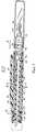
Шприц 20 (фиг.1) включает в себя карманный зажим 22 и имеет вид авторучки или механического карандаша. Шприц 20 включает в себя корпус 24 шприца, который содержит внутри контейнер 26 с жидкостью. Средство 28 иглы соединено с дальним концом 30 коpпуса 24 и содержит съемную защитную крышку 32. Накрывающий кожух 34 (показанный прозрачным на фиг.1) опоясывает корпус 24 шприца, средство 28 иглы и защитную крышку 32. The syringe 20 (FIG. 1) includes a
Влажный конец 36 накрывающего кожуха 34 соединен с дальним концом 38 манжеты 40. Манжета 40, показанная на фиг.2, выполнена унитарно с зажимом 22. Манжета 40 включает в себя внутреннюю резьбовую поверхность 42, которая навинчивается по резьбе на ближний конец 44 корпуса 24 шприца, тем самым создавая возможность относительного перемещения между корпусом 24 шприца и манжетой 40. Поршень 46 расположен внутри контейнера 26 с тем, чтобы выталкивать содержащуюся жидкость через иглу 48. The
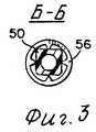
Шток 50 плунжера включает в себя дальний конец 52, который входит в контакт с поршнем 46 для приложения к поршню силы дозирования жидкости. Шток 52 плунжера показан на фиг.3 в поперечном сечении, как имеющий некруглую наружную конфигурацию. Стопор 54 закреплен в корпусе 24 шприца в фиксированном вращательном положении и включает в себя внутреннюю поверхность, имеющую конфигурацию, совпадающую с наружной поверхностью штока 50 плунжера, чтобы предотвращать относительное вращение между штоком 50 плунжера и корпусом 24 шприца. Толкающая шайба 56 проложена между стопором 54 и контейнером 26 и взаимодействует с поверхностью штока плунжера, как показано на фиг.3, чтобы предотвратить движение штока 50 плунжера в сторону от средства 28 иглы. Это обеспечивает условие, что для штока 50 плунжера возможно только одно движение, которое будет побуждать жидкость подвергаться дозированию из контейнера 26. Нижний конец 58 штока 50 плунжера включает в себя интегральный колпачок 60. Колпачок 60 имеет окно 62. Окно 62 лежит над элементом 64, который имеет на наружной поверхности рисунок индикации, образующий дозопоказывающую шкалу 66, как показано на фиг.4. Элемент 64 фрикционно взаимодействует с манжетой 40 и вообще перемещается с манжетой 40 относительно колпачка 60. The
При функционировании шприц 20 первоначально выглядит как показано на фиг.1. Для дозирования требуемого количества жидкости из шприца 20 накрывающий кожух 34 снимается со шприца телескопически вправо на фиг.1. Манжета 40 затем поворачивается в направлении стрелки А, тем самым вызывая перемещение манжеты 40 аксиально вправо. Когда это вращательное и аксиальное движение манжеты 40 происходит относительно корпуса 24 шприца, через взаимодействие внутренней резьбовой поверхности 42 и ближнего конца 44 корпуса шприца, колпачок 60 эффективно перемещается и путем вращения и движения аксиально в направлении стрелки В с сторону положения, показанного пунктиром в крайнем левом участке фиг.2. In operation, the
Когда происходит это перемещение, сегмент дозопоказывающей шкалы 66, который видим через окно 62, изменяется, тем самым показывает линейное увеличение чисел, показанных на фиг.4, для индикации увеличивающегося дозирования расходуемой жидкости. Требуемая доза тем самым может выбираться путем обозрения дозопоказывающей шкалы через окно 62. Следует также отметить, что манжета 40 может свободно вращаться в любом направлении, тем самым обеспечивая верхнюю и нижнюю регулировки дозирования, если требуемое дозирование было случайно пропущено во время действия регулирования. После того, как выбрано требуемое дозирование, защитная крышка 32 снимается со средства 28 иглы, а игла 48 располагается для соответствующей подкожной или внутримышечной инъекции жидкости, содержащейся в контейнере 26. После того, как игла 48 соответственно установлена, прилагается усадка к концу колпачка 60, вызывая линейное перемещение колпачка, интегрального штока 50 плунжера и поршня 46 в правую сторону для дозирования жидкости из контейнера 26. Дозирующее перемещение штока 50 плунжера останавливается из-за упорного контакта между колпачком 60 и элементом 64. После того, как требуемое количество жидкости дозировано из шприца 20, игла 48 выводится из положения инъекции, и защитный колпачок 32 устанавливается на место. Накрывающий кожух 34 также устанавливается на место. Наконец, элемент 64 может быть принудительно повернут относительно манжеты 40, пока в окне 62 не появится шкала "0". Следует отметить, что при каждом последующем использовании шприца 20 корпус 24 шприца отводится далее к манжете 40, что дает пользователю такого дозирующего шприца грубую визуальную индикацию количества жидкости, остающейся в шприце. When this movement occurs, the segment of the dose-indicating
Во втором предпочитаемом варианте реализации шприц 70, согласно изобретению, показанный на фиг.5, включает в себя карманный зажим 72, в остальном имеет общий внешний вид авторучки или механического карандаша. В шприце 70 карманный зажим 72 образован как часть накрывающего кожуха 74, который скользяще перемещается на принимающем его корпусе 76 шприца. Корпус 76 шприца включает в себя контейнер 78 жидкости, дозируемой через иглу 80 средства 82 иглы аналогично игле шприца 20. Контейнер 78 включает в себя поршень 86, который при перемещении вправо (на фиг.6) принуждает жидкость в контейнере 78 выталкиваться через иглу 80. In a second preferred embodiment, the
Шток 88 плунжера включает в себя дальний конец 90, входящий в контакт с поршнем 86. Шток 88 плунжера включает в себя спиральную наружную поверхность 92, прерываемую парой продольных каналов 94 и 96, которые лучше всего показаны на фиг.8 и 9. Корпус 76 шприца включает в себя пару выступающих внутрь пальцев 98 и 100, входящих в прорези или каналы 94 и 96 для предотвращения вращения штока 88 плунжера относительно корпуса 76 шприца. Нажимная гайка 102 (на фиг. 10) проложена между дальними поверхностями пальцев 98 и 100 и ближним концом контейнера 78. Внутрь выступающие шипы 104 на нажимной гайке 102 выступают в прорези или каналы 94 и 96 для вхождения в контакт с базой (основанием) каждого канала, предотвращая движение штока 88 плунжера в сторону от средства 82 иглы. The
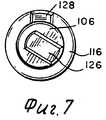
Полый колпачок 106 охватывает шток 88 плунжера и взаимодействует со спиральной поверхностью 92 штока 88 плунжера с помощью внутреннего резьбового участка 108 вблизи дальнего конца колпачка 106. Колпачок 106 включает в себя зубчатый снаружи участок 110, который взаимодействует с внутренним пальцем 112 корпуса 76 шприца для образования чувствительной вибрации в случае вращения колпачка 106 относительно корпуса 76 шприца. Наружный участок колпачка 114 имеет индикацию, образующую дозупоказывающую шкалу 116 (фиг.11). The
Манжета 118 смонтирована на корпусе 76 шприца с помощью стопора 120 и может вращаться относительно корпуса 76. Манжета охватывает всю выступающую часть 122 колпачка 106. Окно 24 в манжете 118 обеспечивает визуальное наблюдение ограниченного участка шкалы 116, имеющейся на наружном участке 114 колпачка 106. Колпачок 106 и манжета 118 содержит поверхностные средства 126 и 128 соответственно для зануления манжеты 118 относительно колпачка 106. The
При функционировании в целях использования шприца 70 для введения инъекции выбранного количества жидкости сначала вращается манжета 118 относительно корпуса 76 шприца до положения, при котором через окно 124 видна шкала двойного нуля, как показано на фиг.5. Манжета и колпачок выполнены таким образом, что это зануление шкалы 116 достигается автоматически путем вращения манжеты 118 относительно корпуса 76 шприца, пока поверхностные средства 126 и 128 не окажутся выравненными, как показано на фиг.5. When operating in order to use the
Выступающий участок 122 колпачка 106 затем поворачивается относительно корпуса 76 шприца. Это вращение колпачка 106 принуждает колпачок перемещаться по резьбе 92 штока 88 плунжера, тем самым перемещаясь аксиально влево, как показано на фиг.5 и 6. Вращение также принуждает участок шкалы 116, видимый через окно 124, изменяться, увеличивая числовые значения шкалы, как в первом варианте реализации. Вращение колпачка 106 относительно корпуса 76 шприца также принуждает палец 112 перемещаться (перепрыгивать) через пазы зубчатой поверхности 110, вызывая чувствительное движение пальца 112. Путем соблюдения соответственных размеров пазов число пазов, пересекаемых пальцем 112, может совпадать со шкалой, видимой через окно 124. Чувствительное движение гибкого пальца 112, соединяющего при начальном занулении, достигаемом путем совыравнивания поверхностных средств 125 и 128, дает возможность использовать шприц 70 лицу со слабым зрением. The protruding
В таком случае, когда шкала в отношении требуемой дозировки достигнута в окне 124, накрывающий кожух 74 может быть снят со шприца 70. Защитная крышка 84 может быть также снята с иглы 80, и игла соответственно установлена для инъекции. Затем прилагается давление к концу колпачка 106, принуждая его перемещаться аксиально со штоком 88 плунжера в сторону средства 82 иглы. Движение плунжерного штока принуждает поршень 86 выталкивать жидкость из жидкостного контейнера 78 через иглу 80. Движение колпачка 106 и плунжерного штока 88 прекращается из-за упора между колпачком 106 и корпусом 76 шприца в стопор 130. В течение этого осевого перемещения колпачка 106 выступающий палец 112 скользяще перемещается в одном пазу 110, тем самым ограничивая колпачок 106 от возможного вращательного движения относительно корпуса 76 шприца, что вызывало бы изменение выбранной дозы. In such a case, when the scale for the desired dosage is reached in the
После проведения инъекции выбранной дозы игла 80 удаляется из своего положения для инъекции, и защитная крышка 84 снова устанавливается на свое место, как показано на фиг.6. Накрывающий кожух затем снова устанавливается на свое место. За исключением, когда выбранная доза для инъекции была 20, 40 или 60 единиц шкалы, относительное положение между колпачком 106 и манжетой 118 будет другим, нежели выравненное положение, и будет выглядеть примерно таким, как показано на фиг.7. Манжета 118 может теперь вращаться относительно корпуса 76 шприца до нулевого положения, как описано ранее, так что шприц 70 готов для последующего выбора дозированного количества жидкости для инъекции. After injecting the selected dose, the
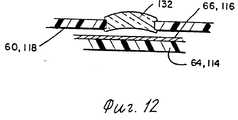
На фиг.12 показано в поперечном сечении окно любого варианта реализации, которое содержит линзу 132, которая действует для увеличения изображения дозопоказывающей шкалы. Хотя только второй иллюстрируемый вариант реализации включает в себя гибкий элемент 112, адаптированный для чувствительного движения в течение калиброванного регулирования шприца, такое же средство может быть включено в шприц 20. Хотя изобретение описано подробно со ссылкой на два иллюстрированных варианта реализации, другие изменения в модификации существуют в объеме и идее изобретения, и определены в формуле изобретения. 12 is a cross-sectional view of a window of any embodiment that includes a
Claims (5)
Translated fromRussianApplications Claiming Priority (2)
| Application Number | Priority Date | Filing Date | Title |
|---|---|---|---|
| US504254 | 1990-04-04 | ||
| US07/504,254US5226896A (en) | 1990-04-04 | 1990-04-04 | Dose indicating injection pen |
Publications (1)
| Publication Number | Publication Date |
|---|---|
| RU2033193C1true RU2033193C1 (en) | 1995-04-20 |
Family
ID=24005496
Family Applications (1)
| Application Number | Title | Priority Date | Filing Date |
|---|---|---|---|
| SU914895034ARU2033193C1 (en) | 1990-04-04 | 1991-04-03 | Device for performance of injections |
Country Status (23)
| Country | Link |
|---|---|
| US (2) | US5226896A (en) |
| EP (1) | EP0450905B1 (en) |
| JP (1) | JPH066159B2 (en) |
| KR (1) | KR960000846B1 (en) |
| AR (1) | AR245371A1 (en) |
| AT (1) | ATE129162T1 (en) |
| AU (1) | AU639542B2 (en) |
| CA (1) | CA2039471C (en) |
| DE (1) | DE69113847T2 (en) |
| DK (1) | DK0450905T3 (en) |
| ES (1) | ES2079565T3 (en) |
| FI (1) | FI104235B1 (en) |
| GR (1) | GR3017999T3 (en) |
| HU (1) | HU210293B (en) |
| IE (1) | IE69664B1 (en) |
| IL (1) | IL97683A (en) |
| MX (1) | MX173301B (en) |
| NO (1) | NO300306B1 (en) |
| NZ (1) | NZ237622A (en) |
| PT (1) | PT97248B (en) |
| RU (1) | RU2033193C1 (en) |
| YU (1) | YU47961B (en) |
| ZA (1) | ZA912399B (en) |
Cited By (7)
| Publication number | Priority date | Publication date | Assignee | Title |
|---|---|---|---|---|
| RU2234882C1 (en)* | 2003-01-30 | 2004-08-27 | Рисованная Ольга Николаевна | Injection device |
| RU2268753C2 (en)* | 2001-07-30 | 2006-01-27 | Текфарма Лайсензинг Аг | Locking unit for coupling body sections of injection device |
| RU2270035C2 (en)* | 2001-07-30 | 2006-02-20 | Текфарма Лайсензинг Аг | Injection apparatus comprising rotation preventing unit |
| RU2277939C2 (en)* | 2000-09-27 | 2006-06-20 | Шеринг Акциенгезельшафт | Syringe having cylinder fillable with liquid and closing cap |
| RU2283142C2 (en)* | 2001-07-30 | 2006-09-10 | Текфарма Лайсензинг Аг | Reservoir module provided with piston rod |
| RU2288745C2 (en)* | 2002-07-16 | 2006-12-10 | Текфарма Лайсензинг Аг | Device for introducing fluid product |
| RU2316388C2 (en)* | 2002-06-28 | 2008-02-10 | Асепт Медикал Аб | Device for mixing and supplying cement |
Families Citing this family (190)
| Publication number | Priority date | Publication date | Assignee | Title |
|---|---|---|---|---|
| FR2671729A1 (en)* | 1991-01-17 | 1992-07-24 | Micro Dose Pharma | DEVICE FOR DELIVERING CONTROLLED DOSES, PARTICULARLY OF THE DISPOSABLE INSULIN SYRINGE TYPE. |
| US5298023A (en)* | 1991-03-08 | 1994-03-29 | Habley Medical Technology Corporation | Multiple pharmaceutical dispenser with accumulator |
| DE4112259A1 (en)* | 1991-04-15 | 1992-10-22 | Medico Dev Investment Co | INJECTION DEVICE |
| DK134691D0 (en)* | 1991-07-12 | 1991-07-12 | Novo Nordisk As | APPARATUS |
| DK175491D0 (en) | 1991-10-18 | 1991-10-18 | Novo Nordisk As | APPARATUS |
| SE9103215D0 (en)* | 1991-11-04 | 1991-11-04 | Kabi Pharmacia Ab | A METHOD AND DEVICE FOR DOSING A LIQUID PREPARATION |
| US5328486A (en)* | 1991-11-19 | 1994-07-12 | American Cyanamid Company | Syringe for dispensing multiple dosages |
| DK194291D0 (en)* | 1991-11-29 | 1991-11-29 | Novo Nordisk As | SPRAY FOR AUTOMATIC INJECTION. |
| FR2684880B1 (en)* | 1991-12-17 | 1994-03-25 | Micro Dose Pharma | MECHANICAL DEVICE WITH DISPLAY OF A VISUAL INDICATION, SUCH AS A GRADUATION. |
| CH682806A5 (en)* | 1992-02-21 | 1993-11-30 | Medimpex Ets | Injection device. |
| CH682805A5 (en)* | 1992-02-24 | 1993-11-30 | Medimpex Ets | Display device for an injection device. |
| GB9219849D0 (en)* | 1992-09-19 | 1992-10-28 | Hypoguard Uk Ltd | Device |
| US5391157A (en)* | 1992-10-20 | 1995-02-21 | Eli Lilly And Company | End of dose indicator |
| US5545147A (en)* | 1992-10-20 | 1996-08-13 | Eli Lilly And Company | Anti-backup improvement for hypodermic syringes |
| US5378233A (en)* | 1992-11-18 | 1995-01-03 | Habley Medical Technology Corporation | Selected dose pharmaceutical dispenser |
| US5584815A (en)* | 1993-04-02 | 1996-12-17 | Eli Lilly And Company | Multi-cartridge medication injection device |
| US5472022A (en)* | 1993-11-02 | 1995-12-05 | Genentech, Inc. | Injection pen solution transfer apparatus and method |
| ES2070782B1 (en)* | 1993-11-05 | 1995-12-16 | Vita Invest Sa | IMPROVEMENTS IN SELF-INJECTABLE EQUIPMENT. |
| US5514097A (en)* | 1994-02-14 | 1996-05-07 | Genentech, Inc. | Self administered injection pen apparatus and method |
| US5536249A (en)* | 1994-03-09 | 1996-07-16 | Visionary Medical Products, Inc. | Pen-type injector with a microprocessor and blood characteristic monitor |
| US5725508A (en)* | 1994-06-22 | 1998-03-10 | Becton Dickinson And Company | Quick connect medication delivery pen |
| CA2154853C (en) | 1994-07-27 | 2007-01-16 | John Glyndwr Wilmot | Nipple plunger |
| JP3568959B2 (en)* | 1995-03-07 | 2004-09-22 | イーライ・リリー・アンド・カンパニー | Reusable dosing device |
| US5651775A (en) | 1995-07-12 | 1997-07-29 | Walker; Richard Bradley | Medication delivery and monitoring system and methods |
| AU1860697A (en)* | 1995-09-08 | 1997-07-28 | Visionary Medical Products Corporation | Pen-type injector drive mechanism |
| US5776103A (en) | 1995-10-11 | 1998-07-07 | Science Incorporated | Fluid delivery device with bolus injection site |
| US5658259A (en)* | 1995-10-19 | 1997-08-19 | Meridian Medical Technologies, Inc. | Dental cartridge assembly auto-injector with protective needle cover |
| US5741242A (en)* | 1995-12-22 | 1998-04-21 | Science Incorporated | Infusion device with fill assembly |
| DK0831947T3 (en) | 1996-04-02 | 2002-12-23 | Disetronic Licensing Ag | injector |
| WO1997036626A1 (en)* | 1996-04-02 | 1997-10-09 | Disetronic Licensing Ag | Injection device |
| US6413242B1 (en) | 1996-07-05 | 2002-07-02 | Disetronic Licensing Ag | Injection device for injection of liquid |
| DE59611288D1 (en)* | 1996-07-05 | 2005-12-01 | Tecpharma Licensing Ag | INJECTION DEVICE FOR INJECTING LIQUID |
| US6146361A (en)* | 1996-09-26 | 2000-11-14 | Becton Dickinson And Company | Medication delivery pen having a 31 gauge needle |
| DE29703820U1 (en)* | 1997-03-03 | 1998-07-02 | Medico Development Investment Co., Ascona | Injection device |
| DE19717107B4 (en) | 1997-04-23 | 2005-06-23 | Disetronic Licensing Ag | System of container and drive device for a piston, which is held in the container containing a drug fluid |
| EP1841271B1 (en)* | 1997-04-24 | 2017-11-08 | Ntt Docomo, Inc. | Mobile station and network controller |
| DE19723647C1 (en) | 1997-06-05 | 1998-12-24 | Disetronic Licensing Ag | Fluid dosing unit indicator for e.g. insulin or for pipetting laboratory fluids |
| TW533865U (en) | 1997-06-10 | 2003-05-21 | Glaxo Group Ltd | Dispenser for dispensing medicament and actuation indicating device |
| DE19740187C1 (en)* | 1997-09-12 | 1999-04-15 | Disetronic Licensing Ag | Dosing unit, e.g. for medicines |
| ES2140328B1 (en)* | 1997-12-04 | 2000-10-16 | Perez Jose Manuel Prieto | APPLICATOR DEVICE FOR AMPOULES OF INJECTABLE THERAPEUTIC SUBSTANCES. |
| DE19755125B4 (en) | 1997-12-11 | 2006-04-20 | Tecpharma Licensing Ag | Needle protection device for injection devices |
| CZ297361B6 (en)* | 1998-01-30 | 2006-11-15 | Novo Nordisk A/S | Injection syringe |
| US6001082A (en)* | 1998-02-20 | 1999-12-14 | Becton Dickinson And Company | Medication delivery pen with an integral magnifying pocket clip |
| US6126637A (en)* | 1998-04-15 | 2000-10-03 | Science Incorporated | Fluid delivery device with collapsible needle cover |
| DE19822031C2 (en) | 1998-05-15 | 2000-03-23 | Disetronic Licensing Ag | Auto injection device |
| DE19821933C1 (en)* | 1998-05-15 | 1999-11-11 | Disetronic Licensing Ag | Device for administering an injectable product |
| US6290679B1 (en) | 1999-05-14 | 2001-09-18 | Disetronic Licensing Ag | Device for metered administration of an injectable product |
| US6689108B2 (en)* | 1998-11-13 | 2004-02-10 | Elan Pharma International Limited | Device for measuring a volume of drug |
| RU2154501C1 (en)* | 1998-11-20 | 2000-08-20 | Григорьянц Рубен Исаакович | Syringe for implanting tissues into subcutaneous cellulose |
| US20040069044A1 (en)* | 1999-04-29 | 2004-04-15 | Gilad Lavi | Device for measuring a volume of drug |
| DE19945397C2 (en)* | 1999-09-22 | 2001-07-19 | Disetronic Licensing Ag | Device for the dosed administration of an injectable product |
| USD449687S1 (en) | 2000-08-31 | 2001-10-23 | Disetronic Licensing Ag | Needle shield for an injection device |
| US6547763B2 (en) | 2000-05-18 | 2003-04-15 | Novo Nordisk A/S | Dose display for injection device |
| US6663602B2 (en) | 2000-06-16 | 2003-12-16 | Novo Nordisk A/S | Injection device |
| US6986760B2 (en)* | 2000-08-02 | 2006-01-17 | Becton, Dickinson And Company | Pen needle and safety shield system |
| EP3138598B1 (en)* | 2000-08-02 | 2019-10-23 | Becton, Dickinson and Company | Pen needle and safety shield system |
| CN1268405C (en)* | 2000-10-09 | 2006-08-09 | 伊莱利利公司 | Pen device for administration of parathyroid hormone |
| US6899699B2 (en)* | 2001-01-05 | 2005-05-31 | Novo Nordisk A/S | Automatic injection device with reset feature |
| US6673049B2 (en) | 2001-02-15 | 2004-01-06 | Disetronic Licensing Ag | Injection device for injecting fluid |
| SE518708C2 (en)* | 2001-02-28 | 2002-11-12 | Mats Bonniers Sjukvaard Och Ut | Syringe with metering device |
| JP2004529754A (en) | 2001-03-14 | 2004-09-30 | ペンジェット・コーポレーション | System and method for removing dissolved gases from a solution |
| US20050192530A1 (en)* | 2001-04-13 | 2005-09-01 | Penjet Corporation | Method and apparatus for needle-less injection with a degassed fluid |
| US6613010B2 (en) | 2001-04-13 | 2003-09-02 | Penjet Corporation | Modular gas-pressured needle-less injector |
| EP1427463A2 (en) | 2001-04-27 | 2004-06-16 | PenJet Corporation | Method and apparatus for filling or refilling a needle-less injector |
| USD462760S1 (en) | 2001-06-13 | 2002-09-10 | Eli Lilly And Company | Medication delivery apparatus |
| DE10163326A1 (en)* | 2001-07-30 | 2003-02-27 | Disetronic Licensing Ag | Administration device with dosing device |
| DE20112501U1 (en)* | 2001-07-30 | 2002-12-19 | Disetronic Licensing Ag, Burgdorf | Locking lock for connecting housing parts of an injection or infusion device |
| ATE333260T1 (en) | 2001-08-27 | 2006-08-15 | Novo Nordisk As | A CARTRIDGE AND A MEDICAL DELIVERY SYSTEM THAT ACCOMMODATE SUCH A CARTRIDGE |
| US20040098010A1 (en)* | 2001-10-22 | 2004-05-20 | Glenn Davison | Confuser crown skin pricker |
| US6824526B2 (en) | 2001-10-22 | 2004-11-30 | Penjet Corporation | Engine and diffuser for use with a needle-less injector |
| DE20209051U1 (en)* | 2001-12-21 | 2003-04-24 | Disetronic Licensing Ag, Burgdorf | Medicament administration device has dosage adjuster mounted on piston rod and end stop mounted at end of its path, locking system preventing adjuster from rotating and pressing against stop |
| GB0205485D0 (en)* | 2002-03-08 | 2002-04-24 | Dca Design Int Ltd | Improvements in and relating to a medicament delivery service |
| DE10229138B4 (en)* | 2002-06-28 | 2008-01-31 | Tecpharma Licensing Ag | Product diverter with piston rod emergency reset |
| DE10232412A1 (en)* | 2002-07-17 | 2004-02-05 | Disetronic Licensing Ag | Administration device with priming function |
| JP4448448B2 (en)* | 2002-09-24 | 2010-04-07 | エス・ホー・エル・グループ・アクチボラゲット | Injection device |
| US7018356B2 (en) | 2002-10-31 | 2006-03-28 | Wise Roger R | Method and apparatus for adjusting the contents of a needle-less injector |
| US6896666B2 (en)* | 2002-11-08 | 2005-05-24 | Kochamba Family Trust | Cutaneous injection delivery under suction |
| US20060264926A1 (en)* | 2002-11-08 | 2006-11-23 | Kochamba Gary S | Cutaneous stabilization by vacuum for delivery of micro-needle array |
| EP2210634A1 (en)* | 2009-01-22 | 2010-07-28 | Sanofi-Aventis Deutschland GmbH | Drug delivery device dose setting mechanism |
| GB0304822D0 (en) | 2003-03-03 | 2003-04-09 | Dca Internat Ltd | Improvements in and relating to a pen-type injector |
| GB0304823D0 (en) | 2003-03-03 | 2003-04-09 | Dca Internat Ltd | Improvements in and relating to a pen-type injector |
| DE10327119A1 (en) | 2003-06-13 | 2004-12-30 | Aventis Pharma Deutschland Gmbh | Injection cap |
| US8932264B2 (en)* | 2003-08-11 | 2015-01-13 | Becton, Dickinson And Company | Medication delivery pen assembly with needle locking safety shield |
| DE20317377U1 (en)* | 2003-11-03 | 2005-03-17 | B D Medico S A R L | injection device |
| US7293803B2 (en)* | 2003-12-16 | 2007-11-13 | Ching-Nan Chu | Method for indicating the user's name on a blood-sampling needle pen and the product thereof |
| MX2007003682A (en) | 2004-10-04 | 2007-08-07 | Sanofi Aventis Deutschland | Drive mechanism for a drug delivery device. |
| KR101278123B1 (en) | 2004-10-21 | 2013-06-24 | 노보 노르디스크 에이/에스 | Injection device with torsion spring and rotatable display |
| ATE444090T1 (en) | 2004-10-21 | 2009-10-15 | Novo Nordisk As | SELECTION MECHANISM FOR A ROTARY PIN |
| US20090043264A1 (en) | 2005-04-24 | 2009-02-12 | Novo Nordisk A/S | Injection Device |
| US20070113861A1 (en)* | 2005-11-08 | 2007-05-24 | Novo Nordisk A/S | Cap for a medical device |
| JP4834389B2 (en)* | 2005-11-29 | 2011-12-14 | 前田産業株式会社 | Injection device |
| GB0524604D0 (en)* | 2005-12-02 | 2006-01-11 | Owen Mumford Ltd | Injection method and apparatus |
| US20080269688A1 (en)* | 2005-12-08 | 2008-10-30 | Jose Colucci | Dose Indicating Assembly of a Pharmaceutical Injection Device |
| GB2434103B (en)* | 2006-01-12 | 2009-11-25 | Owen Mumford Ltd | Lancet firing device |
| CN101400394B (en)* | 2006-03-10 | 2012-07-04 | 诺沃-诺迪斯克有限公司 | An injection device having a gearing arrangement |
| JP5062768B2 (en)* | 2006-03-10 | 2012-10-31 | ノボ・ノルデイスク・エー/エス | INJECTION DEVICE AND METHOD FOR REPLACING CARTRIDGE OF THE DEVICE |
| ATE458517T1 (en) | 2006-05-16 | 2010-03-15 | Novo Nordisk As | TRANSMISSION MECHANISM FOR AN INJECTION DEVICE |
| JP5253387B2 (en) | 2006-05-18 | 2013-07-31 | ノボ・ノルデイスク・エー/エス | Injection device with mode locking means |
| EP2037987B1 (en) | 2006-06-30 | 2019-09-04 | Novo Nordisk A/S | A medical delivery system comprising a coding mechanism |
| DE502006008281D1 (en)* | 2006-07-14 | 2010-12-23 | Roche Diagnostics Gmbh | Injection device with a second device function for obtaining a body fluid sample |
| EP2043708B1 (en)* | 2006-07-15 | 2010-12-29 | Novo Nordisk A/S | Medical delivery system with asymmetrical coding means |
| JP2009543630A (en)* | 2006-07-15 | 2009-12-10 | ノボ・ノルデイスク・エー/エス | Drug delivery system with rotatable coding element |
| ATE493162T1 (en)* | 2006-08-28 | 2011-01-15 | Novo Nordisk As | AXIAL LOCKABLE AND ROTATION OPEN MEDICATION ADMINISTRATION SYSTEM |
| US20080077430A1 (en)* | 2006-09-25 | 2008-03-27 | Singer Michael S | Systems and methods for improving medication adherence |
| EP2083888A1 (en)* | 2006-11-17 | 2009-08-05 | Novo Nordisk A/S | A medical delivery system comprising a coding mechanism between dosing assembly and medicament container |
| ATE507863T1 (en)* | 2006-11-21 | 2011-05-15 | Novo Nordisk As | MEDICAL DISPENSING SYSTEM HAVING A LOCKING RING WITH L-SHAPED GROOVES |
| EP2091598B1 (en)* | 2006-12-15 | 2012-07-11 | Novo Nordisk A/S | A medical delivery system comprising a container and a dosing assembly with radially moving fastening means |
| WO2008074897A1 (en)* | 2006-12-21 | 2008-06-26 | Novo Nordisk A/S | A syringe device |
| CA2712040A1 (en)* | 2007-01-12 | 2008-07-24 | Healthhonors Corporation | Behavior modification with intermittent reward |
| EP2109474B2 (en) | 2007-02-05 | 2019-01-30 | Novo Nordisk A/S | Injection button |
| CA121972S (en)* | 2007-02-23 | 2008-11-25 | Sanofi Aventis Deutschland | Medical injector |
| BRPI0809265A2 (en) | 2007-03-23 | 2014-10-07 | Novo Nordisk As | INJECTION DEVICE INCLUDING A TIGHTENING NUT |
| DE102007018696A1 (en) | 2007-04-18 | 2008-10-23 | Sanofi-Aventis Deutschland Gmbh | Injection device for dispensing a medicament |
| US8986253B2 (en) | 2008-01-25 | 2015-03-24 | Tandem Diabetes Care, Inc. | Two chamber pumps and related methods |
| US8172813B2 (en)* | 2008-02-28 | 2012-05-08 | Becton, Dickinson And Company | Syringe with two piece plunger rod |
| US7976510B2 (en)* | 2008-02-28 | 2011-07-12 | Becton, Dickinson And Company | Syringe with adjustable two piece plunger rod |
| JP2009240411A (en) | 2008-03-28 | 2009-10-22 | Terumo Corp | Drug container |
| RU2496528C2 (en) | 2008-05-02 | 2013-10-27 | Санофи-Авентис Дойчланд Гмбх | Drug feeder |
| EP2310073B1 (en)* | 2008-07-09 | 2012-10-24 | Sanofi-Aventis Deutschland GmbH | Medication delivery device and method of assembling a medication delivery device |
| USD641077S1 (en) | 2008-09-15 | 2011-07-05 | Sanofi-Aventis Deutschland Gmbh | Medical injector |
| EP2326370B1 (en)* | 2008-09-18 | 2020-08-05 | Becton, Dickinson and Company | Medical injector with slidable sleeve activation |
| USD651305S1 (en) | 2008-10-11 | 2011-12-27 | Sanofi-Aventis Deutschland Gmbh | Medical injector |
| CA130178S (en) | 2008-10-11 | 2010-08-25 | Sanofi Aventis Deutschland | Medical injector |
| PT2468344E (en) | 2008-10-13 | 2013-10-14 | Sanofi Aventis Deutschland | Drug delivery device and method of manufacturing a drug delivery device |
| GB2465390A (en) | 2008-11-17 | 2010-05-19 | Owen Mumford Ltd | Syringe needle cover remover |
| EP2196233A1 (en) | 2008-12-12 | 2010-06-16 | Sanofi-Aventis Deutschland GmbH | Resettable drive mechanism for a medication delivery device and medication delivery device |
| US10987473B2 (en)* | 2009-02-06 | 2021-04-27 | Becton, Dickinson And Company | Lubricated pen needle |
| US9526840B2 (en) | 2009-03-31 | 2016-12-27 | Sanofi-Aventis Deutschland Gmbh | Drug delivery device |
| WO2010112558A1 (en)* | 2009-03-31 | 2010-10-07 | Sanofi-Aventis Deutschland Gmbh | Drug delivery device with dose indication window |
| WO2010112565A1 (en) | 2009-03-31 | 2010-10-07 | Sanofi-Aventis Deutschland Gmbh | Dose button for a drug delivery device and method for manufacturing a dose button |
| WO2010115821A1 (en) | 2009-03-31 | 2010-10-14 | Sanofi-Aventis Deutschland Gmbh | Pen cap |
| WO2010115820A1 (en) | 2009-03-31 | 2010-10-14 | Sanofi-Aventis Deutschland Gmbh | Method for manufacturing a drug delivery device body using an adhesive and drug delivery device body |
| RU2530661C2 (en) | 2009-04-30 | 2014-10-10 | Санофи-Авентис Дойчланд Гмбх | Axially regulated connection of piston rod with piston for drive mechanism of device for medicinal substance delivery |
| US8672896B2 (en)* | 2009-06-01 | 2014-03-18 | Sanofi-Aventis Deutschland Gmbh | Inner housing for a drug delivery device |
| US8257319B2 (en) | 2009-06-01 | 2012-09-04 | Sanofi-Aventis Deutschland Gmbh | Drug delivery device inner housing having helical spline |
| US10034982B2 (en) | 2009-06-01 | 2018-07-31 | Sanofi-Aventis Deutschland Gmbh | Spindle for a drug delivery device |
| TWI530306B (en) | 2009-06-02 | 2016-04-21 | 賽諾菲阿凡提斯德意志有限公司 | Drug delivery device assembly and drug delivery device |
| EP2724739B1 (en) | 2009-07-30 | 2015-07-01 | Tandem Diabetes Care, Inc. | Portable infusion pump system |
| WO2011039213A2 (en)* | 2009-09-30 | 2011-04-07 | Sanofi-Aventis Deutschland Gmbh | An assembly of a drug delivery device |
| EP2482901B1 (en) | 2009-09-30 | 2019-10-23 | Sanofi-Aventis Deutschland GmbH | Injection device |
| GB0918145D0 (en) | 2009-10-16 | 2009-12-02 | Owen Mumford Ltd | Injector apparatus |
| PL215310B1 (en) | 2009-10-30 | 2013-11-29 | Kappa Medilab Spolka Z Ograniczona Odpowiedzialnoscia | Automatic applicator, especially for insulin |
| EP2496290B1 (en) | 2009-11-03 | 2017-01-04 | Sanofi-Aventis Deutschland GmbH | Assembly for a drug delivery device and drug delivery device |
| EP2506900A1 (en)* | 2009-12-02 | 2012-10-10 | Sanofi-Aventis Deutschland GmbH | Dose display mechanism for a drug delivery device |
| USD685464S1 (en) | 2010-01-11 | 2013-07-02 | Sanofi-Aventis Deutschland Gmbh | Medical injector |
| GB201004626D0 (en) | 2010-03-19 | 2010-05-05 | Owen Mumford Ltd | Improved injection device |
| CA3042909C (en) | 2010-06-18 | 2021-04-13 | Becton, Dickinson And Company | Adjustable dose setting plunger for syringe |
| WO2012017035A1 (en) | 2010-08-06 | 2012-02-09 | Sanofi-Aventis Deutschland Gmbh | Cartridge holder and method for assembling a cartridge unit for a drug delivery device |
| MX349452B (en)* | 2010-10-25 | 2017-07-31 | Sanofi Aventis Deutschland | Drug delivery device and method for assembling a drug delivery device. |
| TWI538707B (en) | 2011-05-06 | 2016-06-21 | 賽諾菲阿凡提斯德意志有限公司 | Drug delivery device and cartridge holder for a drug delivery device |
| JP6069351B2 (en) | 2011-12-29 | 2017-02-01 | ノボ・ノルデイスク・エー/エス | Torsion spring type automatic syringe with dial-up / dial-down administration mechanism |
| MX360468B (en)* | 2012-04-05 | 2018-11-05 | Sanofi Aventis Deutschland | Pen -type injector with window element. |
| DK2838591T3 (en) | 2012-04-19 | 2023-02-06 | Sanofi Aventis Deutschland | DEVICE FOR A DRUG ADMINISTRATION DEVICE AND DRUG ADMINISTRATION DEVICE |
| US9180242B2 (en) | 2012-05-17 | 2015-11-10 | Tandem Diabetes Care, Inc. | Methods and devices for multiple fluid transfer |
| WO2013178600A1 (en) | 2012-05-30 | 2013-12-05 | Sanofi-Aventis Deutschland Gmbh | Bearing for a piston rod body for a drug delivery device, a piston rod arrangement and a piston rod body |
| US9555186B2 (en) | 2012-06-05 | 2017-01-31 | Tandem Diabetes Care, Inc. | Infusion pump system with disposable cartridge having pressure venting and pressure feedback |
| WO2014005807A1 (en)* | 2012-07-06 | 2014-01-09 | Carebay Europe Ltd | Medicament delivery device |
| WO2014023771A1 (en) | 2012-08-08 | 2014-02-13 | Sanofi-Aventis Deutschland Gmbh | Drug delivery device with tamper-evident closure |
| WO2014033197A1 (en) | 2012-08-31 | 2014-03-06 | Sanofi-Aventis Deutschland Gmbh | Drug delivery device |
| SG11201500322TA (en) | 2012-08-31 | 2015-02-27 | Sanofi Aventis Deutschland | Drug delivery device |
| WO2014040929A1 (en) | 2012-09-11 | 2014-03-20 | Sanofi-Aventis Deutschland Gmbh | Drive mechanism for a drug delivery device and drug delivery device |
| BR112015010607A2 (en) | 2012-11-09 | 2017-12-05 | Iinjec Tech Inc | fluid delivery injector, retractable needle assembly, and method for injecting at least one dose of a transcutaneously fluid medication into the body. |
| TWI653069B (en) | 2013-03-11 | 2019-03-11 | 德商賽諾菲阿凡提斯德意志有限公司 | "piston rod and drug delivery device comprising the piston rod" |
| DK2968783T3 (en) | 2013-03-13 | 2021-07-12 | Sanofi Aventis Deutschland | MEDICINE DELIVERY DEVICE WITH A FEEDBACK FUNCTION |
| JP6480350B2 (en) | 2013-03-13 | 2019-03-06 | サノフィ−アベンティス・ドイチュラント・ゲゼルシャフト・ミット・ベシュレンクテル・ハフツング | Assembly of drug delivery device including feedback function |
| DK2968774T3 (en)* | 2013-03-13 | 2019-07-15 | Sanofi Aventis Deutschland | PHARMACEUTICAL INJECTION DEVICE WITH OPTICAL WINDOW ELEMENTS FOR CLEAR READING A DOSE VALUE |
| US9173998B2 (en) | 2013-03-14 | 2015-11-03 | Tandem Diabetes Care, Inc. | System and method for detecting occlusions in an infusion pump |
| US9180243B2 (en) | 2013-03-15 | 2015-11-10 | Tandem Diabetes Care, Inc. | Detection of infusion pump conditions |
| DK2978470T3 (en)* | 2013-03-28 | 2021-07-26 | Sanofi Aventis Deutschland | FILLING DEVICE FOR A MEDICINE DELIVERY DEVICE AND SYSTEM WITH A FILLING DEVICE AND A MEDICINE DELIVERY DEVICE |
| US10232118B2 (en) | 2013-04-10 | 2019-03-19 | Sanofi | Drive assembly for a drug delivery device |
| RU2669469C2 (en) | 2013-05-16 | 2018-10-11 | Санофи-Авентис Дойчланд Гмбх | Mechanism for drug delivery device |
| WO2014191190A1 (en) | 2013-05-27 | 2014-12-04 | Sanofi-Aventis Deutschland Gmbh | Drive assembly for a drug delivery device and drug delivery device |
| US10668218B2 (en) | 2013-08-29 | 2020-06-02 | Sanofi-Aventis Deutschland Gmbh | Housing and cap for an injection device made of an outer metal part and an inner plastic part |
| EP3038678B1 (en) | 2013-08-29 | 2020-01-01 | Sanofi-Aventis Deutschland GmbH | Cap for a drug delivery device |
| EP3038679B1 (en) | 2013-08-29 | 2021-05-05 | Sanofi-Aventis Deutschland GmbH | Cap assembly for a drug delivery device and drug delivery device |
| WO2015032783A1 (en) | 2013-09-03 | 2015-03-12 | Sanofi | Drive mechanism and injection device herewith |
| RU2680922C2 (en) | 2013-09-23 | 2019-02-28 | Санофи-Авентис Дойчланд Гмбх | Assembly for drug delivery device and drug delivery device |
| KR200475972Y1 (en)* | 2013-10-02 | 2015-01-21 | (주)아모레퍼시픽 | A Cosmetic Liquid Syringe |
| WO2015091763A1 (en) | 2013-12-20 | 2015-06-25 | Sanofi-Aventis Deutschland Gmbh | Assembly for a drug delivery device and drug delivery device |
| USD770038S1 (en) | 2014-06-26 | 2016-10-25 | Eli Lilly And Company | Medication injection device |
| CA3009221A1 (en) | 2014-12-23 | 2016-06-30 | Automed Pty Ltd | Delivery apparatus, system and associated methods |
| EP3064239A1 (en)* | 2015-03-05 | 2016-09-07 | Carebay Europe Ltd. | Medicament delivery device with information provider system |
| US11400218B2 (en) | 2015-03-23 | 2022-08-02 | Sanofi-Aventis Deutschland Gmbh | Housing for an injection device and interconnection of housing components |
| PL414382A1 (en) | 2015-10-15 | 2017-04-24 | Copernicus Spółka Z Ograniczoną Odpowiedzialnością | Setting mechanism, in particular for dosing |
| US11400228B2 (en)* | 2015-12-30 | 2022-08-02 | Shl Medical Ag | Medicament delivery device |
| JP6969876B2 (en) | 2016-02-29 | 2021-11-24 | メディセル・アーゲー | Transmission mechanism, especially injectors with gear trains |
| EP3348294A1 (en) | 2017-01-13 | 2018-07-18 | Carebay Europe Ltd. | Medicament delivery device |
| RS65380B1 (en) | 2017-08-24 | 2024-04-30 | Novo Nordisk As | Glp-1 compositions and uses thereof |
| IL294520A (en) | 2020-02-18 | 2022-09-01 | Novo Nordisk As | Pharmaceutical formulations |
| US11957542B2 (en) | 2020-04-30 | 2024-04-16 | Automed Patent Holdco, Llc | Sensing complete injection for animal injection device |
Family Cites Families (22)
| Publication number | Priority date | Publication date | Assignee | Title |
|---|---|---|---|---|
| US3232117A (en)* | 1962-09-14 | 1966-02-01 | Roger Gilmont Instr Inc | Micrometer buret |
| DE1632032B2 (en)* | 1967-12-20 | 1977-11-03 | Fa Rudolf Brand, 6980 Wertheim | INSTRUMENT FOR PROMOTING AND VARIABLE PRE-SELECTABLE DOSING OF LIQUIDS |
| US3613952A (en)* | 1970-04-23 | 1971-10-19 | Cole Parmer Instr Co | Fluid dispenser with adjustable stroke piston and register |
| US3815785A (en)* | 1972-12-04 | 1974-06-11 | Gilmont R Instr Inc | Micrometric dispenser with calibration means |
| US4096751A (en)* | 1977-06-15 | 1978-06-27 | Oxford Laboratories Inc. | Hand-held micropipettor with fluid transfer volume adjustment mechanism |
| DE3163728D1 (en)* | 1980-04-08 | 1984-06-28 | Greater Glasgow Health Board | Dispensing device |
| DE3031830C2 (en)* | 1980-08-23 | 1983-02-17 | Witeg-Glasgeräte Helmut Antlinger KG, 6980 Wertheim | Bottle dispenser |
| IE52621B1 (en)* | 1981-02-12 | 1988-01-06 | Turner Robert Charles | Dose metering plunger devices for use with syringes |
| US4367739A (en)* | 1981-04-20 | 1983-01-11 | Leveen Harry H | Syringe |
| US4395921A (en)* | 1981-06-26 | 1983-08-02 | Scientific Manufacturing Industries, Inc. | Adjustable volume liquid dispenser |
| US4475905A (en)* | 1982-09-30 | 1984-10-09 | Himmelstrup Anders B | Injection device |
| US4592745A (en)* | 1984-02-29 | 1986-06-03 | Novo Industri A/S | Dispenser |
| WO1987002895A1 (en)* | 1985-11-08 | 1987-05-21 | Disetronic Ag | Injection instrument |
| DE3638984C3 (en)* | 1986-11-14 | 1993-11-18 | Haselmeier Wilhelm Fa | Injection device |
| DK177187A (en)* | 1987-04-07 | 1988-10-08 | Dcp Af 1988 As | DOSING UNIT FOR DOSING A NUMBER OF MEASURED QUANTITIES OF A FLUID, SUCH AS INSULIN, FROM A GLASS AMPULA |
| DE3715258C2 (en)* | 1987-05-08 | 1996-10-31 | Haselmeier Wilhelm Fa | Injection device |
| GB8713810D0 (en)* | 1987-06-12 | 1987-07-15 | Hypoguard Uk Ltd | Measured dose dispensing device |
| CH675078A5 (en)* | 1988-01-22 | 1990-08-31 | Nosta Ag | |
| DK166948B1 (en)* | 1988-02-10 | 1993-08-09 | Dcp Af 1988 As | DOSING UNIT FOR DOSING A NUMBER OF MEASURED QUANTITIES OF A FLUID, SUCH AS INSULIN, FROM A GLASS STUBLE |
| US4973318A (en)* | 1988-02-10 | 1990-11-27 | D.C.P. Af 1988 A/S | Disposable syringe |
| GB8809115D0 (en)* | 1988-04-18 | 1988-05-18 | Turner R C | Syringes |
| US5244465A (en)* | 1988-10-19 | 1993-09-14 | Byk Gulden Lomberg Chemische Fabrik Gmbh | Reusable injection device for distributing a preselected dose |
- 1990
- 1990-04-04USUS07/504,254patent/US5226896A/ennot_activeExpired - Lifetime
- 1991
- 1991-03-20NONO911115Apatent/NO300306B1/ennot_activeIP Right Cessation
- 1991-03-26ILIL9768391Apatent/IL97683A/ennot_activeIP Right Cessation
- 1991-03-28CACA002039471Apatent/CA2039471C/ennot_activeExpired - Fee Related
- 1991-03-28NZNZ237622Apatent/NZ237622A/enunknown
- 1991-03-28ZAZA912399Apatent/ZA912399B/enunknown
- 1991-04-01ARAR91319361Apatent/AR245371A1/enactive
- 1991-04-01MXMX025155Apatent/MX173301B/enunknown
- 1991-04-02EPEP91302864Apatent/EP0450905B1/ennot_activeExpired - Lifetime
- 1991-04-02FIFI911583Apatent/FI104235B1/enactive
- 1991-04-02DKDK91302864.3Tpatent/DK0450905T3/enactive
- 1991-04-02AUAU74026/91Apatent/AU639542B2/ennot_activeCeased
- 1991-04-02ATAT91302864Tpatent/ATE129162T1/ennot_activeIP Right Cessation
- 1991-04-02ESES91302864Tpatent/ES2079565T3/ennot_activeExpired - Lifetime
- 1991-04-02DEDE69113847Tpatent/DE69113847T2/ennot_activeExpired - Fee Related
- 1991-04-03HUHU911083Apatent/HU210293B/ennot_activeIP Right Cessation
- 1991-04-03PTPT97248Apatent/PT97248B/enactiveIP Right Grant
- 1991-04-03IEIE110091Apatent/IE69664B1/ennot_activeIP Right Cessation
- 1991-04-03YUYU59291Apatent/YU47961B/enunknown
- 1991-04-03KRKR1019910005330Apatent/KR960000846B1/ennot_activeExpired - Fee Related
- 1991-04-03JPJP3070830Apatent/JPH066159B2/ennot_activeExpired - Fee Related
- 1991-04-03RUSU914895034Apatent/RU2033193C1/enactive
- 1993
- 1993-06-25USUS08/083,740patent/US5295976A/ennot_activeExpired - Lifetime
- 1995
- 1995-11-08GRGR950403108Tpatent/GR3017999T3/enunknown
Non-Patent Citations (3)
| Title |
|---|
| 1. Патент США N 4498904, кл. A 61M 5/00, 1983.* |
| 2. Патент США N 4592745, кл. A 61M 5/22, 1985.* |
| 3. Заявка РСТ N 87/02895, кл. A 61M 5/24, 1987.* |
Cited By (8)
| Publication number | Priority date | Publication date | Assignee | Title |
|---|---|---|---|---|
| RU2277939C2 (en)* | 2000-09-27 | 2006-06-20 | Шеринг Акциенгезельшафт | Syringe having cylinder fillable with liquid and closing cap |
| RU2268753C2 (en)* | 2001-07-30 | 2006-01-27 | Текфарма Лайсензинг Аг | Locking unit for coupling body sections of injection device |
| RU2270035C2 (en)* | 2001-07-30 | 2006-02-20 | Текфарма Лайсензинг Аг | Injection apparatus comprising rotation preventing unit |
| RU2270034C2 (en)* | 2001-07-30 | 2006-02-20 | Текфарма Лайсензинг Аг | Body section connection of injection apparatus for dosed injection of supplied substance |
| RU2283142C2 (en)* | 2001-07-30 | 2006-09-10 | Текфарма Лайсензинг Аг | Reservoir module provided with piston rod |
| RU2316388C2 (en)* | 2002-06-28 | 2008-02-10 | Асепт Медикал Аб | Device for mixing and supplying cement |
| RU2288745C2 (en)* | 2002-07-16 | 2006-12-10 | Текфарма Лайсензинг Аг | Device for introducing fluid product |
| RU2234882C1 (en)* | 2003-01-30 | 2004-08-27 | Рисованная Ольга Николаевна | Injection device |
Also Published As
Similar Documents
| Publication | Publication Date | Title |
|---|---|---|
| RU2033193C1 (en) | Device for performance of injections | |
| US5226895A (en) | Multiple dose injection pen | |
| EP0496141B1 (en) | Multiple dose injection pen | |
| US7794430B2 (en) | Injection device | |
| EP0378305A1 (en) | Multi-dose syringe | |
| AU2002242864A1 (en) | Improvements in and relating to an injection device | |
| US5975355A (en) | Dosage unit measurer for syringe | |
| EP1372762A1 (en) | Drive mechanism for an injection device | |
| US7195613B2 (en) | Injection device | |
| AU2002249383A1 (en) | Improvements in and relating to an injection device | |
| AU2002235071B2 (en) | Injection syringe having dosage device | |
| JPH0611337B2 (en) | Syringe and dosage adjustment device | |
| JPH05161713A (en) | Medicine quantitative dosing device | |
| HK1061659B (en) | Drive mechanism for an injection device |