RU2031662C1 - Apparatus for peritoneal dialysis - Google Patents
Apparatus for peritoneal dialysisDownload PDFInfo
- Publication number
- RU2031662C1 RU2031662C1SU4913472ARU2031662C1RU 2031662 C1RU2031662 C1RU 2031662C1SU 4913472 ASU4913472 ASU 4913472ARU 2031662 C1RU2031662 C1RU 2031662C1
- Authority
- RU
- Russia
- Prior art keywords
- solution
- dialysis
- unit
- units
- block
- Prior art date
Links
- 238000000502dialysisMethods0.000titleclaimsabstractdescription37
- XLYOFNOQVPJJNP-UHFFFAOYSA-NwaterChemical compoundOXLYOFNOQVPJJNP-UHFFFAOYSA-N0.000claimsabstractdescription15
- 230000001954sterilising effectEffects0.000claimsabstractdescription12
- WQZGKKKJIJFFOK-GASJEMHNSA-NGlucoseNatural productsOC[C@H]1OC(O)[C@H](O)[C@@H](O)[C@@H]1OWQZGKKKJIJFFOK-GASJEMHNSA-N0.000claimsabstractdescription11
- 239000008103glucoseSubstances0.000claimsabstractdescription11
- 238000004659sterilization and disinfectionMethods0.000claimsabstractdescription10
- 238000010438heat treatmentMethods0.000claimsabstractdescription9
- 239000008213purified waterSubstances0.000claimsabstractdescription9
- 150000003839saltsChemical class0.000claimsabstractdescription9
- 239000012141concentrateSubstances0.000claimsabstractdescription7
- 239000000243solutionSubstances0.000claimsdescription53
- 239000000385dialysis solutionSubstances0.000claimsdescription35
- WSFSSNUMVMOOMR-UHFFFAOYSA-NFormaldehydeChemical compoundO=CWSFSSNUMVMOOMR-UHFFFAOYSA-N0.000claimsdescription28
- 238000011049fillingMethods0.000claimsdescription12
- 235000014676Phragmites communisNutrition0.000claimsdescription8
- 238000005406washingMethods0.000claimsdescription5
- 230000004907fluxEffects0.000claims1
- 238000000034methodMethods0.000abstractdescription10
- 239000003814drugSubstances0.000abstractdescription2
- 230000000694effectsEffects0.000abstract1
- 238000012544monitoring processMethods0.000abstract1
- 239000000126substanceSubstances0.000abstract1
- 210000001015abdomenAnatomy0.000description11
- 210000000683abdominal cavityAnatomy0.000description8
- 230000000844anti-bacterial effectEffects0.000description7
- 238000012937correctionMethods0.000description7
- 238000000746purificationMethods0.000description5
- WQZGKKKJIJFFOK-VFUOTHLCSA-Nbeta-D-glucoseChemical compoundOC[C@H]1O[C@@H](O)[C@H](O)[C@@H](O)[C@@H]1OWQZGKKKJIJFFOK-VFUOTHLCSA-N0.000description4
- 230000002706hydrostatic effectEffects0.000description4
- 238000004321preservationMethods0.000description4
- 238000004891communicationMethods0.000description3
- 238000011010flushing procedureMethods0.000description3
- 238000002360preparation methodMethods0.000description3
- 230000005855radiationEffects0.000description3
- 238000004519manufacturing processMethods0.000description2
- 238000002156mixingMethods0.000description2
- 238000003860storageMethods0.000description2
- 241000894006BacteriaSpecies0.000description1
- 230000001580bacterial effectEffects0.000description1
- 230000008033biological extinctionEffects0.000description1
- 239000008280bloodSubstances0.000description1
- 210000004369bloodAnatomy0.000description1
- 238000004140cleaningMethods0.000description1
- 230000003247decreasing effectEffects0.000description1
- 230000001419dependent effectEffects0.000description1
- 238000013461designMethods0.000description1
- 238000010586diagramMethods0.000description1
- 238000010790dilutionMethods0.000description1
- 239000012895dilutionSubstances0.000description1
- 238000005516engineering processMethods0.000description1
- 230000005484gravityEffects0.000description1
- 230000001771impaired effectEffects0.000description1
- 230000004941influxEffects0.000description1
- 230000001678irradiating effectEffects0.000description1
- 210000003127kneeAnatomy0.000description1
- 238000012423maintenanceMethods0.000description1
- 238000005259measurementMethods0.000description1
- 229910052754neonInorganic materials0.000description1
- GKAOGPIIYCISHV-UHFFFAOYSA-Nneon atomChemical compound[Ne]GKAOGPIIYCISHV-UHFFFAOYSA-N0.000description1
- 210000004303peritoneumAnatomy0.000description1
- CPJSUEIXXCENMM-UHFFFAOYSA-NphenacetinChemical compoundCCOC1=CC=C(NC(C)=O)C=C1CPJSUEIXXCENMM-UHFFFAOYSA-N0.000description1
- 238000003825pressingMethods0.000description1
- 238000003908quality control methodMethods0.000description1
- 230000004044responseEffects0.000description1
- 238000001223reverse osmosisMethods0.000description1
- 230000011664signalingEffects0.000description1
- 210000002784stomachAnatomy0.000description1
- 239000008399tap waterSubstances0.000description1
- 235000020679tap waterNutrition0.000description1
Images


Landscapes
- External Artificial Organs (AREA)
Abstract
Description
Translated fromRussianИзобретение относится к медицине, в частности к устройствам для внепочечного очищения крови. The invention relates to medicine, in particular to devices for extrarenal blood purification.
Известно устройство для интермитирующего перетонального диализа, в котором воду для диализирующего раствора получают путем очистки обычной водопроводной воды методом обратного осмоса. После очистки вода из накопителя поступает в мерный сосуд, сообщающийся с атмосферой. По достижению нужной дозы, регистрируемой поплавковым датчиком, дальнейшее поступление воды перекрывается электромагнитным клапаном, и включается роликовый насос, который закачивает в мерный сосуд с водой определенную дозу глюкозо-солевого концентрата. Последняя зависит от времени работы настроенного на определенную скорость роликового насоса, и регулируется при помощи реле задержки времени. Правильность разведения контролируется электропроводностью диализирующего раствора. Далее раствор подогревается в теплообменнике и стерилизуется путем прохождения через бактерицидный фильтр (0,2 мкм). На этапе раствор полностью готов к потреблению. Задачей остальных элементов гидросхемы является: влить в брюшную полость определенную дозу диализирующего раствора, обеспечить ему экспозицию в брюшной полости, слить отработанный раствор и запустить следующий цикл процесса. Перечисленные операции осуществляются впускным и сливным электромагнитным клапанами, включающими их таймером и камерой контроля дозы слива. С поднятием отработанного раствора до определенной отметки поплавковый датчик дает команду на запуск очередного цикла и открытие клапана опорожнения камеры контроля дозы слива. A device for intermittent pertonal dialysis is known, in which water for a dialysis solution is obtained by purifying ordinary tap water by the reverse osmosis method. After cleaning, water from the drive enters a measuring vessel in communication with the atmosphere. Upon reaching the desired dose recorded by the float sensor, the further supply of water is blocked by an electromagnetic valve, and the roller pump is turned on, which pumps a certain dose of glucose-salt concentrate into the measuring vessel with water. The latter depends on the operating time of the roller pump tuned to a specific speed, and is controlled by a time delay relay. The correct dilution is controlled by the electrical conductivity of the dialysate. Next, the solution is heated in a heat exchanger and sterilized by passing through a bactericidal filter (0.2 μm). At the stage, the solution is completely ready for consumption. The task of the remaining elements of the hydraulic circuit is: pour a certain dose of dialysis solution into the abdominal cavity, provide it with exposure in the abdominal cavity, drain the spent solution and start the next cycle of the process. The above operations are carried out by the inlet and drain solenoid valves, including their timer and a camera to control the dose of the drain. With the raising of the spent solution to a certain point, the float sensor gives the command to start the next cycle and open the drain valve of the discharge dose control chamber.
Наиболее существенными недостатками данного устройства являются:
неполное использование резерва мощности блока приготовления диализирующего раствора, т. к. последний гидравлически и электрически привязан к одному диализу у одного больного, т.е. для проведения 2-3-х и более диализов одновременно необходимо установить 2-3 и более аппарата;
невозможно соблюдать пропорцию компонентов диализирующего раствора в узких пределах, т.к. в устройстве она зависима от инертности поплавкового датчика, скорости вращения роликового насоса, меняющейся случайно или по недосмотру в широких пределах, степени прижатия трубки роликами, инертности, включающих насос, реле, таймер, неизбежности отклонения в сечении роликового сегмента при его производстве;
невозможности изменения концентрации глюкозы во время диализного процесса, т. е. полное однообразие осмолярности раствора-параметра, требующего особой гибкости. Применительно к устройству изменение осмолярности раствора возможно лишь при условии приготовления батареи концентратов с различным содержанием глюкозы;
невозможности использования приготовляемого аппаратом диализирующего раствора для проведения других более эффективных методов перитонеального диализа, поскольку необходимо прерывать на время перезарядки блока пропорциональности смешивания;
невозможность получить большую скорость стерилизации.The most significant disadvantages of this device are:
incomplete use of the power reserve of the dialysis solution preparation unit, since the latter is hydraulically and electrically tied to one dialysis in one patient, i.e. for 2-3 or more dialyses, it is simultaneously necessary to install 2-3 or more devices;
it is impossible to observe the proportion of the components of the dialysis solution within narrow limits, because in the device, it is dependent on the inertia of the float sensor, the speed of the roller pump, which varies randomly or due to oversight, the degree of pressing the tube with rollers, the inertia of the pump, relay, timer, the inevitability of deviation in the cross section of the roller segment during its production;
the impossibility of changing the glucose concentration during the dialysis process, i.e., the complete uniformity of the osmolarity of the solution-parameter, which requires special flexibility. With respect to the device, a change in the osmolarity of the solution is possible only if a battery of concentrates with different glucose contents is prepared;
the impossibility of using the dialysis solution prepared by the apparatus for other more effective methods of peritoneal dialysis, since it is necessary to interrupt the mixing proportionality block for the duration of the recharge;
inability to get a high sterilization rate.
На участке бактериального фильтра скорость производства диализирующего раствора замедляется, что с постепенным ростом его сопротивления приводит к нарушению даже таких несложных режимов, какие присущи интермитирующему диализу. Объединение дозирующих аппаратов с атмосферой вызывает необходимость в воздушных стерилизующих фильтрах, а сопротивление фильтров усиливает инертность чувствительных устройств, включенных в процессе дозированного смешивания. Невозможно подогрева диализирующего раствора до нужной температуры при изменении скорости его движения. On the site of the bacterial filter, the rate of production of the dialysate solution slows down, which, with a gradual increase in its resistance, leads to the disruption of even such simple regimes that are inherent in intermittent dialysis. The combination of metering devices with the atmosphere necessitates air sterilizing filters, and the resistance of the filters enhances the inertia of the sensitive devices included in the dosed mixing process. It is impossible to warm up the dialysis solution to the desired temperature with a change in its speed.
Наиболее близким из известных по технической сущности и достигаемому результату является устройство для перитонеального диализа, содержащее емкости очищенной воды с датчиками уровня, солевого концентрата и глюкозы, оснащенные клапанами с узлами управления, соединенные с емкостями блоки дозирования вышеуказанных компонентов, блок обеспечения непрерывности диализа, блоки подогрева и стерилизации раствора, контроля его температуры и электропроводности, дозаторы подачи и удаления диализирующего раствора, выполненные в виде эластичных полупрозрачных емкостей с концевыми выключателями, первая из которых расположена выше, а вторая - ниже места ввода диализирующего раствора. The closest known from the technical essence and the achieved result is a device for peritoneal dialysis, containing tanks of purified water with level sensors, salt concentrate and glucose, valves with control units, dosage units of the above components connected to containers, dialysis continuity ensuring unit, heating units and sterilization of the solution, control of its temperature and electrical conductivity, dispensers for feeding and removing the dialysis solution, made in the form of elastic translucent containers with limit switches, the first of which is located above, and the second is below the place of entry of the dialysis solution.
Как показала эксплуатация этого устройства оно не позволяет: с достаточной и необходимой точностью изменить концентрационные свойства раствора; анализировать и корректировать правильность подбора концентрационной программы у конкретного пациента, из-за чего последняя остается на уровне общеприемлемой; из-за колена с отрицательным давлением в системе дозирования отработанного диализата, образовавшегося по той или иной причине, воздушная пробка может остановить гидродинамический процесс, что приводит к переполнению брюшной полости и требует вмешательства персонала; уследить за внезапно нарушившейся пропускной способности катетера, что приводит к потере полезного диализного времени; исключить систематически образующиеся из-за проточного подогрева диализирующего раствора воздушные пузырьки, которые перекрывают часть полезной диализной площади брюшины, что больными плохо воспринимаются; слить некачественный раствор в канализацию без вмешательства персонала; достигнуть быстрой коррекции избыточного объема в брюшной полости и быстрого отключения пациента без помощи персонала обслуживания. As shown by the operation of this device, it does not allow: to change the concentration properties of the solution with sufficient and necessary accuracy; analyze and adjust the correctness of the selection of the concentration program for a particular patient, because of which the latter remains at a generally acceptable level; due to a knee with negative pressure in the dispensing system of spent dialysate formed for one reason or another, an air plug can stop the hydrodynamic process, which leads to overflow of the abdominal cavity and requires staff intervention; keep track of catheter bandwidth that is suddenly impaired, resulting in a loss of useful dialysis time; to exclude air bubbles systematically formed due to flow heating of the dialysis solution that block part of the useful dialysis area of the peritoneum, which is poorly perceived by patients; to drain poor-quality solution into the sewer without personnel intervention; achieve rapid correction of excess volume in the abdominal cavity and rapid shutdown of the patient without the help of maintenance personnel.
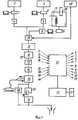
Устройство для перетонеального диализа представлено на чертеже. A device for peritoneal dialysis is shown in the drawing.
Устройство для перетонеального диализа содержит емкости очищенной воды 1 с датчиками уровня (на чертеже не показаны), солевого концентрата 2 и глюкозы 3, оснащенные клапанами 4,5, 6 и 9 с узлами управления, соединенные с емкостями 1,2 и 3 блоки 7 и 8 дозирования вышеуказанных компонентов, блок 10 обеспечения непрерывности диализа, блоки 11 и 12, 13 и 14 подогрева и стерилизации раствора, контроля его температуры и электропроводности, дозаторы 15 и 16 подачи и удаления диализирующего раствора, выполненные в виде эластичных полупрозрачных емкостей 17 с концевыми выключателями 18 и 19, первая из которых расположена выше, а вторая - ниже месте ввода диализирующего раствора. The device for peritoneal dialysis contains containers of purified water 1 with level sensors (not shown in the drawing),
Устройство дополнительно оснащено системой 20 контроля удаляемого диализного раствора, контроллером 21 и задатчиком 22 и контролем отмывки от формалина, причем блок 10 обеспечения непрерывности диализа совмещен с дозатором 15 подачи диализного раствора, блок 11 подогрева установлен в емкости 1 очищенной воды и оснащен дополнительно узлом 28 контроля температуры, выход с емкости 1 очищенной воды, выход блоков дозирования 7 и 8 глюкозы и соли соединены тройником 29, а последний соединен с входом блока 12 стерилизации, блоки 13 и 14 контроля температуры и электропроводности установлены на выходе дозатора 15 подачи диализирующего раствора, система 20 контроля удаляемого диализирующего раствора содержит датчик 30 качества процесса диализа, соединенного с контроллером 21, узел фиксации времени наполнения дозатора удаления диализного раствора 31 также соединен с контроллером 21 и узлом 24 задания времени и объема, а блок 27 контроля отмывки от формалина содержит дополнительную емкость 32 (имитатор живота), подключенный через электромагнитный клапан (на чертеже не показан) между дозаторами 15 и 16 наполнения и слива; каждый из блоков дозирования 7,8 и 9 выполнен в виде регулируемой по объему емкости, узел регулирования которой соединен с контроллером 21, дозаторы 15 и 16 подачи диализируемого раствора размещены на неподвижной пластине 33, в которую вмонтирован один из концевых выключателей 18, датчик 34 закреплен на полупрозрачной емкости 17, а над последней установлена подвижная пластина 35, в которой размещен второй концевой выключатель 19, причем концевые выключатели 18 и 19 соединены с блоками 7,8 и 9 дозирования воды, глюкозы и соли через узел 24 задания объема и времени. The device is additionally equipped with a dialysis solution control system 20, a
Концевой выключатель 18 выполнен в виде геркона, а датчик 34 - в виде магнитной пластины, устройство снабжено пультом 37, связанным через узел 24 задания объема и времени, контроллер 21 с дозатором 15 подачи и блоком 38 ускоренного слива, установленным на выходе из живота (или его имитатора 32). The
На эластичной емкости 18 дозатора 16 удаления диализирующего раствора установлен дополнительный датчик 39, взаимодействующий с дополнительным герконом 40, а последний соединен через систему 41 контроля удаляемого диализирующего раствора и контроллер 21 с дозатором 15 подачи диализирующего раствора. Контроль удаляемого диализирующего раствора может осуществляться, например, путем измерения времени между двумя смежными срабатываниями геркона 40. An
Датчик 43 качества процесса диализа выполнен в виде модуля, контролирующего, например, прозрачность удаляемого диализирующего раствора, установленного на дозаторе 16 удаления диализирующего раствора и соединенного через контроллер 21 с блоком 43 коррекции параметров раствора и с блоком 44 аварийной сигнализации. The
Выход блока 43 коррекции параметров раствора соединен с системой 45 непрерывного приготовления диализирующего раствора, состоящей из емкости 1 очищенной воды с датчиками уровня и контроля температуры 28, емкости 2 солевого концентрата, емкости 3 глюкозы, блоков 7 и 8 дозирования соли и глюкозы, блока 11 подогрева раствора, клапанов 4 и 5 с устройством управления и блока 15 обеспечения непрерывности диализа. The output of the solution
Блок 46 контроля стерилизации раствора устанавливается непосредственно в блоке 12 стерилизации диализирующего раствора и соединяется через контроллер 21 с блоком аварийной сигнализации. Блок контроля стерилизации может быть выполнен, например, в виде фотоэлементов, воспринимающих излучение бактерицидных ламп. При выключении хотя бы одной из ламп на выходе контроллера формируется сигнал аварии. The solution
Блок 13 контроля температуры и блок 14 контроля электропроводности устанавливаются непосредственно перед имитатором живота 32 и представляют собой датчики, соединенные каждый со своим усилителем, аналого-цифровым преобразователем через контроллер 21 с блоком 43 коррекции параметров диализирующего раствора. Блок 43 коррекции параметров раствора выполнен в виде электрической схемы с усилителями мощности на выходе, через которые осуществляется управление блоками 7 и 8 дозирования соли и глюкозы, а также блоком 11 подогрева раствора. The
Блок 47 программ диализа и промывки от формалина представляет собой запоминающее устройство (постоянное или перепрограммируемое), в котором записана и сохраняется программа проведения диализа или промывки гидросистемы от формалина в соответствии с установленным алгоритмом работы устройства.
Блок 43 коррекции параметров диализирующего раствора может быть выполнен на основе электронных схем (см. Граф Р. Электронные схемы, М.: Мир, 1989).
Блок 46 контроля стерилизации раствора может быть выполнен, например, на основе фотодатчиков (см. 750 практических электронных схем под ред.Феликс Р., М.: Мир, 1986, с.464).
Датчик 41 контроля качества процесса диализа может быть выполнен на основе схемы измерения прозрачности раствора с применением фотоусилителей (см. Федорков Б.Г., Телен В.А. Микросхемы ЦАП и АЦП, функционирование, параметры, применение, М.: Энергоатомиздат, 1990, с.64). The
Система контроля удаляемого диализного раствора может быть реализована, например, на основе схем измерения времени между двумя смежными срабатываниями геркона (см. Гутников В.С. Интегральная электроника в измерительных устройствах, Л.: Энергоатомиздат, 1988, с.177). The control system of the removed dialysis solution can be implemented, for example, on the basis of time measurement schemes between two adjacent reed switch trips (see Gutnikov V.S. Integrated Electronics in Measuring Devices, L .: Energoatomizdat, 1988, p. 177).
Задатчик 24 времени и объема может быть реализован, например, аналогично описанному Коломбет Е.А., Таймеры. М.: Радио и связь, 1983, с.49. The
Контроллер 21 может быть выполнен, например, на основе микропроцессорного комплекта (см. Микропроцессоры и микроЭВМ в системах автоматического управления, Л.: Машиностроение, 1987, с.64). The
Блок 44 аварийной сигнализации представляет собой запоминающий регистр с элементами световой и звуковой сигнализации (см. Мальцев Л.А. и др. Основы цифровой техники, М.: Радио и связь, 1986, с.35).
Концевые выключатели 18 и 19 выполнены на герконах, технические характеристики которых приведены в технических условия ОДО.360.038ТУ (геркон КЭМ-2) и ОДО.360.005 (геркон МК-17).
Блок 47 выполнен на микросхемах ОЗУ и ПЗУ, (см. Большие интегральные схемы запоминающих устройство под ред. Гордонова А.Ю. и Дьякова Ю.Н.).
Блок 37 представляет собой панель управления с клавиатурой и элементами индикации (см. Дж.Коффрон Технические средства микропроцессорных систем, М. : Мир, 1983).
Устройство (фиг.2) работает следующим образом. The device (figure 2) works as follows.
Предполагается, что перед включением устройства его гидростатическая система (на фиг. 2 выделена штрихпунктирной линией) всегда заполнена либо формалином в состоянии консервации, либо диализной водой в режиме промывки системы от формалина, либо диализным раствором в режиме диализа. В исходном состоянии емкости блока 15 дозирования - приемного и блока 16 дозирования - сливного опорожнены (см.фиг.1). It is assumed that before turning on the device, its hydrostatic system (shown in FIG. 2 with a dash-dot line) is always filled with either formalin in the preservation state, or dialysis water in the system rinsing system from formalin, or dialysis solution in the dialysis mode. In the initial state, the capacities of the
С целью обеспечения протекания раствора в гидростатической системе самотоком, т.е. без применения насосов, ее блоки размещены в устройстве друг над другом по вертикали в порядке, указанном на фиг.2 (выделено штрихпунктирной линией). In order to ensure the flow of the solution in the hydrostatic system by gravity, i.e. without the use of pumps, its blocks are placed in the device one above the other vertically in the order indicated in figure 2 (highlighted by a dash-dot line).
В момент включения питания формируется сигнал сброса, который устанавливает устройство в исходное состояние. При этом подтверждается выключение блоков 15 и 16 и блока 45 непрерывного приготовления диализного раствора. At the time of power-up, a reset signal is generated, which sets the device to its original state. This confirms the shutdown of
Принцип функционирования аппарата для режима консервации формалином или промывки от формалина или диализа один и тот же. Отличие лишь в задании исходных параметров, таких как общее количество циклов работы; количество доз начального заполнения живота; величины задержки времени; концентрации раствора и т.п. Кроме того, для работы в режиме консервации формалином необходимо произвести отключение 45 от гидросистемы и подключение вместо нее емкости с формалином. The principle of operation of the apparatus for the regimen of formalin preservation or flushing from formalin or dialysis is one and the same. The only difference is in setting the initial parameters, such as the total number of work cycles; the number of doses of the initial filling of the abdomen; time delay values; solution concentration, etc. In addition, to work in the mode of preservation with formalin, it is necessary to disconnect 45 from the hydraulic system and connect instead the tank with formalin.
Работу аппарата рассмотрим на примере его функционирования в режиме ДИАЛИЗ, как наиболее общего. Let us consider the operation of the apparatus by the example of its functioning in the DIALYSIS mode, as the most general.
Работа аппарата в выбранном режиме начинается по команде НАЧАЛО. The operation of the device in the selected mode begins with the START command.
В результате гидростатического давления диализный раствор с заданной концентрацией и вполне определенной температуры начнет перетекать из блока 45 в блок 12 бактерицидной очистки диализного раствора и далее в блок 15 (см. фиг. 1). Дальнейшее его протекание вниз перекрыто клапаном на выходе блока 15. При протекании раствора через блок 12 в нем убиваются все возможные бактерии, например, путем облучения его излучением специальных неоновых ламп. Высокая степень бактерицидной очистки раствора обеспечивается выбором количества источников облучения, их конструкции и скорости протекания раствора. As a result of hydrostatic pressure, a dialysis solution with a given concentration and a well-defined temperature will begin to flow from
В момент заполнения емкости 15 раствором срабатывает выключатель 19, и его сигнал запускает блок 24. Через время, определяемое задатчиком 22, на выходе блока 24 формируется сигнал, который через контроллер 21 выключает 15. На входе 15 клапан закроется, а на выходе откроется, и раствор начнет перетекать в блоки 13 и 14 контроля параметров диализного раствора и далее без задержки в живот пациента или имитатор живота 32. At the moment of filling the
Имитатор живота 32 обычно применяют в режиме консервации системы формалином или в режиме промывки системы от формалина. The simulator of the abdomen 32 is usually used in the mode of preservation of the system with formalin or in the mode of flushing the system from formalin.
В момент опорожнения емкости 15 с выхода 18 уровень сигнала через определенную задержку времени на выходе блока 24 формирует сигнал, по которому контроллер 21 изменяет на единицу состояние счетчика количества доз (СКД), находящегося в контроллере, включается блок 45, и емкость 15 наполняется очищенным диализным раствором установленной концентрации. После заполнения емкости 15 срабатывает выключатель 10, и цикл работы аппарата, описанный выше, повторится. At the moment of emptying the
Такая цикличность будет продолжаться до тех пор, пока не заполнится счетчик количества доз в контроллере 21. Емкость СКД устанавливается медперсоналом посредством задатчика 22, исходя из предполагаемого объема диализного раствора, при котором диализ протекает эффективно, а пациент не ощущает дискомфорта. Such a cycle will continue until the counter of the number of doses in the
При заполнении СКД, например, путем подсчета ста импульсов на выходе контроллера 21 формируется сигнал, который включает блок 16 дозирования сливной одновременно с включением блока 45. При этом одновременно с наполнением емкости блока 15 (фиг.1) будет наполняться в емкость блока 16 отработанным раствором, поступающим из полости живота пациента. When filling the ACS, for example, by counting a hundred pulses at the output of the
В момент заполнения емкости блока 15 срабатывает выключатель 19, запускается блок 24, через время задержки выключаются блоки 45, 15 и 16, в результате чего диализный раствор из емкости 15 перетекает в живот пациента, а отработанный раствор из емкости 16 выливается в канализацию. At the moment of filling the capacity of the
После опорожнения емкости 15 срабатывает выключатель 18, включается блок 24, содержимое СКД увеличивается на единицу, включаются блоки 45, 15 и 16, и емкость 15 наполняется вновь приготовленным диализным раствором, а емкость 16 наполняется отработанным раствором, после заполнения емкости 15 срабатывает выключатель 19 и т.д., по описанной выше схеме. After emptying the
Такая цикличность будет сохраняться до момента заполнения СКД. В этот момент сигналы с выхода контроллера 21 блокируют работу блока 45 и блока 16. Such a cycle will remain until the filling of the access control system. At this moment, the signals from the output of the
Одновременно потенциальный сигнал с выхода контроллера 21 включит блок 38 ускоренного слива отработанного раствора из полости живота пациента в канализацию. В то же время в полость живота пациента будет вливаться последняя доза свежего диализного раствора, а из емкости блока 16 будет выливаться в канализацию отработанный раствор. После опорожнения полости живота пациента СКД может быть сброшен в исходное состояние (на схеме эта цепь не показана) медперсоналом путем подачи сигнала "конец". At the same time, the potential signal from the output of the
В процессе проведения диализа в аппарате предусмотрен контроль параметров диализного раствора (например температуры, концентрации и т.д.) и скорости его вытекания из живота пациента. Для этого в его состав введены: блок 46 контроля бактерицидной очистки (БКБО), блоки 13 и 14 контроля параметров диализного раствора (БКП), блок 41 контроля стабильности раствора (БКСР), блок 42 контроля скорости (БКС) втекания раствора в блок 16. During dialysis, the device provides control of the parameters of the dialysis solution (for example, temperature, concentration, etc.) and its rate of leakage from the patient’s abdomen. For this, it includes: block 46 for controlling bactericidal purification (BKBO), blocks 13 and 14 for controlling parameters of the dialysis solution (BKP), block 41 for controlling the stability of the solution (BKSR), block 42 for controlling the speed (BKS) of the influx of the solution into
Если качество бактерицидной очистки диализного раствора резко снизилось (погасание бактерицидных ламп), то на выходе блока 46 формируется импульс, которым контроллер 21 включает блок 44 аварийной сигнализации. If the quality of bactericidal purification of the dialysis solution has sharply decreased (extinction of bactericidal lamps), then an output is generated at the output of
На выходе блоков 13 и 14 формируется сигнал, характеризующий температуру и электропроводность раствора. Если параметры находятся в безопасных для пациента пределах, то осуществляется коррекция этих параметров для обеспечения оптимального режима диализа. Если хотя бы один из параметров вышел за пределы установленных допусков, через контроллер 21 включается блок 44. At the output of
Для контроля стабильности отработанного раствора введен блок 41. Критерием стабильности раствора, например, может служить его прозрачность. Если наблюдается чрезмерное помутнение раствора, то сигнал с выхода 41 через контроллер включает блок 44.
Блок 42 служит для измерения скорости втекания раствора в емкость блока 16. Изменения в скорости раствора могут быть обусловлены, например, сужением отверстия катетера или разбросом диаметров отверстий в различных катетерах.
В этом случае по сигналу 42 в контроллере устанавливается величина поправки к задержке времени на включение блоков гидростатической системы. Если этого не предусмотреть, то в результате различия скорости втекания в живот и вытекания раствора из живота пациента объем раствора находящийся в полости живота будет накопительно увеличиваться или уменьшаться. In this case, the
Claims (4)
Translated fromRussianPriority Applications (1)
| Application Number | Priority Date | Filing Date | Title |
|---|---|---|---|
| SU4913472RU2031662C1 (en) | 1991-01-03 | 1991-01-03 | Apparatus for peritoneal dialysis |
Applications Claiming Priority (1)
| Application Number | Priority Date | Filing Date | Title |
|---|---|---|---|
| SU4913472RU2031662C1 (en) | 1991-01-03 | 1991-01-03 | Apparatus for peritoneal dialysis |
Publications (1)
| Publication Number | Publication Date |
|---|---|
| RU2031662C1true RU2031662C1 (en) | 1995-03-27 |
Family
ID=21561760
Family Applications (1)
| Application Number | Title | Priority Date | Filing Date |
|---|---|---|---|
| SU4913472RU2031662C1 (en) | 1991-01-03 | 1991-01-03 | Apparatus for peritoneal dialysis |
Country Status (1)
| Country | Link |
|---|---|
| RU (1) | RU2031662C1 (en) |
Cited By (2)
| Publication number | Priority date | Publication date | Assignee | Title |
|---|---|---|---|---|
| RU2396218C2 (en)* | 2006-04-21 | 2010-08-10 | Нихон Трим Ко., Лтд. | Water for obtaining dialysing solution, dialysing solution with said water application, methods of obtaining dialysing solution and device for dialysis |
| RU2426561C2 (en)* | 2006-01-30 | 2011-08-20 | Дзе Риджентс Оф Дзе Юниверсити Оф Калифорния | Methods and device for peritoneal dialysis |
- 1991
- 1991-01-03RUSU4913472patent/RU2031662C1/enactive
Non-Patent Citations (1)
| Title |
|---|
| Авторское свидетельство СССР N 1593660, кл. A 61M 1/28, 1987.* |
Cited By (2)
| Publication number | Priority date | Publication date | Assignee | Title |
|---|---|---|---|---|
| RU2426561C2 (en)* | 2006-01-30 | 2011-08-20 | Дзе Риджентс Оф Дзе Юниверсити Оф Калифорния | Methods and device for peritoneal dialysis |
| RU2396218C2 (en)* | 2006-04-21 | 2010-08-10 | Нихон Трим Ко., Лтд. | Water for obtaining dialysing solution, dialysing solution with said water application, methods of obtaining dialysing solution and device for dialysis |
Similar Documents
| Publication | Publication Date | Title |
|---|---|---|
| JP2607798Y2 (en) | System for performing continuous peritoneal dialysis | |
| JP6675015B2 (en) | System and method for peritoneal dialysis with dialysis fluid preparation at the point of use and including mixing and heating | |
| ES2202309T3 (en) | METHOD AND APPLIANCE FOR RENAL DIALYSIS. | |
| US5004459A (en) | Continuous cyclic peritoneal dialysis system and method | |
| JP3714947B2 (en) | Blood purification equipment | |
| US3545438A (en) | Intermittent dialysis method and apparatus therefor | |
| CA2211848C (en) | Peritoneal dialysis apparatus | |
| CA2686319C (en) | A device for connecting to a liquid source | |
| CA1065224A (en) | Peritoneal dialysis apparatus | |
| EP0402505A1 (en) | Continuous cyclic peritoneal dialysis system | |
| JPH10201842A (en) | Method for adjusting electric conductivity of dialyzate batch of dialysis apparatus and apparatus therefor | |
| JPH0152026B2 (en) | ||
| JPH1080476A (en) | Method for disinfecting dialysis machine | |
| GB2135598A (en) | Apparatus for preparation of a medical infusion solution | |
| JP2003199819A (en) | Modular type home dialyzing system | |
| JPH10510747A (en) | Waste sample collection equipment | |
| US10369261B2 (en) | Method and device for supplying dialysis liquid to a dialysis apparatus | |
| CN201871012U (en) | Solution supply and dispensing system of hemodialysis machine | |
| RU2031662C1 (en) | Apparatus for peritoneal dialysis | |
| EP0565585B1 (en) | Hemodialysis apparatus | |
| US3457944A (en) | Hemodialysis system | |
| JP4337981B2 (en) | Blood purification equipment | |
| JPH0533063B2 (en) | ||
| JPH07270214A (en) | Method and device for detecting salt water level and salt water concentration in salt water tank of water softener | |
| US20030031590A1 (en) | Apparatus for measuring amount of hemodialysis |