RU2025890C1 - Method of control over synchronous motor under oscillation condition - Google Patents
Method of control over synchronous motor under oscillation conditionDownload PDFInfo
- Publication number
- RU2025890C1 RU2025890C1SU5012785ARU2025890C1RU 2025890 C1RU2025890 C1RU 2025890C1SU 5012785 ASU5012785 ASU 5012785ARU 2025890 C1RU2025890 C1RU 2025890C1
- Authority
- RU
- Russia
- Prior art keywords
- winding
- synchronous motor
- current
- mode
- resonance
- Prior art date
Links
- 230000010355oscillationEffects0.000titleclaimsabstractdescription28
- 230000001360synchronised effectEffects0.000titleclaimsabstractdescription27
- 238000000034methodMethods0.000titleclaimsabstractdescription25
- 238000004804windingMethods0.000claimsabstractdescription51
- 238000004870electrical engineeringMethods0.000abstractdescription3
- 230000008569processEffects0.000abstractdescription2
- 230000000694effectsEffects0.000abstract1
- 238000005259measurementMethods0.000abstract1
- 239000000126substanceSubstances0.000abstract1
- 230000001276controlling effectEffects0.000description9
- 230000003534oscillatory effectEffects0.000description7
- 238000010586diagramMethods0.000description4
- 230000033001locomotionEffects0.000description4
- 230000007935neutral effectEffects0.000description4
- 230000004907fluxEffects0.000description3
- 230000001105regulatory effectEffects0.000description3
- 230000009471actionEffects0.000description2
- 230000033228biological regulationEffects0.000description2
- 230000008859changeEffects0.000description2
- 230000005672electromagnetic fieldEffects0.000description2
- 230000003993interactionEffects0.000description2
- 238000004886process controlMethods0.000description2
- 238000013016dampingMethods0.000description1
- 230000001419dependent effectEffects0.000description1
- 238000001514detection methodMethods0.000description1
- 239000000314lubricantSubstances0.000description1
- 238000012423maintenanceMethods0.000description1
- 238000013178mathematical modelMethods0.000description1
- 238000011089mechanical engineeringMethods0.000description1
- 230000010363phase shiftEffects0.000description1
- 230000008092positive effectEffects0.000description1
Images


Landscapes
- Reciprocating, Oscillating Or Vibrating Motors (AREA)
Abstract
Description
Translated fromRussianИзобретение относится к электротехнике и предназначено для использования в исполнительных устройствах систем управления технологическими процессами. The invention relates to electrical engineering and is intended for use in actuators of process control systems.
Известен способ управления синхронным двигателем в режиме колебаний, включающий питание одной обмотки статора и одной обмотки ротора переменным током с частотой, равной частоте питания двигателя, а другой обмотки статора и другой обмотки ротора переменным током другой частоты [1]. A known method of controlling a synchronous motor in an oscillation mode, including powering one stator winding and one rotor winding with alternating current with a frequency equal to the frequency of the motor, and another stator winding and another rotor winding with alternating current of a different frequency [1].
При управлении синхронным двигателем по известному способу синусоидальные управляющие напряжения в воздушном зазоре создают два синфазно направленных колебательных электромагнитных поля. В результате согласного взаимодействия электромагнитных полей статора и ротора подвижный элемент двигателя совершает синхронные с частотой колебания магнитного поля статора колебательного движения. When controlling a synchronous motor according to a known method, sinusoidal control voltages in the air gap create two in-phase directed vibrational electromagnetic fields. As a result of the consonant interaction of the electromagnetic fields of the stator and rotor, the movable element of the motor performs oscillations synchronous with the frequency of oscillation of the magnetic field of the stator.
Известно, что КПД колебательного электропривода достигает максимального значения при резонансном режиме его работы. Однако в известном способе поддержание резонансного режима работы привода при изменениях параметров нагрузки не предусматривается. Следовательно, недостаток известного способа - низкий КПД при изменениях нагрузки. It is known that the efficiency of an oscillating electric drive reaches its maximum value in the resonant mode of its operation. However, in the known method, maintaining the resonant mode of operation of the drive when changing the load parameters is not provided. Therefore, the disadvantage of this method is the low efficiency with changes in load.
Известен также способ управления синхронным двигателем в режиме колебаний, включающий питание обмотки статора переменным током [2]. В соответствии с этим способом якорь двигателя, состоящий из постоянного магнита с полюсным наконечником и установленный в начальное нейтральное положение с помощью механических пружин, совершает колебания под действием магнитного поля, создаваемого переменным током в обмотке статора. There is also known a method of controlling a synchronous motor in an oscillation mode, comprising supplying the stator winding with alternating current [2]. In accordance with this method, the motor armature, consisting of a permanent magnet with a pole tip and set to its initial neutral position by means of mechanical springs, vibrates under the influence of a magnetic field created by alternating current in the stator winding.
Такой способ управления синхронным двигателем не обеспечивает высокого КПД, поскольку режим работы находится в зависимости от параметров механической нагрузки. Жесткость механических пружин постоянна и не позволяет регулировать режим работы двигателя с целью поддержания резонанса. Следовательно, недостаток известного способа управления синхронным двигателем в режиме колебаний - низкий КПД. This method of controlling a synchronous motor does not provide high efficiency, since the mode of operation is dependent on the parameters of the mechanical load. The stiffness of the mechanical springs is constant and does not allow you to adjust the operating mode of the engine in order to maintain resonance. Therefore, the disadvantage of the known method of controlling a synchronous motor in the oscillation mode is low efficiency.
Наиболее близким по достигаемому результату к предлагаемому является способ управления синхронным двигателем в режиме колебаний, включающий питание одной из обмоток статора постоянным током, а другой - переменным [3]. При таком способе ротор синхронного двигателя с постоянными магнитами совершает колебательное движение под действием сигналов переменного тока, подаваемых в одну или две обмотки статора. Так как параметры колебательного движения зависят от параметров механической нагрузки двигателя, то КПД двигателя является переменным. Наилучшим с энергетической точки зрения режимом работы колебательного привода является резонансный. The closest to the achieved result to the proposed one is a method of controlling a synchronous motor in an oscillation mode, including supplying one of the stator windings with direct current, and the other with alternating [3]. With this method, the rotor of a permanent magnet synchronous motor makes an oscillatory motion under the action of alternating current signals supplied to one or two stator windings. Since the parameters of the oscillatory motion depend on the parameters of the mechanical load of the engine, the efficiency of the engine is variable. The best mode of operation of an oscillatory drive from an energy point of view is resonant.
Однако в известном способе поддержание этого режима не предусматривается. Поэтому при изменениях нагрузки двигателя известный способ не обеспечивает высокого КПД. Таким образом, недостаток известного способа управления синхронным двигателем в режиме колебаний - низкий КПД при изменениях параметров механической нагрузки. However, in the known method, the maintenance of this mode is not provided. Therefore, when the engine load changes, the known method does not provide high efficiency. Thus, the disadvantage of the known method of controlling a synchronous motor in the oscillation mode is the low efficiency when changing the parameters of the mechanical load.
Цель изобретения - повышение КПД путем обеспечения резонансного режима работы синхронного двигателя при изменениях параметров нагрузки. The purpose of the invention is to increase efficiency by providing a resonant mode of operation of a synchronous motor with changes in load parameters.
Цель достигается тем, что по способу управления синхронным двигателем в режиме колебаний, включающему питание одной из обмоток статора постоянным током, а другой - переменным, дополнительно измеряют переменные напряжения и ток второй обмотки и устанавливают величину постоянного тока в первой обмотке такой, при которой электрические колебания во второй обмотке находятся в резонансном режиме. The goal is achieved by the fact that according to the method of controlling a synchronous motor in an oscillation mode, which includes supplying one of the stator windings with direct current, and the other with alternating current, alternating voltages and currents of the second winding are additionally measured and the direct current in the first winding is set such that electric oscillations in the second winding are in resonance mode.
По сравнению с наиболее близким аналогичным техническим решением предлагаемый способ имеет следующие отличительные признаки: измеряют напряжение и ток второй обмотки, устанавливают величину постоянного тока в первой обмотке такой, при которой электрические колебания во второй обмотке находятся в резонансном режиме. Следовательно, предлагаемое техническое решение соответствует требованию "новизна". Compared with the closest similar technical solution, the proposed method has the following distinctive features: the voltage and current of the second winding are measured, the direct current in the first winding is set such that the electric oscillations in the second winding are in resonant mode. Therefore, the proposed technical solution meets the requirement of "novelty."
При реализации изобретения повышается КПД синхронного двигателя путем обеспечения резонансного режима работы. Следовательно, заявляемое техническое решение соответствует требованию "положительный эффект". When implementing the invention increases the efficiency of the synchronous motor by providing a resonant mode of operation. Therefore, the claimed technical solution meets the requirement of "positive effect".
По каждому отличительному признаку проведен поиск известных технических решений в области электротехники и электропривода. Операции измерения напряжения и тока второй обмотки и установления величины постоянного тока такой, при которой электрические колебания во второй обмотке находятся в резонансном режиме в известных способах аналогичного назначения, не обнаружены. Следовательно, известное техническое решение соответствует требованию "существенные отличия". For each distinguishing feature, a search is made for known technical solutions in the field of electrical engineering and electric drive. The operation of measuring the voltage and current of the second winding and setting the magnitude of the direct current such that electric oscillations in the second winding are in resonance mode in known methods for a similar purpose are not detected. Therefore, the known technical solution meets the requirement of "significant differences".
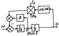
На фиг.1 приведена функциональная схема реализации способа; на фиг.2 - структурная схема механической части синхронного двигателя в режиме колебаний; на фиг.3 приведены экспериментальные зависимости амплитуды колебаний ротора от частоты переменного тока во второй обмотке при различных значениях величины постоянного тока в первой обмотке статора. Figure 1 shows the functional diagram of the implementation of the method; figure 2 is a structural diagram of the mechanical part of a synchronous motor in vibration mode; figure 3 shows the experimental dependence of the amplitude of the oscillations of the rotor on the frequency of the alternating current in the second winding at various values of the direct current in the first stator winding.
На схеме (фиг.1) 1 - регулируемый источник постоянного тока, 2 - источник переменного тока, 3 и 6 - первая и вторая обмотки статора синхронного двигателя, 4 - датчик тока, 5 - ротор синхронного двигателя, 7 - датчик напряжения, 8 - блок определения резонанса. Первая обмотка 3 статора синхронного двигателя подключена к регулируемому источнику 1 постоянного тока, вторая обмотка 6 - к источнику 2 переменного тока. Последовательно с второй обмоткой 6 включен датчик тока 4, параллельно с второй обмоткой 6 соединен датчик 7 напряжения. Выходы датчика 4 тока и датчика 7 напряжения подключены к входам блока 8 определения резонанса, выход которого подключен к управляющему входу источника 1 постоянного тока. In the diagram (Fig. 1) 1 is an adjustable direct current source, 2 is an alternating current source, 3 and 6 are the first and second stator windings of a synchronous motor, 4 is a current sensor, 5 is a synchronous motor rotor, 7 is a voltage sensor, 8 is resonance detection unit. The first winding 3 of the stator of the synchronous motor is connected to an adjustable source of
Постоянные магниты, расположенные на роторе 5 двигателя, создают намагничивающий поток Φо. При подключении первой обмотки 3 статора двигателя к источнику 1 постоянного тока по ней протекает ток Iо. В результате взаимодействия обмотки 3 с током Iо и магнитного поля Φоротор 5 синхронного двигателя поворачивается и занимает нейтральное положение, соответствующее минимуму энергии электромеханической системы. При повороте ротора 5 относительно этого нейтрального положения на угол α на него действует момент
Mв = k Io Φo sin α , (1) где k - коэффициент пропорциональности, стремящийся вернуть ротор в исходное положение. Следовательно, первая обмотка 3, подключенная к источнику 1 постоянного тока, выполняет функцию электрической пружины, жесткость которой, как следует из уравнения (1), пропорциональная постоянному току Iо.Permanent magnets located on the
Min = k Io Φo sin α, (1) where k is the proportionality coefficient, tending to return the rotor to its original position. Therefore, the first winding 3 connected to the direct
Переменный ток во второй обмотке 6 статора синхронного двигателя создает переменный магнитный поток, под действием которого ротор 5 совершает колебательное движение относительно нейтрального положения. Частота колебаний при этом определяется частотой переменного тока во второй обмотке 6. Амплитуда колебаний зависит от параметров двигателя, величины питающего переменного тока, жесткости электрической пружины и момента инерции механической нагрузки. Наилучший режим работы такой системы резонансный. В этом режиме активный ток в обмотке 6 минимален, а амплитуда колебаний ротора максимальна. С целью контроля резонансного режима с помощью датчика 4 тока измеряется переменный ток, а с помощью датчика 7 напряжения - переменное напряжение, приложенное к второй обмотке 6. Сигналы с выходов датчиков тока 4 и напряжения 7 поступают на входы блока 8 определения резонанса, на выходе которого формируется напряжение, пропорциональное отклонению параметра, характеризующего режим колебаний, от значения, соответствующего резонансу. В качестве таких параметров могут использоваться различные физические величины, например фазовый сдвиг между током и напряжением, минимум активного тока и др. (см., например, Кораблев С.С., Шапин В.И., Филатов Ю.Е. Вибродиагностика в прецизионном приборостроении. - Л.: Машиностроение, 1984, с. 64-81). Сигнал с выхода блока 8 определения резонанса поступает на управляющий вход регулируемого источника 1 постоянного тока, в результате чего происходит уменьшение или увеличение постоянного тока Iов первой обмотке 3 синхронного двигателя. За счет действия обратной связи в обмотке устанавливается постоянный ток такой величины, при которой в обмотке 6 переменного тока имеет место резонанс. При изменении момента инерции нагрузки изменяется резонансная частота системы. Это приводит к изменению выходного сигнала блока 8 определения резонанса и, следовательно, изменению тока Iо в первой обмотке 3, благодаря чему восстанавливается резонансный режим колебаний. Таким образом, при любых изменениях параметров механической нагрузки поддерживается резонансный режим колебаний ротора синхронного двигателя и, следовательно, поддерживается максимальный КПД.The alternating current in the second winding 6 of the stator of the synchronous motor creates an alternating magnetic flux, under the action of which the
С целью аналитического подтверждения способа регулирования резонансного режима колебаний синхронного двигателя рассмотрим математическую модель механической части колебательной системы. Такая модель в виде структурной схемы показана на фиг.2, где М - электромагнитный момент, развиваемый двигателем; J - момент инерции колеблющейся части; β- коэффициент пропорциональности между моментом сопротивления среды и скоростью Ω колебаний, отражающий вязкое трение в механической системе, например, смазки; Ω - скорость колебаний; α - угол поворота ротора; Φо - магнитный поток, создаваемый постоянными магнитами ротора; Iо - ток в обмотке 3 статора; k - коэффициент пропорциональности, характеризующий зависимость синхронизирующего момента Mc = k Io Φo sinα от угла поворота α ; S - оператор Лапласа.In order to analytically confirm the method for regulating the resonant mode of oscillations of a synchronous motor, we consider a mathematical model of the mechanical part of the oscillatory system. Such a model in the form of a structural diagram is shown in figure 2, where M is the electromagnetic moment developed by the engine; J is the moment of inertia of the oscillating part; β is the coefficient of proportionality between the moment of resistance of the medium and the speed Ω of oscillations, which reflects viscous friction in a mechanical system, for example, a lubricant; Ω is the oscillation velocity; α is the angle of rotation of the rotor; Φabout - magnetic flux generated by the permanent magnets of the rotor; Iabout - current in the winding 3 of the stator; k is the proportionality coefficient characterizing the dependence of the synchronizing moment Mc = k Io Φo sinα on the rotation angle α; S is the Laplace operator.
При малых значениях α можно принять sin α ≈ α . В этом случае передаточная функция механической части системы по углу поворота α относительно электромагнитного момента имеет вид


(2) где Ko =
Tэ =
ζ =

(2) where Ko =
Te =
ζ =
Из выражения (2) следует, что механическая часть синхронного двигателя представляет собой в динамическом отношении колебательное звено с постоянной времени Тэ и параметром затухания ζ . Резонансная частота этого звена (см. например, Бесекерский В.А., Попов Е.П. Теория систем автоматического регулирования и управления. - М.: Наука, 1972, с.74-79) равна ωp =

Из уравнения (3) следует, что двигатель работает в колебательном режиме с максимальным КПД в том случае, если частота питающего напряжения, приложенного к обмотке 6, совпадает с резонансной частотой ωр . В процессе работы происходят изменения момента инерции J колеблющейся части, а также коэффициента β , характеризующего трение. В результате изменяется резонансная частота ωр, что может привести к снижению КПД. Однако регулирование тока Iо в обмотке 3 дает возможность скомпенсировать эти изменения резонансной частоты и обеспечить ее постоянство, т.е. равенство частоте питающего напряжения. Уравнение для тока Iо, при котором обеспечивается постоянство заданной резонансной частоты ωр, легко вывести из выражения (3) и имеет вид
Io=


From equation (3) it follows that the engine operates in an oscillatory mode with maximum efficiency if the frequency of the supply voltage applied to the winding 6 coincides with the resonant frequency ωp . In the process, changes occur in the moment of inertia J of the oscillating part, as well as the coefficient β characterizing friction. As a result, the resonance frequency ωr changes, which can lead to a decrease in efficiency. However, the regulation of the current Io in the winding 3 makes it possible to compensate for these changes in the resonant frequency and ensure its constancy, i.e. equality of the frequency of the supply voltage. The equation for the current Io , at which the given resonance frequency ωp is constant, is easily derived from expression (3) and has the form
Io =
На фиг.3 приведены экспериментальные зависимости амплитуды αмколебаний ротора от частоты, полученные при различных значениях постоянного тока Iо в обмотке синхронного двигателя типа 2ДВУ. Приведенные кривые подтверждают возможности регулирования резонансной частоты механической системы путем изменения постоянного тока в обмотке статора.Figure 3 shows the experimental dependence of the amplitude αm of the rotor oscillations on frequency, obtained at various values of direct current Iabout in the winding of a synchronous motor of type 2DVU. These curves confirm the possibility of regulating the resonant frequency of the mechanical system by changing the direct current in the stator winding.
Таким образом, использование в известном способе управления синхронным двигателем в режиме колебаний, включающем питание одной из обмоток статора постоянным током, а другой - переменным, дополнительно измерения переменных напряжения и тока второй обмотки и установления величины постоянного тока в первой обмотке такой, при которой электрические колебания во второй обмотке находятся в резонансном режиме, позволяет повысить КПД двигателя. Thus, the use in a known method of controlling a synchronous motor in an oscillation mode, including supplying one of the stator windings with direct current, and the other with alternating current, additionally measuring the alternating voltage and current of the second winding and setting the magnitude of the direct current in the first winding such that electric vibrations in the second winding they are in resonance mode, which makes it possible to increase the motor efficiency.
Использование изобретения в исполнительных устройствах автоматических систем управления технологическими процессами с колебательным движением регулирующего органа позволит повысить эффективность их работы и уменьшить потери электроэнергии. The use of the invention in actuators of automatic process control systems with oscillatory movement of the regulatory body will improve their efficiency and reduce energy losses.
Claims (1)
Translated fromRussianPriority Applications (1)
| Application Number | Priority Date | Filing Date | Title |
|---|---|---|---|
| SU5012785RU2025890C1 (en) | 1991-11-28 | 1991-11-28 | Method of control over synchronous motor under oscillation condition |
Applications Claiming Priority (1)
| Application Number | Priority Date | Filing Date | Title |
|---|---|---|---|
| SU5012785RU2025890C1 (en) | 1991-11-28 | 1991-11-28 | Method of control over synchronous motor under oscillation condition |
Publications (1)
| Publication Number | Publication Date |
|---|---|
| RU2025890C1true RU2025890C1 (en) | 1994-12-30 |
Family
ID=21589635
Family Applications (1)
| Application Number | Title | Priority Date | Filing Date |
|---|---|---|---|
| SU5012785RU2025890C1 (en) | 1991-11-28 | 1991-11-28 | Method of control over synchronous motor under oscillation condition |
Country Status (1)
| Country | Link |
|---|---|
| RU (1) | RU2025890C1 (en) |
Cited By (1)
| Publication number | Priority date | Publication date | Assignee | Title |
|---|---|---|---|---|
| RU2725897C1 (en)* | 2019-08-02 | 2020-07-07 | Федеральное государственное бюджетное образовательное учреждение высшего образования "Владимирский Государственный Университет имени Александра Григорьевича и Николая Григорьевича Столетовых" (ВлГУ) | Excitation method of mechanical self-oscillations |
- 1991
- 1991-11-28RUSU5012785patent/RU2025890C1/enactive
Non-Patent Citations (3)
| Title |
|---|
| 1. Авторское свидетельство СССР N 1307530, кл. H 02P 7/62, 1987.* |
| 2. Патент ФРГ N 2323494, кл. H 02K 33/06, 1974.* |
| 3. Авторское свидетельство СССР N 1448380, кл. H 02P 7/62, 1988.* |
Cited By (1)
| Publication number | Priority date | Publication date | Assignee | Title |
|---|---|---|---|---|
| RU2725897C1 (en)* | 2019-08-02 | 2020-07-07 | Федеральное государственное бюджетное образовательное учреждение высшего образования "Владимирский Государственный Университет имени Александра Григорьевича и Николая Григорьевича Столетовых" (ВлГУ) | Excitation method of mechanical self-oscillations |
Similar Documents
| Publication | Publication Date | Title |
|---|---|---|
| US5359154A (en) | Conveyor apparatus having plural conveyors with equalized conveying speeds controlled by an inverter means | |
| US7474065B2 (en) | Controlling an electric motor having multiple oscillatory elements | |
| JP4229909B2 (en) | Vibration electric motor control method for small electrical equipment | |
| US4275343A (en) | Back EMF controlled permanent magnet motor | |
| SU1609515A1 (en) | Method and apparatus for exciting resonant vibrations of mechanical system | |
| JPS63501321A (en) | Scanner for industrial laser equipment | |
| RU2025890C1 (en) | Method of control over synchronous motor under oscillation condition | |
| US3040223A (en) | Oscillatory drive circuit | |
| JP2003348888A (en) | Drive control unit for linear actuator and linear actuator using the same | |
| RU2076439C1 (en) | Method for excitation of oscillations in synchronous motor | |
| RU2050687C1 (en) | Electric motor drive of oscillatory motion | |
| KR100376007B1 (en) | Self-excited vibration type vibration device with electromagnet | |
| RU2706340C1 (en) | Control method of synchronous motor in oscillation mode | |
| RU2725897C1 (en) | Excitation method of mechanical self-oscillations | |
| RU2793608C1 (en) | Generator of mechanical auto-oscillations | |
| US3264881A (en) | Power supply for gyroscopes | |
| RU2077036C1 (en) | Resonance method of measurement of moment of inertia of articles of type of bodies of revolution | |
| US2965824A (en) | Cyclic motor | |
| US3448363A (en) | Speed control system for a dynamoelectric machine | |
| SU982070A1 (en) | Device for demonstrating oscillations | |
| RU2148293C1 (en) | Oscillating movement electric drive | |
| SU1005259A1 (en) | Device for stabilizing frequency of ac generator driven by internal combustion engine | |
| RU2359398C1 (en) | Viscous ferromagnetic motor | |
| RU2410701C1 (en) | Micromechanical sensor of angular speed | |
| SU1500389A1 (en) | Electromagnetic vibration exciter |