RU2023438C1 - Blood vessel prosthesis - Google Patents
Blood vessel prosthesisDownload PDFInfo
- Publication number
- RU2023438C1 RU2023438C1SU843781696ASU3781696ARU2023438C1RU 2023438 C1RU2023438 C1RU 2023438C1SU 843781696 ASU843781696 ASU 843781696ASU 3781696 ASU3781696 ASU 3781696ARU 2023438 C1RU2023438 C1RU 2023438C1
- Authority
- RU
- Russia
- Prior art keywords
- blood
- passage
- prosthesis according
- channel
- section
- Prior art date
Links
- 210000004204blood vesselAnatomy0.000titleabstractdescription11
- 239000008280bloodSubstances0.000claimsabstractdescription31
- 210000004369bloodAnatomy0.000claimsabstractdescription31
- 230000017531blood circulationEffects0.000claimsabstractdescription29
- 230000002792vascularEffects0.000claimsdescription8
- 210000004351coronary vesselAnatomy0.000claimsdescription6
- 239000000835fiberSubstances0.000claimsdescription5
- 239000000560biocompatible materialSubstances0.000claimsdescription3
- 230000003014reinforcing effectEffects0.000claimsdescription2
- 230000036772blood pressureEffects0.000abstractdescription5
- 230000036770blood supplyEffects0.000abstractdescription4
- 201000001320AtherosclerosisDiseases0.000abstract1
- 208000032170Congenital AbnormalitiesDiseases0.000abstract1
- 208000037919acquired diseaseDiseases0.000abstract1
- 230000006378damageEffects0.000abstract1
- 208000037265diseases, disorders, signs and symptomsDiseases0.000abstract1
- 230000000694effectsEffects0.000abstract1
- 210000000056organAnatomy0.000abstract1
- 230000001105regulatory effectEffects0.000abstract1
- 239000000126substanceSubstances0.000abstract1
- 238000001356surgical procedureMethods0.000abstract1
- 210000001367arteryAnatomy0.000description7
- 210000002837heart atriumAnatomy0.000description5
- 210000003954umbilical cordAnatomy0.000description5
- 230000003872anastomosisEffects0.000description4
- 210000000709aortaAnatomy0.000description3
- 239000000463materialSubstances0.000description3
- 210000005003heart tissueAnatomy0.000description2
- 239000007943implantSubstances0.000description2
- 210000005246left atriumAnatomy0.000description2
- 210000001519tissueAnatomy0.000description2
- 241000283690Bos taurusSpecies0.000description1
- 229920000049Carbon (fiber)Polymers0.000description1
- 241000282324FelisSpecies0.000description1
- 241001465754MetazoaSpecies0.000description1
- 241001494479PecoraSpecies0.000description1
- 230000003881arterial anastomosisEffects0.000description1
- 239000004917carbon fiberSubstances0.000description1
- 210000001715carotid arteryAnatomy0.000description1
- 239000003795chemical substances by applicationSubstances0.000description1
- 230000015271coagulationEffects0.000description1
- 238000005345coagulationMethods0.000description1
- 210000003238esophagusAnatomy0.000description1
- 210000001105femoral arteryAnatomy0.000description1
- 210000000936intestineAnatomy0.000description1
- 210000005240left ventricleAnatomy0.000description1
- 210000003141lower extremityAnatomy0.000description1
- 238000012423maintenanceMethods0.000description1
- 239000002184metalSubstances0.000description1
- 238000000034methodMethods0.000description1
- QJGQUHMNIGDVPM-UHFFFAOYSA-Nnitrogen groupChemical group[N]QJGQUHMNIGDVPM-UHFFFAOYSA-N0.000description1
- 230000010412perfusionEffects0.000description1
- 230000002093peripheral effectEffects0.000description1
- 239000004033plasticSubstances0.000description1
- 229920000728polyesterPolymers0.000description1
- -1polytetrafluoroethylenePolymers0.000description1
- 229920001343polytetrafluoroethylenePolymers0.000description1
- 239000004810polytetrafluoroethyleneSubstances0.000description1
- 210000003137popliteal arteryAnatomy0.000description1
- 210000003513popliteal veinAnatomy0.000description1
- 230000000250revascularizationEffects0.000description1
- 210000005245right atriumAnatomy0.000description1
- 210000003752saphenous veinAnatomy0.000description1
Images


Classifications
- A—HUMAN NECESSITIES
- A61—MEDICAL OR VETERINARY SCIENCE; HYGIENE
- A61F—FILTERS IMPLANTABLE INTO BLOOD VESSELS; PROSTHESES; DEVICES PROVIDING PATENCY TO, OR PREVENTING COLLAPSING OF, TUBULAR STRUCTURES OF THE BODY, e.g. STENTS; ORTHOPAEDIC, NURSING OR CONTRACEPTIVE DEVICES; FOMENTATION; TREATMENT OR PROTECTION OF EYES OR EARS; BANDAGES, DRESSINGS OR ABSORBENT PADS; FIRST-AID KITS
- A61F2/00—Filters implantable into blood vessels; Prostheses, i.e. artificial substitutes or replacements for parts of the body; Appliances for connecting them with the body; Devices providing patency to, or preventing collapsing of, tubular structures of the body, e.g. stents
- A61F2/02—Prostheses implantable into the body
- A61F2/04—Hollow or tubular parts of organs, e.g. bladders, tracheae, bronchi or bile ducts
- A61F2/06—Blood vessels
- Y—GENERAL TAGGING OF NEW TECHNOLOGICAL DEVELOPMENTS; GENERAL TAGGING OF CROSS-SECTIONAL TECHNOLOGIES SPANNING OVER SEVERAL SECTIONS OF THE IPC; TECHNICAL SUBJECTS COVERED BY FORMER USPC CROSS-REFERENCE ART COLLECTIONS [XRACs] AND DIGESTS
- Y10—TECHNICAL SUBJECTS COVERED BY FORMER USPC
- Y10S—TECHNICAL SUBJECTS COVERED BY FORMER USPC CROSS-REFERENCE ART COLLECTIONS [XRACs] AND DIGESTS
- Y10S623/00—Prosthesis, i.e. artificial body members, parts thereof, or aids and accessories therefor
- Y10S623/902—Method of implanting
- Y10S623/903—Blood vessel
Landscapes
- Health & Medical Sciences (AREA)
- Veterinary Medicine (AREA)
- Life Sciences & Earth Sciences (AREA)
- Cardiology (AREA)
- Oral & Maxillofacial Surgery (AREA)
- Transplantation (AREA)
- Engineering & Computer Science (AREA)
- Biomedical Technology (AREA)
- Heart & Thoracic Surgery (AREA)
- Vascular Medicine (AREA)
- Gastroenterology & Hepatology (AREA)
- Animal Behavior & Ethology (AREA)
- General Health & Medical Sciences (AREA)
- Pulmonology (AREA)
- Public Health (AREA)
- Prostheses (AREA)
- Graft Or Block Polymers (AREA)
- Materials For Medical Uses (AREA)
- External Artificial Organs (AREA)
- Laser Surgery Devices (AREA)
- Electrotherapy Devices (AREA)
- Pharmaceuticals Containing Other Organic And Inorganic Compounds (AREA)
- Addition Polymer Or Copolymer, Post-Treatments, Or Chemical Modifications (AREA)
- Detergent Compositions (AREA)
- Medicines That Contain Protein Lipid Enzymes And Other Medicines (AREA)
- Ultra Sonic Daignosis Equipment (AREA)
- Heterocyclic Carbon Compounds Containing A Hetero Ring Having Oxygen Or Sulfur (AREA)
- Peptides Or Proteins (AREA)
Abstract
Description
Translated fromRussianИзобретение относится к медицинской технике, точнее к трансплантатам, применяемым для замены в организме естественных кровеносных сосудов для подачи артериальной крови. В частности, имплантаты представляют собой сосудистые трансплантаты. The invention relates to medical equipment, more specifically to transplants used to replace in the body natural blood vessels for supplying arterial blood. In particular, implants are vascular grafts.
Известны синтетические сосудистые трансплантаты. Эти трансплантаты представляют собой удлиненные трикотажные трубки, изготовленные, например, из полиэфирного волокна. Известно использование пуповины для сосудистого трансплантата, способ подготовки пуповины человека и животных для использования в качестве сосудистого трансплантата. Тканевые трубки и пуповина применяются для замены имплантата подкожной вены. Концы трубок и пуповин анастомозируются с концами артерий для обхода пораженных областей артерий. Они заменяют пораженные части артерий. Известен протез кровеносного сосуда, содержащий корпус из биосовместимого материала с каналом, имеющим входное и выходное отверстия, причем в корпусе выполнены отверстия, соединенные с каналом для прохождения крови [1]. Synthetic vascular grafts are known. These grafts are elongated knit tubes made, for example, of polyester fiber. It is known to use an umbilical cord for a vascular graft, a method for preparing a human and animal cord for use as a vascular graft. Tissue tubes and umbilical cord are used to replace the saphenous vein implant. The ends of the tubes and umbilical cord anastomose with the ends of the arteries to bypass the affected areas of the arteries. They replace the affected parts of the arteries. Known prosthesis of a blood vessel containing a body of biocompatible material with a channel having an inlet and an outlet, and in the case there are holes connected to the channel for the passage of blood [1].
Цель изобретения - поддержание непрерывного потока крови с заданным давлением, непрерывное снабжение кровью коронарной артерии. The purpose of the invention is the maintenance of a continuous flow of blood with a given pressure, the continuous supply of blood to the coronary artery.
Поставленная цель достигается тем, что в протез кровеносного сосуда, содержащий корпус из биосовместимого материала с каналом, имеющим входное и выходное отверстия, отверстия в корпусе, соединенные с каналом для прохождения крови, согласно изобретению, протез снабжен средством ограничения потока крови, расположенным у выходного отверстия, кроме того, корпус имеет U-образную форму, выходное отверстие включает сужающийся участок, средство ограничения потока снабжено зажимом, корпус выполнен цилиндрическим, внутренний диаметр корпуса по всей длине постоянен, расстояние от входного конца корпуса до средства ограничения меньше 10 см, сужающаяся часть имеет упрочнение в виде неэластичных пучков волокон ленты, отношение площади канала сужающейся части к площади канала меньше, чем 1:2, средство ограничения содержит кольцевую втулку, втулка содержит волокнистые средства. This goal is achieved by the fact that in the prosthesis of a blood vessel containing a body of biocompatible material with a channel having an inlet and an outlet, openings in the body connected to the channel for the passage of blood, according to the invention, the prosthesis is equipped with a means of restricting blood flow located at the outlet in addition, the housing has a U-shape, the outlet includes a tapering section, the flow restriction means is provided with a clip, the housing is cylindrical, the inner diameter of the housing is this length is constant, the distance from the input end of the housing to the restriction means is less than 10 cm, the tapering part has hardening in the form of inelastic bundles of ribbon fibers, the ratio of the channel area of the tapering part to the channel area is less than 1: 2, the restriction means contains an annular sleeve, the sleeve contains fibrous agents.
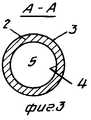
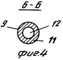
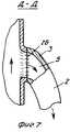
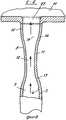
На фиг.1 показано сердце человека, вид спереди; на фиг.2 - увеличенный частичный разрез трансплантата, вид сверху; на фиг.3 - разрез А-А на фиг.2; на фиг.4 - разрез Б-Б на фиг.2; на фиг.5 - разрез В-В на фиг.2; на фиг.6 - разрез Г-Г на фиг.2; на фиг.7 - разрез D-D фиг.1; на фиг.8 - разрез Е-Е на фиг. 1; на фиг.9 - разрез Ж-Ж на фиг.1; на фиг.10 - вид сверху с частичным разрезом трансплантата и регулируемого ограничителя потока крови для него. Figure 1 shows the human heart, front view; figure 2 is an enlarged partial section of the graft, top view; figure 3 is a section aa in figure 2; figure 4 is a section bB in figure 2; figure 5 is a section bb in figure 2; in Fig.6 is a section GG in Fig.2; Fig.7 is a section D-D of Fig.1; on Fig - section EE in fig. 1; in Fig.9 - section FJ in Fig.1; figure 10 is a top view with a partial section of the transplant and the adjustable blood flow restrictor for him.
Протез кровеносного сосуда 1 состоит из корпуса 2, выполненного в виде удлиненного элемента, имеющего U-образную форму и непрерывный канал для подачи крови. Корпус 2 имеет непрерывную цилиндрическую стенку 3 с внутренней поверхностью 4, образующей удлиненный продольный канал 5. Трубчатый элемент имеет входное отверстие 6 (аортное) и выходное отверстие 7 (артериальное). Основной (в общем U-образный) ствол 8 направлен от входного отверстия 6 в суженную секцию 9. Суженная секция 9 соединена с дальней концевой секцией 10. Предпочтительно, суженная секция 9 находится примерно на расстоянии 2-5 см от выходного отверстия 7, когда она закреплена на сердечной ткани. Суженная секция 9 имеет цилиндрическую стенку 11, выполненную за одно целое с цилиндрической стенкой 3 основного ствола 8 и артериальной концевой секции 10. Стенка 11 окружает горловой проход 12, поперечное сечение которого значительно меньше поперечного сечения канала 5. Предпочтительно, площадь поперечного сечения канала 5 более чем в 4 раза больше поперечного сечения горлового канала 12. Цилиндрическая стенка 11 присоединена к стенке 3 с помощью сходящейся конической стеночной части 13, которая направляет поток крови в канал 12. Противоположные концы стенки 11 соединяются с расходящейся конической стеночной частью 14, образующей части артериальной концевой секции 10. Стеночной часть 14 окружает выпускной канал 15, направленный к дальнему выпускному концу 7. Площадь поперечного сечения выпускного канала 15 по существу аналогична площади поперечного сечения канала 5 основного ствола. Однако поперечное сечение выпускного канала 15 может быть больше поперечного сечения канала 5. Каждая коническая стеночная часть 13 и 14 имеет продольный отрезок и внутреннюю стеночную поверхность, которая имеет плавную конусность для сведения к минимуму турбулентности потока крови. Предпочтительно, цилиндрическая стенка 11, окружающая канал 12, имеет продольный отрезок, который короче продольного отрезка стеночных частей 13 и 14. Причем может быть использовано другое соотношение размеров отрезков. Чем длиннее суженная секция 9, тем больше перепад давления для данной площади поперечного сечения канала 12. Канал 15 образует камеру, в которой скорость потока крови и давление крови понижаются перед подачей в предсердие сердца. Дальняя концевая секция 10 имеет такой размер, который позволяет легко крепить ее к сердечным тканям или сосуду, принимающему кровь. The prosthesis of the
Корпус 2 представляет собой трубчатую конструкцию, которая (предпочтительно) изготавливается из пуповины человека. Предварительно пуповина изгибается и ей придается конусная форма для получения нужной суженной секции 9. Трубчатая конструкция может быть изготовлена из других тканей, включая, но не ограничиваясь, бычьей сонной артерией, овечьим подкожным трубчатым элементом, кошачьим пищеводом или кишечником. Для сосудистого трансплантата можно использовать другие трубчатые конструкции, например политетрафторэтиленовые трубки или другие синтетические трубки. The
Средство ограничения 16 потока крови (фиг.10) установлено на корпусе 2 рядом с концевой секцией 10 для ограничения потока крови и для поддержания непрерывного и адекватного потока крови с заданным давлением таким образом, чтобы снабжать одну или несколько коронарных артерий. Кроме того, средство ограничения 16 используется для усиления трубчатого элемента, образующего суженный канал. Средство ограничения представляет собой зажим, который состоит из первого элемента 17, соединенного с возможностью регулирования со вторым элементом 18 с помощью пары самозапирающихся винтов 19 и 20. Элемент 17 имеет изогнутую наружу центральную секцию, расположенную вокруг арочного сектора элемента 2. Второй элемент 18 имеет изогнутую наружу в противоположном направлении центральную секцию, обращенную к изогнутой центральной секции и входящую в сцепление с арочным сегментом элемента 2. Винты 10 и 20 могут регулироваться для перемещения первого и второго элементов 17 и 18 в направлении друг друга для регулирования размера суженной секции 9 с целью регулирования расхода потока крови и давления крови. Цилиндрическая вставка заданного сечения используется для образования суженного канала нужного размера или сечения. Вставка вставляется в удаленную концевую секцию корпуса 2. Средство ограничения 16 установлено на концевой секцией и прижимается к корпусу 2. Изогнутые центральные секции перемещаются в направлении одна к другой и обжимают стенку корпуса 2 вокруг вставки. Эта вставка затем удаляется из корпуса 2. Ограничитель поддерживает заданное сечение канала. Для сосудистого трансплантата можно использовать другие материалы и комбинации материалов. В варианте выполнения сосуда. Суженная секция 10 усиливается втулкой 23 для поддержания неизменными сечения и длины канала в течение длительного периода времени. Таким образом обеспечивается непрерывная и регулируемая подача потока крови через сосудистый трансплантат, а также давление крови в канале поддерживается на уровне, достаточном для питания коронарных ветвей ствола. Втулка 23 может представлять собой трубчатый элемент, армированный волокном, из металла, пластмассы или углеродных волокон, выполненных в виде сетки, окружающей суженную секцию 9. Можно использовать ленту или нить. Втулку 23 можно приклеить или закрепить другим способом на наружной поверхности суженной секции 9. Упрочняющая конструкция может быть включена и в материал суженной секции 9. Кроме того, толщина стенки суженной части может быть увеличена для ее упрочнения. The blood flow restriction 16 (FIG. 10) is installed on the
Устройство работает следующим образом. The device operates as follows.
Протез кровеносного сосуда располагается рядом с сердцем 24. Корпус 2 опускается в направлении средней части передней поверхности сердца, затем проходит вокруг задней поверхности и опускается в направлении правого предсердия. Суженная секция 9 и артериальная концевая секция 10 расположены рядом с предсеpдием. Входное отверстие 6 корпуса 2 (фиг.7) имплантировано в отверстие аорты и анастомозировано с отверстием с помощью швов 26. Выпускной или артериальный конец 10 (фиг.8) имплантирован в отверстие 27 в сердце 24, сообщающееся с предсердием 25, и анастомозирован с отверстием с помощью швов. Кровь непрерывно поступает через канал 5 корпуса 2 перепада давления крови между аортой 28 и предсердием 25. Суженный канал 12 предотвращает прохождение избыточного потока крови через канал 5. Концевая секция 10 трубчатого элемента 2 может быть анастомозирована с левым предсердием 29 в силу чего кровь поступает из аорты 28 через канал 5 и корпус 2 в левое предсердие 29. Корпус 2 трансплантата расположен рядом с одной или несколькими коронарными ветвями 30. Хирург имеет выбор для анастомоза и поэтому снабжает кровью одну или несколько коронарных ветвей вдоль расположения трансплантата, который (фиг.9) анастомозируется к коронарной ветви 30 с помощью швов. Цилиндрическая стенка 3 с отверстием 32 служит для подачи крови из канала 5 в канал 33 коронарной артерии. Суженный канал 12, расположенный рядом с артериальным концом трансплантата, позволяет снабжать коронарные артерии достаточным количеством крови под давлением, составляющим несколько мм рт. ст. от аортного давления крови. Поток крови в сужении 12 является ламинарным и остается ламинарным при прохождении через канал в предсердие 25. В трансплантате образуется минимальная турбулентность потока крови. Внутренняя поверхность 4 трубчатого элемента 2 выполнена гладкой и непрерывной. Она не содержит никаких азотистых соединений, которые могут вызвать застаивание или коагулирование крови. The prosthesis of the blood vessel is located next to the
Необходимый поток крови в канале 5 трансплантата обеспечивается с помощью подбора диаметра аортного анастомоза и составляет примерно 2500 мл/мин. Испытания показывают, что использование трубчатого трансплантата диаметром 5 мм с моделированным расходом аортного потока в примерно 6000 мл/мин и давлением 100 мм рт.ст. обеспечивает прохождение примерно 500 мл/мин через 2 мм сужение в правой артерии. Так как минутный объем сердца ограничен только венозным возвратом, левый желудочек будет иметь дополнительную нагрузку примерно в 8% . Для каждой коронарной артерии, питаемой кровью, требуется примерно 50-150 мл/мин крови для соответствующей перфузии. Так как поток крови, проходящей через несуженный 5 мм трансплантат анастомозированный к аорте (при расходе крови в 6000 мл/мин) обеспечивает подачу крови более 2000 мл/мин, т.е. имеется достаточно количество крови для питания до 10 коронарных ветвей, через каждую из которых проходит 150 мм/мин. Расчет потока крови, проходящего через канал 12, показывает число Рейнольдса в 500-1000. В каналах 5 и 12 поток крови является ламинарным. The necessary blood flow in the
Трансплантаты изобретения можно использовать для подачи крови при периферийной реваскуляризации нижней конечностей. Например, трансплантат может устанавливаться между наиболее удаленным артериальным анастомозом и подколенной венной или одной из ее основных ветвей. Источником крови может служить бедренная артерия, а анастомоз накладывается на подколенную артерию и/или ее удаленные ветви, переднюю большеберцовую, заднюю большеберцовую или малоберцовую артерии. Канал ограничения потока крови или горловой канал, расположенный между этими артериями и удаленным концом трансплантата, регулирует поток крови в трансплантате. Регулирование потока позволяет обеспечить необходимое снабжение кровью этих артерий, а также подачу непрерывного потока крови для сохранения проходимости трансплантата. Transplants of the invention can be used to supply blood for peripheral revascularization of the lower extremities. For example, a graft may be placed between the most distant arterial anastomosis and the popliteal vein or one of its main branches. The femoral artery can serve as a blood source, and the anastomosis is superimposed on the popliteal artery and / or its remote branches, the anterior tibial, posterior tibial or fibular arteries. The blood flow restriction channel or the throat channel located between these arteries and the distal end of the graft regulates the blood flow in the graft. Flow control allows you to provide the necessary blood supply to these arteries, as well as a continuous flow of blood to maintain transplant patency.
Claims (11)
Translated fromRussianApplications Claiming Priority (5)
| Application Number | Priority Date | Filing Date | Title |
|---|---|---|---|
| US448955 | 1982-12-13 | ||
| US06/448,955US4546499A (en) | 1982-12-13 | 1982-12-13 | Method of supplying blood to blood receiving vessels |
| US489798 | 1983-04-29 | ||
| US06/489,798US4562597A (en) | 1982-12-13 | 1983-04-29 | Method of supplying blood to blood receiving vessels |
| PCT/US1983/001932WO1984002266A1 (en) | 1982-12-13 | 1983-12-08 | Vascular graft and blood supply method |
Publications (1)
| Publication Number | Publication Date |
|---|---|
| RU2023438C1true RU2023438C1 (en) | 1994-11-30 |
Family
ID=27035549
Family Applications (1)
| Application Number | Title | Priority Date | Filing Date |
|---|---|---|---|
| SU843781696ARU2023438C1 (en) | 1982-12-13 | 1984-08-10 | Blood vessel prosthesis |
Country Status (23)
| Country | Link |
|---|---|
| US (3) | US4546499A (en) |
| EP (1) | EP0128215B1 (en) |
| JP (1) | JPS60500244A (en) |
| AT (1) | ATE51750T1 (en) |
| AU (2) | AU572819B2 (en) |
| BE (1) | BE900533A (en) |
| BR (1) | BR8307628A (en) |
| CA (1) | CA1238153A (en) |
| DE (1) | DE3390385C2 (en) |
| DK (1) | DK385384A (en) |
| ES (1) | ES284576Y (en) |
| FI (1) | FI82371C (en) |
| GB (2) | GB2141939B (en) |
| GR (1) | GR79165B (en) |
| IL (1) | IL70370A (en) |
| IT (1) | IT1169976B (en) |
| MX (1) | MX159806A (en) |
| NO (1) | NO159338C (en) |
| RU (1) | RU2023438C1 (en) |
| SE (1) | SE458660B (en) |
| UA (1) | UA7994A (en) |
| WO (1) | WO1984002266A1 (en) |
| ZA (1) | ZA839229B (en) |
Cited By (4)
| Publication number | Priority date | Publication date | Assignee | Title |
|---|---|---|---|---|
| RU2179003C2 (en)* | 1995-11-10 | 2002-02-10 | Эндогэд Рисерч ПТИ Лимитед | Method for carrying out branched artery transplantation inside of the lumen |
| RU2205620C2 (en)* | 2001-03-02 | 2003-06-10 | Республиканская офтальмологическая клиническая больница | Transplant for extrascleral revascularization |
| RU2466695C1 (en)* | 2011-07-22 | 2012-11-20 | Закрытое Акционерное Общество Научно-Производственное Предприятие "Мединж" | Valve-containing pulmonary arterial graft |
| RU2492838C2 (en)* | 2008-04-11 | 2013-09-20 | Фин-Керамика Фаэнца С.п.А. | Method of perfusion of transplant from biocompatible material with liquid and set for perfusion |
Families Citing this family (175)
| Publication number | Priority date | Publication date | Assignee | Title |
|---|---|---|---|---|
| US4546499A (en)* | 1982-12-13 | 1985-10-15 | Possis Medical, Inc. | Method of supplying blood to blood receiving vessels |
| US4909979A (en)* | 1983-03-24 | 1990-03-20 | Possis Medical, Inc. | Method for making a vascular graft |
| AU592772B2 (en)* | 1984-09-05 | 1990-01-25 | Vaso Products Australia Pty. Limited | Control of blood flow |
| EP0200286A3 (en)* | 1985-02-28 | 1987-01-14 | Quotidian No. 100 Pty. Limited | Control of blood flow |
| EP0331725B1 (en)* | 1987-08-31 | 1994-12-28 | Acculase, Inc. | Rare gas-halogen excimer laser |
| US4840940A (en)* | 1987-10-21 | 1989-06-20 | Sottiurai Vikrom S | Method for reducing the occurrence of distal anastomotic intimal hyperplasia using fractionated heparin |
| US7033383B1 (en) | 1991-07-03 | 2006-04-25 | Cardiothoracic Systems, Inc. | Endoscopic bypass grafting method utilizing an inguinal approach |
| US20060161173A1 (en)* | 1991-07-03 | 2006-07-20 | Maginot Thomas J | Endoscopic bypass grafting method utilizing an inguinal approach |
| US7597697B1 (en)* | 1991-07-03 | 2009-10-06 | Boston Scientific Scimed, Inc. | Bypass grafting method |
| US5211683A (en)* | 1991-07-03 | 1993-05-18 | Maginot Thomas J | Method of implanting a graft prosthesis in the body of a patient |
| US5304220A (en)* | 1991-07-03 | 1994-04-19 | Maginot Thomas J | Method and apparatus for implanting a graft prosthesis in the body of a patient |
| US5756035A (en)* | 1991-08-01 | 1998-05-26 | Polymedica Industries, Inc. | Method of making an access graft and a vascular prosthesis |
| GB9116563D0 (en)* | 1991-08-01 | 1991-09-18 | Newtec Vascular Products Ltd | Vascular prosthesis ii |
| US5662713A (en)* | 1991-10-09 | 1997-09-02 | Boston Scientific Corporation | Medical stents for body lumens exhibiting peristaltic motion |
| US5876445A (en)* | 1991-10-09 | 1999-03-02 | Boston Scientific Corporation | Medical stents for body lumens exhibiting peristaltic motion |
| US5211658A (en)* | 1991-11-05 | 1993-05-18 | New England Deaconess Hospital Corporation | Method and device for performing endovascular repair of aneurysms |
| CA2146156C (en)* | 1992-10-13 | 2004-11-30 | Erik Andersen | Medical stents for body lumens exhibiting peristaltic motion |
| US5409019A (en)* | 1992-10-30 | 1995-04-25 | Wilk; Peter J. | Coronary artery by-pass method |
| US5429144A (en)* | 1992-10-30 | 1995-07-04 | Wilk; Peter J. | Coronary artery by-pass method |
| US5425765A (en) | 1993-06-25 | 1995-06-20 | Tiefenbrun; Jonathan | Surgical bypass method |
| US5632772A (en)* | 1993-10-21 | 1997-05-27 | Corvita Corporation | Expandable supportive branched endoluminal grafts |
| US5480424A (en)* | 1993-11-01 | 1996-01-02 | Cox; James L. | Heart valve replacement using flexible tubes |
| WO1997024083A1 (en)* | 1993-11-01 | 1997-07-10 | Cox James L | Method of replacing heart valves using flexible tubes |
| US5713950A (en)* | 1993-11-01 | 1998-02-03 | Cox; James L. | Method of replacing heart valves using flexible tubes |
| US5476506A (en)* | 1994-02-08 | 1995-12-19 | Ethicon, Inc. | Bi-directional crimped graft |
| CA2147547C (en) | 1994-08-02 | 2006-12-19 | Peter J. Schmitt | Thinly woven flexible graft |
| US5591226A (en)* | 1995-01-23 | 1997-01-07 | Schneider (Usa) Inc. | Percutaneous stent-graft and method for delivery thereof |
| US5683449A (en) | 1995-02-24 | 1997-11-04 | Marcade; Jean Paul | Modular bifurcated intraluminal grafts and methods for delivering and assembling same |
| DE19508129C2 (en)* | 1995-03-08 | 1997-02-13 | Jan Dr Med Menke | Blood flow adjustment device for optional external constriction and expansion of the blood flow cross section of a blood vessel |
| ATE440559T1 (en)* | 1995-10-13 | 2009-09-15 | Medtronic Vascular Inc | DEVICE FOR INTERSTITIAL TRANSVASCULAR PROCEDURES |
| DE69633411T2 (en)* | 1995-10-13 | 2005-10-20 | Transvascular, Inc., Menlo Park | METHOD AND DEVICE FOR PREVENTING ARTERIAL ATTRACTIONS AND / OR FOR CARRYING OUT OTHER TRANSVASCULAR INTERVENTIONS |
| US20080221668A1 (en)* | 1995-11-13 | 2008-09-11 | Boston Scientific Corp. | Expandable supportive branched endoluminal grafts |
| JP2750569B2 (en)* | 1995-12-07 | 1998-05-13 | 幸夫 堀口 | Intravascular blood flow regulator and artificial blood vessel for bypass |
| AU733341B2 (en) | 1996-02-02 | 2001-05-10 | Transvascular, Inc. | A device, system and method for interstitial transvascular intervention |
| DE19604881A1 (en)* | 1996-02-10 | 1997-08-14 | Klaus Prof Dr Ing Affeld | Mechanical prosthetic heart valve |
| CA2245897C (en)* | 1996-02-28 | 2004-12-14 | Impra, Inc. | Flanged graft for end-to-side anastomosis |
| US6273912B1 (en) | 1996-02-28 | 2001-08-14 | Impra, Inc. | Flanged graft for end-to-side anastomosis |
| US6190590B1 (en)* | 1996-02-28 | 2001-02-20 | Impra, Inc. | Apparatus and method for making flanged graft for end-to-side anastomosis |
| US5782905A (en)* | 1996-05-03 | 1998-07-21 | Zuli Holdings Ltd. | Endovascular device for protection of aneurysm |
| US5662124A (en)* | 1996-06-19 | 1997-09-02 | Wilk Patent Development Corp. | Coronary artery by-pass method |
| US5755682A (en)* | 1996-08-13 | 1998-05-26 | Heartstent Corporation | Method and apparatus for performing coronary artery bypass surgery |
| JP2001502205A (en)* | 1996-10-07 | 2001-02-20 | ポシス メディカル インコーポレイテッド | Vascular graft |
| US5941908A (en)* | 1997-04-23 | 1999-08-24 | Vascular Science, Inc. | Artificial medical graft with a releasable retainer |
| US6035856A (en)* | 1997-03-06 | 2000-03-14 | Scimed Life Systems | Percutaneous bypass with branching vessel |
| US6155264A (en)* | 1997-03-06 | 2000-12-05 | Scimed Life Systems, Inc. | Percutaneous bypass by tunneling through vessel wall |
| US6026814A (en) | 1997-03-06 | 2000-02-22 | Scimed Life Systems, Inc. | System and method for percutaneous coronary artery bypass |
| US7708769B1 (en) | 1997-03-13 | 2010-05-04 | United States Surgical Corporation | Graft attachment assembly |
| WO1998046115A2 (en)* | 1997-04-11 | 1998-10-22 | Transvascular, Inc. | Methods and apparatus for transmyocardial direct coronary revascularization |
| GB9709967D0 (en)* | 1997-05-17 | 1997-07-09 | Harris Peter L | Prosthetic grafts |
| US6092526A (en)* | 1997-06-19 | 2000-07-25 | Scimed Life Systems, Inc. | Percutaneous chamber-to-artery bypass |
| US6443158B1 (en) | 1997-06-19 | 2002-09-03 | Scimed Life Systems, Inc. | Percutaneous coronary artery bypass through a venous vessel |
| US6213126B1 (en) | 1997-06-19 | 2001-04-10 | Scimed Life Systems, Inc. | Percutaneous artery to artery bypass using heart tissue as a portion of a bypass conduit |
| US5908029A (en)* | 1997-08-15 | 1999-06-01 | Heartstent Corporation | Coronary artery bypass with reverse flow |
| US6063114A (en)* | 1997-09-04 | 2000-05-16 | Kensey Nash Corporation | Connector system for vessels, ducts, lumens or hollow organs and methods of use |
| US6187033B1 (en) | 1997-09-04 | 2001-02-13 | Meadox Medicals, Inc. | Aortic arch prosthetic graft |
| US5922022A (en)* | 1997-09-04 | 1999-07-13 | Kensey Nash Corporation | Bifurcated connector system for coronary bypass grafts and methods of use |
| US6102941A (en)* | 1997-10-06 | 2000-08-15 | Heartstent Corporation | Transmyocardial implant with coronary ingrowth |
| US5984956A (en)* | 1997-10-06 | 1999-11-16 | Heartstent Corporation | Transmyocardial implant |
| US6371982B2 (en) | 1997-10-09 | 2002-04-16 | St. Jude Medical Cardiovascular Group, Inc. | Graft structures with compliance gradients |
| US6251418B1 (en)* | 1997-12-18 | 2001-06-26 | C.R. Bard, Inc. | Systems and methods for local delivery of an agent |
| US6197324B1 (en) | 1997-12-18 | 2001-03-06 | C. R. Bard, Inc. | System and methods for local delivery of an agent |
| US6048362A (en)* | 1998-01-12 | 2000-04-11 | St. Jude Medical Cardiovascular Group, Inc. | Fluoroscopically-visible flexible graft structures |
| US6250305B1 (en) | 1998-01-20 | 2001-06-26 | Heartstent Corporation | Method for using a flexible transmyocardial implant |
| US6214041B1 (en) | 1998-01-20 | 2001-04-10 | Heartstent Corporation | Transmyocardial implant with septal perfusion |
| US6007576A (en)* | 1998-02-06 | 1999-12-28 | Mcclellan; Scott B. | End to side anastomic implant |
| US20020144696A1 (en) | 1998-02-13 | 2002-10-10 | A. Adam Sharkawy | Conduits for use in placing a target vessel in fluid communication with a source of blood |
| WO1999040868A1 (en)* | 1998-02-13 | 1999-08-19 | Ventrica, Inc. | Methods and devices providing transmyocardial blood flow to the arterial vascular system of the heart |
| US6808498B2 (en) | 1998-02-13 | 2004-10-26 | Ventrica, Inc. | Placing a guide member into a heart chamber through a coronary vessel and delivering devices for placing the coronary vessel in communication with the heart chamber |
| US6651670B2 (en)* | 1998-02-13 | 2003-11-25 | Ventrica, Inc. | Delivering a conduit into a heart wall to place a coronary vessel in communication with a heart chamber and removing tissue from the vessel or heart wall to facilitate such communication |
| US7027398B2 (en)* | 2001-04-12 | 2006-04-11 | General Instrument Corporation | Method and apparatus for monitoring voice conversations from customer premises equipment |
| US6235054B1 (en) | 1998-02-27 | 2001-05-22 | St. Jude Medical Cardiovascular Group, Inc. | Grafts with suture connectors |
| US6325813B1 (en) | 1998-08-18 | 2001-12-04 | Scimed Life Systems, Inc. | Method and apparatus for stabilizing vascular wall |
| US6254564B1 (en) | 1998-09-10 | 2001-07-03 | Percardia, Inc. | Left ventricular conduit with blood vessel graft |
| US6689121B1 (en) | 1998-09-24 | 2004-02-10 | C. R. Bard, Inc. | Systems and methods for treating ischemia |
| US6248112B1 (en) | 1998-09-30 | 2001-06-19 | C. R. Bard, Inc. | Implant delivery system |
| US6458092B1 (en) | 1998-09-30 | 2002-10-01 | C. R. Bard, Inc. | Vascular inducing implants |
| US6432126B1 (en)* | 1998-09-30 | 2002-08-13 | C.R. Bard, Inc. | Flexible vascular inducing implants |
| US6692520B1 (en) | 1998-12-15 | 2004-02-17 | C. R. Bard, Inc. | Systems and methods for imbedded intramuscular implants |
| US7025773B2 (en) | 1999-01-15 | 2006-04-11 | Medtronic, Inc. | Methods and devices for placing a conduit in fluid communication with a target vessel |
| US7578828B2 (en)* | 1999-01-15 | 2009-08-25 | Medtronic, Inc. | Methods and devices for placing a conduit in fluid communication with a target vessel |
| US6409697B2 (en)* | 1999-05-04 | 2002-06-25 | Heartstent Corporation | Transmyocardial implant with forward flow bias |
| US6182668B1 (en) | 1999-05-13 | 2001-02-06 | Heartstent Corporation | Transmyocardial implant with induced tissue flap |
| US6986784B1 (en) | 1999-05-14 | 2006-01-17 | C. R. Bard, Inc. | Implant anchor systems |
| US6855160B1 (en) | 1999-08-04 | 2005-02-15 | C. R. Bard, Inc. | Implant and agent delivery device |
| US6253768B1 (en)* | 1999-08-04 | 2001-07-03 | Percardia, Inc. | Vascular graft bypass |
| US20080018016A1 (en)* | 1999-09-10 | 2008-01-24 | Rapacki Alan R | Manufacturing conduits for use in placing a target vessel in fluid communication with a source of blood |
| US6635214B2 (en)* | 1999-09-10 | 2003-10-21 | Ventrica, Inc. | Manufacturing conduits for use in placing a target vessel in fluid communication with a source of blood |
| US6592567B1 (en) | 1999-12-07 | 2003-07-15 | Chf Solutions, Inc. | Kidney perfusion catheter |
| US8092511B2 (en) | 2000-03-03 | 2012-01-10 | Endovascular Technologies, Inc. | Modular stent-graft for endovascular repair of aortic arch aneurysms and dissections |
| US6814752B1 (en) | 2000-03-03 | 2004-11-09 | Endovascular Technologies, Inc. | Modular grafting system and method |
| IL153753A0 (en)* | 2002-12-30 | 2003-07-06 | Neovasc Medical Ltd | Varying-diameter vascular implant and balloon |
| US6953476B1 (en)* | 2000-03-27 | 2005-10-11 | Neovasc Medical Ltd. | Device and method for treating ischemic heart disease |
| US7666221B2 (en) | 2000-05-01 | 2010-02-23 | Endovascular Technologies, Inc. | Lock modular graft component junctions |
| US7232421B1 (en) | 2000-05-12 | 2007-06-19 | C. R. Bard, Inc. | Agent delivery systems |
| US7204847B1 (en) | 2000-07-28 | 2007-04-17 | C. R. Bard, Inc. | Implant anchor systems |
| DE20100443U1 (en) | 2001-01-11 | 2001-06-28 | Fresenius Medical Care Deutschland GmbH, 61352 Bad Homburg | Arteriovenous vascular prosthesis |
| US20020123786A1 (en)* | 2001-03-02 | 2002-09-05 | Ventrica, Inc. | Methods and devices for bypassing an obstructed target vessel by placing the vessel in communication with a heart chamber containing blood |
| US6702835B2 (en) | 2001-09-07 | 2004-03-09 | Core Medical, Inc. | Needle apparatus for closing septal defects and methods for using such apparatus |
| US20060052821A1 (en) | 2001-09-06 | 2006-03-09 | Ovalis, Inc. | Systems and methods for treating septal defects |
| US6776784B2 (en) | 2001-09-06 | 2004-08-17 | Core Medical, Inc. | Clip apparatus for closing septal defects and methods of use |
| CA2462509A1 (en) | 2001-10-04 | 2003-04-10 | Neovasc Medical Ltd. | Flow reducing implant |
| US6942672B2 (en) | 2001-10-23 | 2005-09-13 | Vascor, Inc. | Method and apparatus for attaching a conduit to the heart or a blood vessel |
| EP2075014B9 (en) | 2002-05-24 | 2012-02-01 | Angiotech International Ag | Compositions and methods for coating medical implants |
| US20030181843A1 (en)* | 2002-06-11 | 2003-09-25 | Scout Medical Technologies, Llc | Device and method providing arterial blood flow for perfusion of ischemic myocardium |
| WO2004014257A1 (en)* | 2002-08-08 | 2004-02-19 | Neovasc Medical Ltd. | Geometric flow regulator |
| WO2004014474A1 (en)* | 2002-08-08 | 2004-02-19 | Neovasc Medical Ltd. | Flow reducing implant |
| US8535370B1 (en) | 2003-01-23 | 2013-09-17 | Endovascular Technologies, Inc. | Radiopaque markers for endovascular graft alignment |
| ATE511875T1 (en)* | 2003-04-23 | 2011-06-15 | Interrad Medical Inc | DIALYSE VALVE |
| US20040215125A1 (en)* | 2003-04-27 | 2004-10-28 | Brown Donald W. | Bifurcated graft for dialysis |
| US20040228411A1 (en)* | 2003-05-12 | 2004-11-18 | Sony Corporation | Method and system for decoder clock control in presence of jitter |
| US7566317B1 (en)* | 2003-07-07 | 2009-07-28 | Stanley Batiste | A-V dialysis graft |
| US7011643B2 (en) | 2003-08-05 | 2006-03-14 | Cabg Medical, Inc. | Grafted network incorporating a multiple channel fluid flow connector |
| US6991615B2 (en)* | 2003-08-05 | 2006-01-31 | Cabg Medical, Inc. | Grafted network incorporating a multiple channel fluid flow connector |
| US6986751B2 (en)* | 2003-08-05 | 2006-01-17 | Cabg Medical, Inc. | Grafted network incorporating a multiple channel fluid flow connector |
| US7235083B1 (en) | 2003-09-10 | 2007-06-26 | Endovascular Technologies, Inc. | Methods and devices for aiding in situ assembly of repair devices |
| US20050288618A1 (en)* | 2004-06-24 | 2005-12-29 | Scimed Life Systems, Inc. | Myocardial treatment apparatus and method |
| US7828814B2 (en) | 2004-08-27 | 2010-11-09 | Rox Medical, Inc. | Device and method for establishing an artificial arterio-venous fistula |
| US9706997B2 (en)* | 2004-08-27 | 2017-07-18 | Rox Medical, Inc. | Device and method for establishing an artificial arterio-venous fistula |
| US20060047337A1 (en) | 2004-08-27 | 2006-03-02 | Brenneman Rodney A | Device and method for establishing an artificial arterio-venous fistula |
| US8226592B2 (en)* | 2004-12-15 | 2012-07-24 | Rox Medical, Inc. | Method of treating COPD with artificial arterio-venous fistula and flow mediating systems |
| DE102005003632A1 (en) | 2005-01-20 | 2006-08-17 | Fraunhofer-Gesellschaft zur Förderung der angewandten Forschung e.V. | Catheter for the transvascular implantation of heart valve prostheses |
| EP1693025A1 (en)* | 2005-02-17 | 2006-08-23 | Universität Zürich | Method of manufacturing a tissue-engineered prosthesis |
| US20060195178A1 (en)* | 2005-02-28 | 2006-08-31 | Stephen West | Aneurismal sack deflator |
| AU2006259415B2 (en)* | 2005-06-15 | 2012-08-30 | Massachusetts Institute Of Technology | Amine-containing lipids and uses thereof |
| US8709069B2 (en) | 2005-07-01 | 2014-04-29 | C. R. Bard, Inc. | Flanged graft with trim lines |
| US8579936B2 (en) | 2005-07-05 | 2013-11-12 | ProMed, Inc. | Centering of delivery devices with respect to a septal defect |
| US7846179B2 (en) | 2005-09-01 | 2010-12-07 | Ovalis, Inc. | Suture-based systems and methods for treating septal defects |
| US7568753B2 (en)* | 2006-06-15 | 2009-08-04 | Mattel, Inc. | Children's ride-on vehicles with reconfigured bodies and methods for forming the same |
| SE530226C2 (en)* | 2006-08-15 | 2008-04-01 | Gestamp Hardtech Ab | Bumper beam for vehicles |
| US20080051879A1 (en)* | 2006-08-23 | 2008-02-28 | Cook Incorporated | Methods of treating venous valve related conditions with a flow-modifying implantable medical device |
| US7896915B2 (en) | 2007-04-13 | 2011-03-01 | Jenavalve Technology, Inc. | Medical device for treating a heart valve insufficiency |
| US20100280598A1 (en)* | 2007-12-27 | 2010-11-04 | C.R. Bard, Inc. | Vascular graft prosthesis having a reinforced margin for enhanced anastomosis |
| EP2237742A4 (en)* | 2007-12-31 | 2015-02-25 | Bard Inc C R | Vascular graft prosthesis with selective flow reduction |
| BR112012021347A2 (en) | 2008-02-26 | 2019-09-24 | Jenavalve Tecnology Inc | stent for positioning and anchoring a valve prosthesis at an implantation site in a patient's heart |
| US9044318B2 (en) | 2008-02-26 | 2015-06-02 | Jenavalve Technology Gmbh | Stent for the positioning and anchoring of a valvular prosthesis |
| US20100130835A1 (en)* | 2008-09-30 | 2010-05-27 | Rox Medical, Inc. | Methods for screening and treating patients with compromised cardiopulmonary function |
| CN104910025B (en) | 2008-11-07 | 2019-07-16 | 麻省理工学院 | Alkamine lipid and its purposes |
| KR101275992B1 (en)* | 2009-01-16 | 2013-06-17 | 에이비비 테크놀로지 아게 | Voltage source converter with redundant switching cells via mechanical switches being closed pyrotechnically |
| HUE038039T2 (en) | 2009-12-01 | 2018-09-28 | Translate Bio Inc | Delivery of mrna for the augmentation of proteins and enzymes in human genetic diseases |
| US10856978B2 (en) | 2010-05-20 | 2020-12-08 | Jenavalve Technology, Inc. | Catheter system |
| WO2011147849A1 (en) | 2010-05-25 | 2011-12-01 | Jenavalve Technology Inc. | Prosthetic heart valve and transcatheter delivered endoprosthesis comprising a prosthetic heart valve and a stent |
| EP2609135A4 (en) | 2010-08-26 | 2015-05-20 | Massachusetts Inst Technology | POLY (BETA-AMINO ALCOHOLS), THEIR PREPARATION AND USES THEREOF |
| EP2691443B1 (en) | 2011-03-28 | 2021-02-17 | Massachusetts Institute of Technology | Conjugated lipomers and uses thereof |
| PL2717893T3 (en) | 2011-06-08 | 2019-12-31 | Translate Bio, Inc. | Lipid nanoparticle compositions and methods for mRNA delivery |
| WO2013185067A1 (en) | 2012-06-08 | 2013-12-12 | Shire Human Genetic Therapies, Inc. | Nuclease resistant polynucleotides and uses thereof |
| AU2014236396A1 (en) | 2013-03-14 | 2015-08-13 | Shire Human Genetic Therapies, Inc. | Methods for purification of messenger RNA |
| IL290953B2 (en) | 2013-03-14 | 2024-01-01 | Ethris Gmbh | Cftr mrna compositions and related methods and uses |
| US9315472B2 (en) | 2013-05-01 | 2016-04-19 | Massachusetts Institute Of Technology | 1,3,5-triazinane-2,4,6-trione derivatives and uses thereof |
| CN105491978A (en) | 2013-08-30 | 2016-04-13 | 耶拿阀门科技股份有限公司 | Radially collapsible frame for a prosthetic valve and method for manufacturing such a frame |
| KR102096796B1 (en) | 2013-10-22 | 2020-05-27 | 샤이어 휴먼 지네틱 테라피즈 인크. | Lipid formulations for delivery of messenger rna |
| CN106413811A (en) | 2013-10-22 | 2017-02-15 | 夏尔人类遗传性治疗公司 | Mrna therapy for argininosuccinate synthetase deficiency |
| EA201992208A1 (en) | 2013-10-22 | 2020-07-31 | Транслейт Био, Инк. | TREATMENT OF PHENYLKETONURIA USING mRNA |
| SG11201608725YA (en) | 2014-04-25 | 2016-11-29 | Shire Human Genetic Therapies | Methods for purification of messenger rna |
| CA3211902A1 (en) | 2014-05-30 | 2015-12-03 | Translate Bio, Inc. | Biodegradable lipids for delivery of nucleic acids |
| PE20171238A1 (en) | 2014-06-24 | 2017-08-24 | Shire Human Genetic Therapies | STEREOCHEMICALLY ENRICHED COMPOSITIONS FOR NUCLEIC ACIDS ADMINISTRATION |
| US9840479B2 (en) | 2014-07-02 | 2017-12-12 | Massachusetts Institute Of Technology | Polyamine-fatty acid derived lipidoids and uses thereof |
| US10667931B2 (en)* | 2014-07-20 | 2020-06-02 | Restore Medical Ltd. | Pulmonary artery implant apparatus and methods of use thereof |
| EP3270825B1 (en) | 2015-03-20 | 2020-04-22 | JenaValve Technology, Inc. | Heart valve prosthesis delivery system |
| CA2980316A1 (en) | 2015-03-24 | 2016-09-29 | Osiris Therapeutics, Inc. | Compositions comprising meniscal tissues and uses thereof |
| US10709555B2 (en) | 2015-05-01 | 2020-07-14 | Jenavalve Technology, Inc. | Device and method with reduced pacemaker rate in heart valve replacement |
| WO2017195125A1 (en) | 2016-05-13 | 2017-11-16 | Jenavalve Technology, Inc. | Heart valve prosthesis delivery system and method for delivery of heart valve prosthesis with introducer sheath and loading system |
| US11771434B2 (en) | 2016-09-28 | 2023-10-03 | Restore Medical Ltd. | Artery medical apparatus and methods of use thereof |
| WO2018138658A1 (en) | 2017-01-27 | 2018-08-02 | Jenavalve Technology, Inc. | Heart valve mimicry |
| WO2018157154A2 (en) | 2017-02-27 | 2018-08-30 | Translate Bio, Inc. | Novel codon-optimized cftr mrna |
| US11173190B2 (en) | 2017-05-16 | 2021-11-16 | Translate Bio, Inc. | Treatment of cystic fibrosis by delivery of codon-optimized mRNA encoding CFTR |
| WO2018225059A1 (en) | 2017-06-05 | 2018-12-13 | Restore Medical Ltd | Double walled fixed length stent like apparatus and methods of use thereof |
| WO2019108217A1 (en) | 2017-12-01 | 2019-06-06 | C.R. Bard, Inc. | Adjustable vascular graft for custom inner diameter reduction and related methods |
| EP3841208A1 (en) | 2018-08-24 | 2021-06-30 | Translate Bio, Inc. | Methods for purification of messenger rna |
| CN109303939A (en)* | 2018-10-15 | 2019-02-05 | 北京工业大学 | A kind of artificial heart outlet pipe rotary anastomosis joint |
| US12042592B2 (en)* | 2018-10-19 | 2024-07-23 | Stan Batiste | AV flow restrictors |
| WO2020106946A1 (en) | 2018-11-21 | 2020-05-28 | Translate Bio, Inc. | TREATMENT OF CYSTIC FIBROSIS BY DELIVERY OF NEBULIZED mRNA ENCODING CFTR |
| CN113891686B (en) | 2019-01-23 | 2024-12-27 | 冲击波医疗公司 | Flow changing device with cover |
| EP4017384A1 (en) | 2019-08-22 | 2022-06-29 | Edwards Lifesciences Corporation | Puncture needles |
| CR20220218A (en) | 2019-11-14 | 2022-08-22 | Edwards Lifesciences Corp | Transcatheter medical implant delivery |
| WO2024102411A1 (en) | 2022-11-09 | 2024-05-16 | Jenavalve Technology, Inc. | Catheter system for sequential deployment of an expandable implant |
Family Cites Families (19)
| Publication number | Priority date | Publication date | Assignee | Title |
|---|---|---|---|---|
| US2127903A (en)* | 1936-05-05 | 1938-08-23 | Davis & Geck Inc | Tube for surgical purposes and method of preparing and using the same |
| US3096560A (en)* | 1958-11-21 | 1963-07-09 | William J Liebig | Process for synthetic vascular implants |
| US3029819A (en)* | 1959-07-30 | 1962-04-17 | J L Mcatee | Artery graft and method of producing artery grafts |
| US3166688A (en)* | 1962-11-14 | 1965-01-19 | Ronald P Rowand | Polytetrafluoroethylene tubing having electrically conductive properties |
| GB1104680A (en)* | 1965-10-18 | 1968-02-28 | Univ Birmingham | Artificial artery |
| US3570013A (en)* | 1968-06-19 | 1971-03-16 | Louis J Blumen | Cardiac implant |
| US3626947A (en)* | 1970-02-19 | 1971-12-14 | Charles Howard Sparks | Method and apparatus for vein and artery reenforcement |
| US3667069A (en)* | 1970-03-27 | 1972-06-06 | Univ Minnesota | Jet pump cardiac replacement and assist device and method of at least partially replacing a disabled right heart |
| US3730186A (en)* | 1971-03-05 | 1973-05-01 | Univ California | Adjustable implantable artery-constricting device |
| US3945052A (en)* | 1972-05-01 | 1976-03-23 | Meadox Medicals, Inc. | Synthetic vascular graft and method for manufacturing the same |
| US3805301A (en)* | 1972-07-28 | 1974-04-23 | Meadox Medicals Inc | Tubular grafts having indicia thereon |
| US3988782A (en)* | 1973-07-06 | 1976-11-02 | Dardik Irving I | Non-antigenic, non-thrombogenic infection-resistant grafts from umbilical cord vessels and process for preparing and using same |
| US3974526A (en)* | 1973-07-06 | 1976-08-17 | Dardik Irving I | Vascular prostheses and process for producing the same |
| US3894530A (en)* | 1973-07-06 | 1975-07-15 | Irving I Dardik | Method for repairing, augmenting, or replacing a body conduit or organ |
| US3882862A (en)* | 1974-01-11 | 1975-05-13 | Olga Berend | Arteriovenous shunt |
| JPS6037735B2 (en)* | 1978-10-18 | 1985-08-28 | 住友電気工業株式会社 | Artificial blood vessel |
| US4240794A (en)* | 1979-06-25 | 1980-12-23 | Beisang Arthur A | Method of preforming vascular grafts of human and other animal origin |
| US4356571A (en)* | 1979-10-12 | 1982-11-02 | Robert Bosch Gmbh | Prosthetic device |
| US4546499A (en)* | 1982-12-13 | 1985-10-15 | Possis Medical, Inc. | Method of supplying blood to blood receiving vessels |
- 1982
- 1982-12-13USUS06/448,955patent/US4546499A/ennot_activeExpired - Lifetime
- 1983
- 1983-04-29USUS06/489,798patent/US4562597A/ennot_activeExpired - Lifetime
- 1983-12-02ILIL70370Apatent/IL70370A/ennot_activeIP Right Cessation
- 1983-12-08GBGB08418112Apatent/GB2141939B/ennot_activeExpired
- 1983-12-08BRBR8307628Apatent/BR8307628A/ennot_activeIP Right Cessation
- 1983-12-08MXMX199662Apatent/MX159806A/enunknown
- 1983-12-08UAUA3781694Apatent/UA7994A/enunknown
- 1983-12-08AUAU24182/84Apatent/AU572819B2/ennot_activeCeased
- 1983-12-08EPEP84900426Apatent/EP0128215B1/ennot_activeExpired - Lifetime
- 1983-12-08JPJP59500488Apatent/JPS60500244A/enactiveGranted
- 1983-12-08WOPCT/US1983/001932patent/WO1984002266A1/enactiveIP Right Grant
- 1983-12-08DEDE3390385Tpatent/DE3390385C2/ennot_activeExpired - Fee Related
- 1983-12-08ATAT84900426Tpatent/ATE51750T1/ennot_activeIP Right Cessation
- 1983-12-12CACA000443106Apatent/CA1238153A/ennot_activeExpired
- 1983-12-12ZAZA839229Apatent/ZA839229B/enunknown
- 1983-12-12ESES1983284576Upatent/ES284576Y/ennot_activeExpired
- 1983-12-13ITIT24139/83Apatent/IT1169976B/enactive
- 1983-12-13GRGR73227Apatent/GR79165B/elunknown
- 1984
- 1984-07-13USUS06/630,838patent/US4601718A/ennot_activeExpired - Lifetime
- 1984-08-09SESE8404046Apatent/SE458660B/ennot_activeIP Right Cessation
- 1984-08-10NONO84843201Apatent/NO159338C/enunknown
- 1984-08-10RUSU843781696Apatent/RU2023438C1/enactive
- 1984-08-10DKDK385384Apatent/DK385384A/ennot_activeApplication Discontinuation
- 1984-08-13FIFI843186Apatent/FI82371C/ennot_activeIP Right Cessation
- 1984-09-07BEBE0/213618Apatent/BE900533A/ennot_activeIP Right Cessation
- 1986
- 1986-02-03GBGB08602617Apatent/GB2169208B/ennot_activeExpired
- 1988
- 1988-08-03AUAU20375/88Apatent/AU609851B2/ennot_activeCeased
Non-Patent Citations (1)
| Title |
|---|
| В.И. Шумаков, и др., Вспомогательное кровообращение, М., Медицина, 1980, с.26-27* |
Cited By (4)
| Publication number | Priority date | Publication date | Assignee | Title |
|---|---|---|---|---|
| RU2179003C2 (en)* | 1995-11-10 | 2002-02-10 | Эндогэд Рисерч ПТИ Лимитед | Method for carrying out branched artery transplantation inside of the lumen |
| RU2205620C2 (en)* | 2001-03-02 | 2003-06-10 | Республиканская офтальмологическая клиническая больница | Transplant for extrascleral revascularization |
| RU2492838C2 (en)* | 2008-04-11 | 2013-09-20 | Фин-Керамика Фаэнца С.п.А. | Method of perfusion of transplant from biocompatible material with liquid and set for perfusion |
| RU2466695C1 (en)* | 2011-07-22 | 2012-11-20 | Закрытое Акционерное Общество Научно-Производственное Предприятие "Мединж" | Valve-containing pulmonary arterial graft |
Also Published As
Similar Documents
| Publication | Publication Date | Title |
|---|---|---|
| RU2023438C1 (en) | Blood vessel prosthesis | |
| US20220313459A1 (en) | Stent grafts and methods of use for treating aneurysms | |
| US4986831A (en) | Medical implant | |
| US5192311A (en) | Medical implant and method of making | |
| US4441215A (en) | Vascular graft | |
| US4743251A (en) | Vein prothesis and method for producing same | |
| US6059821A (en) | Method for controlling circulation of blood in a body | |
| EP1906876B1 (en) | Stent | |
| JP2019510580A (en) | Stent graft with internal tunnel and fenestration and method of use | |
| US20040073282A1 (en) | Distally-narrowed vascular grafts and methods of using same for making artery-to-vein and artery-to-artery connections | |
| US4512761A (en) | Body implantable connector | |
| WO1982001647A1 (en) | Vascular graft | |
| US8845715B2 (en) | Total aortic arch reconstruction graft | |
| CA2419055A1 (en) | Distally narrowed vascular grafts | |
| US20060004391A1 (en) | Means for connecting blood vessels (connector of blood vessels, grafts and/or prostheses) | |
| JP2001502205A (en) | Vascular graft | |
| Ku et al. | Neointimal hyperplasia thickness is inversely proportional to wall shear stress in ptfe grafts |