RU2020901C1 - Intervertebral disc endoprosthesis - Google Patents
Intervertebral disc endoprosthesisDownload PDFInfo
- Publication number
- RU2020901C1 RU2020901C1SU5015113ARU2020901C1RU 2020901 C1RU2020901 C1RU 2020901C1SU 5015113 ASU5015113 ASU 5015113ARU 2020901 C1RU2020901 C1RU 2020901C1
- Authority
- RU
- Russia
- Prior art keywords
- plate
- planes
- angle
- legs
- intervertebral disc
- Prior art date
Links
- RTAQQCXQSZGOHL-UHFFFAOYSA-NTitaniumChemical compound[Ti]RTAQQCXQSZGOHL-UHFFFAOYSA-N0.000claimsabstractdescription5
- 229910052719titaniumInorganic materials0.000claimsabstractdescription5
- 239000010936titaniumSubstances0.000claimsabstractdescription5
- 239000000126substanceSubstances0.000abstract1
- 230000007423decreaseEffects0.000description3
- 208000034869Cervical myelopathyDiseases0.000description2
- 230000003446memory effectEffects0.000description2
- 239000000956alloySubstances0.000description1
- 229910045601alloyInorganic materials0.000description1
- 208000037873arthrodesisDiseases0.000description1
- 230000015572biosynthetic processEffects0.000description1
- 210000000988bone and boneAnatomy0.000description1
- 230000008468bone growthEffects0.000description1
- 125000002603chloroethyl groupChemical group[H]C([*])([H])C([H])([H])Cl0.000description1
- 238000010276constructionMethods0.000description1
- 238000010586diagramMethods0.000description1
- 239000003814drugSubstances0.000description1
- 238000002695general anesthesiaMethods0.000description1
- 238000010438heat treatmentMethods0.000description1
- 238000000034methodMethods0.000description1
- 230000007971neurological deficitEffects0.000description1
- 210000000278spinal cordAnatomy0.000description1
- 238000011477surgical interventionMethods0.000description1
Images


Landscapes
- Prostheses (AREA)
Abstract
Description
Translated fromRussianИзобретение относится к медицине и может быть использовано в нейрохирургии, нейротравматологии, нейроортопедии, травматологии. The invention relates to medicine and can be used in neurosurgery, neurotraumatology, neuroorthopedics, traumatology.
Известна конструкция межпозвонкового протеза, выполненная в виде пластины с ножками. Протез служит в качестве фиксатора, обеспечивая стабильное жесткое крепление (артродез) двух позвонков относительно друга. Ножки протеза, внедряемые в отверстия в телах позвонков, обеспечивают первичную фиксацию и повышают поперечную устойчивость. A known design of the intervertebral prosthesis, made in the form of a plate with legs. The prosthesis serves as a retainer, providing stable rigid attachment (arthrodesis) of two vertebrae relative to each other. The legs of the prosthesis, inserted into the holes in the vertebral bodies, provide primary fixation and increase lateral stability.
Однако вышеуказанный протез межпозвонкового диска обладает рядом существенных недостатков, что не позволяет сохранить ограниченный объем движений в оперированном сегменте, уменьшить нагрузку на нижележащие диски, при отсутствии необходимости внешней иммобилизации позвоночника у больных с дискогенной шейной миелопатией, в связи с присоединением ряда осложнений или формированием костного блока в области хирургического вмешательства. However, the aforementioned intervertebral disc prosthesis has a number of significant drawbacks, which does not allow to maintain a limited range of movements in the operated segment, to reduce the load on the underlying discs, in the absence of the need for external immobilization of the spine in patients with discogenic cervical myelopathy, due to the addition of a number of complications or the formation of bone block in the field of surgical intervention.
Сущность изобретения состоит в том, что пластина У-образно изогнута с образованием между ее плоскостями угла 30-36о, ножки образованы П-образным пропилом на каждой плоскости пластины, расположены симметрично друг другу и образуют угол 15-20о с соответствующей плоскостью пластины, направленный в сторону, противоположную углу между плоскостями пластины, причем эндопротез выполнен из никелида титана.The essence of the invention lies in the fact that the plate is U-shaped bent to form an angle of 30-36about between its planes, the legs are formed by a U-shaped cut on each plane of the plate, are located symmetrically to each other and form an angle of 15-20about with the corresponding plane of the plate, directed to the side opposite the angle between the planes of the plate, and the endoprosthesis is made of titanium nickelide.
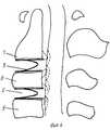
На фиг. 1 изображен общий вид конструкции; на фиг. 2 - вид сбоку; на фиг. 3 - вид конструкции после ее деформации в охлажденном состоянии; на фиг. 4 - схема применения конструкции. In FIG. 1 shows a general view of the structure; in FIG. 2 is a side view; in FIG. 3 - view of the structure after its deformation in a cooled state; in FIG. 4 is a design application diagram.
Конструкция выполнена из пластины сплава никелида титана ТЭН - 10, толщиной 1,8 мм с эффектом памяти формы. Конструкция выполнена в виде скобы, содержащей У-образную пластину 1, с боковыми плоскостями 2, угол 3 между боковыми плоскостями 2 составляет 30-36о симметрично расположенные ножки 4, отогнутые в противоположную сторону под углом 5, который составляет 15-20о к боковым плоскостям 2 пластины 1.The design is made of a plate of titanium nickelide alloy TEN - 10, 1.8 mm thick with shape memory effect. The design is made in the form of a bracket containing a
Используется конструкция следующим образом. The construction is used as follows.
Под общим обезболиванием в положении больного на спине осуществляется паратрахеальный доступ справа к передней поверхности тел шейных позвонков. Удаляется межпозвонковый диск (или несколько дисков по показаниям) и задние костные разрастания тел позвонков, сдавливающие спинной мозг. Конструкция охлаждается в течение 3-4 мин хлорэтилом до температуры -30оС и деформируется - сближаются между собой боковые плоскости 2 пластины 1 и ее ножки 4, при этом уменьшаются углы 3 и 5 соответственно до 10-12о и 5-7о. Конструкция в таком положении без труда помещается в полость удаленного межпозвонкового диска 6, таким образом, чтобы ножки 4 пластины 1 находились в задних отделах диска, а основание У-образной пластины 1 - в передних отделах диска (см. фиг. 4). Через 30 с в связи с контактным нагреванием никелида титана проявляется эффект памяти формы и конструкция стремится принять первоначально заданную форму. При этом концы боковых плоскостей 2 пластины 1 упираются в передние отделы замыкательных пластин смежных позвонков 7,8 и 8,9, а концы ножек 4 пластины 1 - в задние отделы, в связи с чем конструкция надежно фиксируется в межтеловом промежутке. Так как размеры пластины в вертикальной плоскости больше высоты межпозвонкового диска на 2-3 мм, то конструкция постоянно находится в напряженном состоянии, противодействия осевой нагрузке головы и позвоночника, что исключает перегрузку соседних сегментов. При этом сохранены наклонные движения в оперированном сегменте. При наклоне вперед уменьшается расстояние между плоскостями 2 пластины 1 и угол 3 между ними. При наклоне назад уменьшается расстояние между ножками 4 и угол 5. При наклоне позвоночника в сторону уменьшается расстояние между соответствующими отделами конструкции. Избыточные наклонные движения в сегменте будут ограничены увеличивающимся сопротивлением боковых плоскостей 2 и ножек 4 пластины 1. Рана послойно ушивается.Under general anesthesia in the patient’s position on the back, paratracheal access is made to the right of the anterior surface of the cervical vertebrae. The intervertebral disk (or several disks according to indications) and the posterior bone growths of the vertebral bodies, compressing the spinal cord, are removed. Structure cooled for 3-4 min chloroethyl to -30° C and deformed - converging between a
После операции не требуется внешняя иммобилизация позвоночника и больной без неврологического дефицита может приступить к труду через 1 месяц. Конструкция может быть использована на двух и более уровнях позвоночника. After the operation, external immobilization of the spine is not required and the patient without neurological deficit can begin work after 1 month. The design can be used at two or more levels of the spine.
Предлагаемая конструкция для замещения удаленного межпозвонкового диска у больных с дискогенной шейной миелопатией, оперированных чрездисковым способом обеспечивает надежную фиксацию смежных позвонков, сохраняет ограниченный объем движений в оперированном сегменте, предупреждает перегрузку соседних дисков, не нуждается во внешней иммобилизации позвоночника, в результате чего сокращаются сроки лечения больных и улучшаются исходы. The proposed design for replacing the remote intervertebral disk in patients with discogenic cervical myelopathy operated via the interdiscal method provides reliable fixation of adjacent vertebrae, maintains a limited range of movements in the operated segment, prevents overloading of adjacent disks, does not require external immobilization of the spine, resulting in reduced treatment time for patients and outcomes are improving.
Claims (2)
Translated fromRussianPriority Applications (1)
| Application Number | Priority Date | Filing Date | Title |
|---|---|---|---|
| SU5015113RU2020901C1 (en) | 1991-11-28 | 1991-11-28 | Intervertebral disc endoprosthesis |
Applications Claiming Priority (1)
| Application Number | Priority Date | Filing Date | Title |
|---|---|---|---|
| SU5015113RU2020901C1 (en) | 1991-11-28 | 1991-11-28 | Intervertebral disc endoprosthesis |
Publications (1)
| Publication Number | Publication Date |
|---|---|
| RU2020901C1true RU2020901C1 (en) | 1994-10-15 |
Family
ID=21590830
Family Applications (1)
| Application Number | Title | Priority Date | Filing Date |
|---|---|---|---|
| SU5015113RU2020901C1 (en) | 1991-11-28 | 1991-11-28 | Intervertebral disc endoprosthesis |
Country Status (1)
| Country | Link |
|---|---|
| RU (1) | RU2020901C1 (en) |
Cited By (16)
| Publication number | Priority date | Publication date | Assignee | Title |
|---|---|---|---|---|
| MD2901G2 (en)* | 2005-04-12 | 2006-07-31 | Филипп ГОРНЯ | Method of plasty of intervertebral disks of the cervical segment of the vertebral column |
| RU2281731C2 (en)* | 2004-04-06 | 2006-08-20 | Александр Кузьмич Чертков | Lumbar depertment's intervertebral implant |
| RU2282422C2 (en)* | 2002-03-12 | 2006-08-27 | Сервитек Инк. | Cervical intervertebral prosthesis |
| US7198047B2 (en) | 1999-08-18 | 2007-04-03 | Intrinsic Therapeutics, Inc. | Anchored anulus method |
| US7201775B2 (en) | 2002-09-24 | 2007-04-10 | Bogomir Gorensek | Stabilizing device for intervertebral disc, and methods thereof |
| US7500978B2 (en) | 2003-06-20 | 2009-03-10 | Intrinsic Therapeutics, Inc. | Method for delivering and positioning implants in the intervertebral disc environment |
| US7507243B2 (en) | 1999-08-18 | 2009-03-24 | Gregory Lambrecht | Devices and method for augmenting a vertebral disc |
| US7513911B2 (en) | 1999-08-18 | 2009-04-07 | Intrinsic Therapeutics, Inc. | Method of implanting dynamically stable spinal implant |
| US7553329B2 (en) | 1999-08-18 | 2009-06-30 | Intrinsic Therapeutics, Inc. | Stabilized intervertebral disc barrier |
| US7717961B2 (en) | 1999-08-18 | 2010-05-18 | Intrinsic Therapeutics, Inc. | Apparatus delivery in an intervertebral disc |
| US7727241B2 (en) | 2003-06-20 | 2010-06-01 | Intrinsic Therapeutics, Inc. | Device for delivering an implant through an annular defect in an intervertebral disc |
| US7959679B2 (en) | 1999-08-18 | 2011-06-14 | Intrinsic Therapeutics, Inc. | Intervertebral anulus and nucleus augmentation |
| US7972337B2 (en) | 2005-12-28 | 2011-07-05 | Intrinsic Therapeutics, Inc. | Devices and methods for bone anchoring |
| US8231678B2 (en) | 1999-08-18 | 2012-07-31 | Intrinsic Therapeutics, Inc. | Method of treating a herniated disc |
| US8323341B2 (en) | 2007-09-07 | 2012-12-04 | Intrinsic Therapeutics, Inc. | Impaction grafting for vertebral fusion |
| US8454612B2 (en) | 2007-09-07 | 2013-06-04 | Intrinsic Therapeutics, Inc. | Method for vertebral endplate reconstruction |
- 1991
- 1991-11-28RUSU5015113patent/RU2020901C1/enactive
Non-Patent Citations (1)
| Title |
|---|
| Патент ЕР N 0298235, A 61F 2/08, 1989.* |
Cited By (41)
| Publication number | Priority date | Publication date | Assignee | Title |
|---|---|---|---|---|
| US7998213B2 (en) | 1999-08-18 | 2011-08-16 | Intrinsic Therapeutics, Inc. | Intervertebral disc herniation repair |
| US8002836B2 (en) | 1999-08-18 | 2011-08-23 | Intrinsic Therapeutics, Inc. | Method for the treatment of the intervertebral disc anulus |
| US9706947B2 (en) | 1999-08-18 | 2017-07-18 | Intrinsic Therapeutics, Inc. | Method of performing an anchor implantation procedure within a disc |
| US7198047B2 (en) | 1999-08-18 | 2007-04-03 | Intrinsic Therapeutics, Inc. | Anchored anulus method |
| US9333087B2 (en) | 1999-08-18 | 2016-05-10 | Intrinsic Therapeutics, Inc. | Herniated disc repair |
| US8409284B2 (en) | 1999-08-18 | 2013-04-02 | Intrinsic Therapeutics, Inc. | Methods of repairing herniated segments in the disc |
| US7507243B2 (en) | 1999-08-18 | 2009-03-24 | Gregory Lambrecht | Devices and method for augmenting a vertebral disc |
| US7513911B2 (en) | 1999-08-18 | 2009-04-07 | Intrinsic Therapeutics, Inc. | Method of implanting dynamically stable spinal implant |
| US7524333B2 (en) | 1999-08-18 | 2009-04-28 | Intrinsic Therapeutics, Inc. | Method of anchoring an implant in an intervertebral disc |
| US7553330B2 (en) | 1999-08-18 | 2009-06-30 | Intrinsic Therapeutics, Inc. | Methods of reinforcing an intervertebral disc annulus |
| US7553329B2 (en) | 1999-08-18 | 2009-06-30 | Intrinsic Therapeutics, Inc. | Stabilized intervertebral disc barrier |
| US7563282B2 (en) | 1999-08-18 | 2009-07-21 | Intrinsic Therapeutics, Inc. | Method of supporting nucleus pulposus |
| US7658765B2 (en) | 1999-08-18 | 2010-02-09 | Intrinsic Therapeutics, Inc. | Resilient intervertebral disc implant |
| US7717961B2 (en) | 1999-08-18 | 2010-05-18 | Intrinsic Therapeutics, Inc. | Apparatus delivery in an intervertebral disc |
| US8257437B2 (en) | 1999-08-18 | 2012-09-04 | Intrinsic Therapeutics, Inc. | Methods of intervertebral disc augmentation |
| US7749275B2 (en) | 1999-08-18 | 2010-07-06 | Intrinsic Therapeutics, Inc. | Method of reducing spinal implant migration |
| US7867278B2 (en) | 1999-08-18 | 2011-01-11 | Intrinsic Therapeutics, Inc. | Intervertebral disc anulus implant |
| US7879097B2 (en) | 1999-08-18 | 2011-02-01 | Intrinsic Therapeutics, Inc. | Method of performing a procedure within a disc |
| US7959679B2 (en) | 1999-08-18 | 2011-06-14 | Intrinsic Therapeutics, Inc. | Intervertebral anulus and nucleus augmentation |
| US8231678B2 (en) | 1999-08-18 | 2012-07-31 | Intrinsic Therapeutics, Inc. | Method of treating a herniated disc |
| US8025698B2 (en) | 1999-08-18 | 2011-09-27 | Intrinsic Therapeutics, Inc. | Method of rehabilitating an anulus fibrosus |
| US8021425B2 (en) | 1999-08-18 | 2011-09-20 | Intrinsic Therapeutics, Inc. | Versatile method of repairing an intervertebral disc |
| RU2282422C2 (en)* | 2002-03-12 | 2006-08-27 | Сервитек Инк. | Cervical intervertebral prosthesis |
| US7201775B2 (en) | 2002-09-24 | 2007-04-10 | Bogomir Gorensek | Stabilizing device for intervertebral disc, and methods thereof |
| US7727241B2 (en) | 2003-06-20 | 2010-06-01 | Intrinsic Therapeutics, Inc. | Device for delivering an implant through an annular defect in an intervertebral disc |
| US7500978B2 (en) | 2003-06-20 | 2009-03-10 | Intrinsic Therapeutics, Inc. | Method for delivering and positioning implants in the intervertebral disc environment |
| RU2281731C2 (en)* | 2004-04-06 | 2006-08-20 | Александр Кузьмич Чертков | Lumbar depertment's intervertebral implant |
| MD2901G2 (en)* | 2005-04-12 | 2006-07-31 | Филипп ГОРНЯ | Method of plasty of intervertebral disks of the cervical segment of the vertebral column |
| US9610106B2 (en) | 2005-12-28 | 2017-04-04 | Intrinsic Therapeutics, Inc. | Bone anchor systems |
| US8394146B2 (en) | 2005-12-28 | 2013-03-12 | Intrinsic Therapeutics, Inc. | Vertebral anchoring methods |
| US11185354B2 (en) | 2005-12-28 | 2021-11-30 | Intrinsic Therapeutics, Inc. | Bone anchor delivery systems and methods |
| US10470804B2 (en) | 2005-12-28 | 2019-11-12 | Intrinsic Therapeutics, Inc. | Bone anchor delivery systems and methods |
| US9039741B2 (en) | 2005-12-28 | 2015-05-26 | Intrinsic Therapeutics, Inc. | Bone anchor systems |
| US7972337B2 (en) | 2005-12-28 | 2011-07-05 | Intrinsic Therapeutics, Inc. | Devices and methods for bone anchoring |
| US8114082B2 (en) | 2005-12-28 | 2012-02-14 | Intrinsic Therapeutics, Inc. | Anchoring system for disc repair |
| US8454612B2 (en) | 2007-09-07 | 2013-06-04 | Intrinsic Therapeutics, Inc. | Method for vertebral endplate reconstruction |
| US9226832B2 (en) | 2007-09-07 | 2016-01-05 | Intrinsic Therapeutics, Inc. | Interbody fusion material retention methods |
| US10076424B2 (en) | 2007-09-07 | 2018-09-18 | Intrinsic Therapeutics, Inc. | Impaction systems |
| US8361155B2 (en) | 2007-09-07 | 2013-01-29 | Intrinsic Therapeutics, Inc. | Soft tissue impaction methods |
| US10716685B2 (en) | 2007-09-07 | 2020-07-21 | Intrinsic Therapeutics, Inc. | Bone anchor delivery systems |
| US8323341B2 (en) | 2007-09-07 | 2012-12-04 | Intrinsic Therapeutics, Inc. | Impaction grafting for vertebral fusion |
Similar Documents
| Publication | Publication Date | Title |
|---|---|---|
| RU2020901C1 (en) | Intervertebral disc endoprosthesis | |
| US20220273459A1 (en) | Method and spacer device for spanning a space formed upon removal of an intervertebral disc | |
| US6846328B2 (en) | Articulating spinal implant | |
| Kawakami et al. | Axial symptoms and cervical alignments after cervical anterior spinal fusion for patients with cervical myelopathy | |
| US9925064B2 (en) | Intervertebral fusion implant | |
| US5607424A (en) | Domed cage | |
| US6159245A (en) | Box cage for intervertebral body fusion | |
| EP1290985B1 (en) | Intersomatic cage for posterior fusion surgery to the lumbar column | |
| US6132464A (en) | Vertebral joint facets prostheses | |
| CA1146301A (en) | Intervertebral disc prosthesis | |
| CA2611905C (en) | Anterior cervical plate | |
| EP2328495B1 (en) | Intervertebral fusion implant | |
| David | Lumbar disc prosthesis: surgical technique, indications and clinical results in 22 patients with a minimum of 12 months follow-up | |
| US20070050029A1 (en) | Method for correcting a deformity in the spinal column and its corresponding implant | |
| US20060178745A1 (en) | Intervertebral prosthetic disc | |
| US20050283237A1 (en) | Artificial spinal disk replacement device with staggered vertebral body attachments | |
| US20080039847A1 (en) | Implant and system for stabilization of the spine | |
| US20050261773A1 (en) | Lateral-approach artificial disc replacements | |
| US6682564B1 (en) | Intervertebral support device and related methods | |
| WO2001064142A1 (en) | Articulating spinal implant | |
| US12178710B2 (en) | Flexible interbody spacer and methods for use | |
| US20060129242A1 (en) | Pseudo arthrosis device | |
| Vaccaro et al. | Early findings in a pilot study of anterior cervical fusion in which bioabsorbable interbody spacers were used | |
| RU2014041C1 (en) | Prosthesis for vertebra body | |
| US20150289986A1 (en) | Flanged endplate for an intervertebral disc prosthesis and intervertebral disc prosthesis incorporating same |