RU198216U1 - Flip and cabinet - Google Patents
Flip and cabinetDownload PDFInfo
- Publication number
- RU198216U1 RU198216U1RU2020100204URU2020100204URU198216U1RU 198216 U1RU198216 U1RU 198216U1RU 2020100204 URU2020100204 URU 2020100204URU 2020100204 URU2020100204 URU 2020100204URU 198216 U1RU198216 U1RU 198216U1
- Authority
- RU
- Russia
- Prior art keywords
- gripping
- component
- overturning device
- flipping
- item
- Prior art date
Links
- 230000007246mechanismEffects0.000claimsabstractdescription121
- 230000007306turnoverEffects0.000abstract1
- 238000001514detection methodMethods0.000description9
- 238000000034methodMethods0.000description3
- 238000005096rolling processMethods0.000description3
- 238000005516engineering processMethods0.000description2
- 230000008569processEffects0.000description2
- 230000004075alterationEffects0.000description1
- 230000005540biological transmissionEffects0.000description1
- 230000003993interactionEffects0.000description1
Images


Classifications
- A—HUMAN NECESSITIES
- A47—FURNITURE; DOMESTIC ARTICLES OR APPLIANCES; COFFEE MILLS; SPICE MILLS; SUCTION CLEANERS IN GENERAL
- A47B—TABLES; DESKS; OFFICE FURNITURE; CABINETS; DRAWERS; GENERAL DETAILS OF FURNITURE
- A47B49/00—Revolving cabinets or racks; Cabinets or racks with revolving parts
- A47B49/004—Cabinets with compartments provided with trays revolving on a vertical axis
- G—PHYSICS
- G07—CHECKING-DEVICES
- G07F—COIN-FREED OR LIKE APPARATUS
- G07F11/00—Coin-freed apparatus for dispensing, or the like, discrete articles
- G07F11/02—Coin-freed apparatus for dispensing, or the like, discrete articles from non-movable magazines
- G07F11/38—Coin-freed apparatus for dispensing, or the like, discrete articles from non-movable magazines in which the magazines are horizontal
- G07F11/42—Coin-freed apparatus for dispensing, or the like, discrete articles from non-movable magazines in which the magazines are horizontal the articles being delivered by motor-driven means
- A—HUMAN NECESSITIES
- A47—FURNITURE; DOMESTIC ARTICLES OR APPLIANCES; COFFEE MILLS; SPICE MILLS; SUCTION CLEANERS IN GENERAL
- A47B—TABLES; DESKS; OFFICE FURNITURE; CABINETS; DRAWERS; GENERAL DETAILS OF FURNITURE
- A47B49/00—Revolving cabinets or racks; Cabinets or racks with revolving parts
- A—HUMAN NECESSITIES
- A47—FURNITURE; DOMESTIC ARTICLES OR APPLIANCES; COFFEE MILLS; SPICE MILLS; SUCTION CLEANERS IN GENERAL
- A47B—TABLES; DESKS; OFFICE FURNITURE; CABINETS; DRAWERS; GENERAL DETAILS OF FURNITURE
- A47B49/00—Revolving cabinets or racks; Cabinets or racks with revolving parts
- A47B49/008—Revolving cabinets or racks; Cabinets or racks with revolving parts with motorisation means
- A—HUMAN NECESSITIES
- A47—FURNITURE; DOMESTIC ARTICLES OR APPLIANCES; COFFEE MILLS; SPICE MILLS; SUCTION CLEANERS IN GENERAL
- A47B—TABLES; DESKS; OFFICE FURNITURE; CABINETS; DRAWERS; GENERAL DETAILS OF FURNITURE
- A47B97/00—Furniture or accessories for furniture, not provided for in other groups of this subclass
- G—PHYSICS
- G07—CHECKING-DEVICES
- G07F—COIN-FREED OR LIKE APPARATUS
- G07F11/00—Coin-freed apparatus for dispensing, or the like, discrete articles
- G07F11/02—Coin-freed apparatus for dispensing, or the like, discrete articles from non-movable magazines
- G07F11/04—Coin-freed apparatus for dispensing, or the like, discrete articles from non-movable magazines in which magazines the articles are stored one vertically above the other
- G07F11/16—Delivery means
- G07F11/165—Delivery means using xyz-picker or multi-dimensional article picking arrangements
- G07F11/1657—Delivery means using xyz-picker or multi-dimensional article picking arrangements the picking arrangements using suction
- G—PHYSICS
- G07—CHECKING-DEVICES
- G07F—COIN-FREED OR LIKE APPARATUS
- G07F17/00—Coin-freed apparatus for hiring articles; Coin-freed facilities or services
- G07F17/10—Coin-freed apparatus for hiring articles; Coin-freed facilities or services for means for safe-keeping of property, left temporarily, e.g. by fastening the property
- G07F17/12—Coin-freed apparatus for hiring articles; Coin-freed facilities or services for means for safe-keeping of property, left temporarily, e.g. by fastening the property comprising lockable containers, e.g. for accepting clothes to be cleaned
- B—PERFORMING OPERATIONS; TRANSPORTING
- B65—CONVEYING; PACKING; STORING; HANDLING THIN OR FILAMENTARY MATERIAL
- B65G—TRANSPORT OR STORAGE DEVICES, e.g. CONVEYORS FOR LOADING OR TIPPING, SHOP CONVEYOR SYSTEMS OR PNEUMATIC TUBE CONVEYORS
- B65G47/00—Article or material-handling devices associated with conveyors; Methods employing such devices
- B65G47/74—Feeding, transfer, or discharging devices of particular kinds or types
- B65G47/90—Devices for picking-up and depositing articles or materials
Landscapes
- Physics & Mathematics (AREA)
- General Physics & Mathematics (AREA)
- Specific Conveyance Elements (AREA)
- Warehouses Or Storage Devices (AREA)
- Handcart (AREA)
- De-Stacking Of Articles (AREA)
Abstract
Translated fromRussianDescription
Translated fromRussianПриоритет настоящей заявки испрашивается по заявке на патент Китая №201820687067.0, которая озаглавлена «Шкаф для хранения и переворачивающее устройство» и подана 9 мая 2018 года и содержание которой полностью включено в настоящую заявку посредством ссылки.The priority of this application is claimed for China Patent Application No. 201820687067.0, which is entitled “Storage Cabinet and Tumbler” and filed May 9, 2018 and the contents of which are fully incorporated into this application by reference.
ОБЛАСТЬ ПРИМЕНЕНИЯAPPLICATION AREA
Настоящая заявка относится к технологии хранения в шкафах, например, к переворачивающему устройству и к шкафу для хранения.The present application relates to storage technology in cabinets, for example, a rolling device and a storage cabinet.
ПРЕДПОСЫЛКИ ПОЛЕЗНОЙ МОДЕЛИBACKGROUND OF USEFUL MODEL
При значительном усовершенствовании высоких новых технических решений качество жизни населения в недавние годы улучшилось, и жизнь людей становится удобной. В реальной жизни широко используются интеллектуальные шкафы для хранения. В интеллектуальных шкафах для хранения предметы непосредственно хранятся в различных отделениях шкафов, и занимаемое ими пространство можно сэкономить.With significant improvements in high new technical solutions, the quality of life has improved in recent years, and people's lives are becoming more comfortable. In real life, smart storage cabinets are widely used. In smart storage cabinets, items are directly stored in various compartments of cabinets, and the space they occupy can be saved.
Однако, высота многогранных шкафов для хранения (например, восьмиугольных шкафов), полок для хранения предметов и полок для хранения в один слой является фиксированной в существующих шкафах, и организационное устройство шкафа рассчитывает количество слоев полок, которые будут заняты предметом, в соответствии с определенной высотой предмета, который нужно положить на полку, так, чтобы выбрать оптимальное место хранения, и затем поддон, содержащий этот предмет, помещается в назначенное положение путем выполнения растяжения, поворота и перемещения передающего механизма.However, the height of multifaceted storage cabinets (for example, octagonal cabinets), shelves for storing items and storage shelves in one layer is fixed in existing cabinets, and the organizational device of the cabinet calculates the number of layers of shelves that will be occupied by the item, according to a certain height an object to be put on a shelf so as to select an optimal storage location, and then the pallet containing this object is placed in the designated position by stretching, turning and moving the transmission mechanism.
Но, когда люди кладут предмет на хранение, они часто укладывают предмет на поддон в загрузочном отверстии случайным образом, что может вызвать неправильное расположение этого предмета. Когда предмет находится в неправильном положении в том, что касается высоты или расположения, расположение предмета на поддоне не в центре может привести к тому, что предмет может легко упасть или он может выпасть во время процессов перемещения, поворота и подъема. Кроме того, предмет, находящийся на полке, занимает пространство, высота которого превышает реально требуемую высоту, и больше слоев в шкафу оказываются занятыми, что приводит к неиспользованию пространства для хранения.But, when people put the item in storage, they often put the item on a pallet in the loading hole at random, which can cause the item to be misplaced. When an item is in the wrong position with regard to height or location, not placing the item on the pallet in the center can cause the item to fall easily or fall out during the movement, rotation, and lifting processes. In addition, an object located on a shelf occupies a space whose height exceeds the actually required height, and more layers in the cabinet are occupied, which leads to non-use of storage space.
СУЩНОСТЬ ПОЛЕЗНОЙ МОДЕЛИESSENCE OF A USEFUL MODEL
Представленная заявка предлагает переворачивающее устройство и шкаф для хранения, так что неправильно расположенный предмет может быть перевернут с помощью переворачивающего устройства и затем помещен в надлежащее положение на поддоне, вследствие чего предмет оказывается защищенным, а степень использования пространства для хранения в шкафу увеличивается.The submitted application proposes an overturning device and a storage cabinet, so that an improperly positioned object can be inverted using an overturning device and then placed in an appropriate position on the pallet, as a result of which the object is protected and the degree of utilization of the storage space in the cabinet increases.
В одном варианте выполнения предложено переворачивающее устройство шкафа для хранения. Переворачивающее устройство расположено в шкафу для хранения и содержит корпус, который имеет опорную раму, поворотный механизм, выполненный с обеспечением возможности поворота переворачивающего устройства, захватный механизм, выполненный с возможностью захвата предмета, переворачивающий механизм, выполненный с обеспечением возможности переворота предмета захватным механизмом, и подъемный механизм, выполненный с обеспечением возможности перемещения захватного механизма вверх и вниз, причем поворотный механизм, захватный механизм, переворачивающий механизм и подъемный механизм расположены на опорной раме.In one embodiment, a flipping device of a storage cabinet is provided. The overturning device is located in the storage cabinet and includes a housing that has a support frame, a rotary mechanism configured to rotate the overturning device, a gripping mechanism configured to capture an item, a flipping mechanism configured to allow the object to be turned over by a gripping mechanism, and a lifting mechanism a mechanism configured to allow the gripping mechanism to be moved up and down, the pivoting mechanism, the gripping mechanism, the flipping mechanism, and the lifting mechanism are located on the support frame.
В одном варианте выполнения предложен шкаф для хранения. Шкаф для хранения содержит корпус, механизм обнаружения, управляющий механизм и переворачивающее устройство, описанное выше, причем корпус шкафа содержит поддон, расположенный в корпусе шкафа, механизм обнаружения расположен в корпусе шкафа и выполнен с возможностью определения размера предмета и положения предмета на поддоне, а управляющий механизм выполнен с возможностью контроля рабочих состояний механизма обнаружения и переворачивающего устройства для управления этим устройством для укладывания предмета в назначенное положение на поддоне в соответствии с результатами определения, полученными механизмом обнаружения.In one embodiment, a storage cabinet is provided. The storage cabinet comprises a housing, a detection mechanism, a control mechanism and a flip device described above, wherein the cabinet body includes a pallet located in the cabinet body, the detection mechanism is located in the cabinet body and is configured to determine the size of the item and the position of the item on the pallet, and the control the mechanism is configured to control the operating states of the detection mechanism and the flipping device to control this device for laying the item in the designated position on the pallet in accordance with the determination results obtained by the detection mechanism.
КРАТКОЕ ОПИСАНИЕ ЧЕРТЕЖЕЙBRIEF DESCRIPTION OF THE DRAWINGS
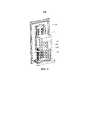
Фиг. 1 схематически изображает переворачивающее устройство в соответствии с одним вариантом выполнения;FIG. 1 schematically depicts a rolling device in accordance with one embodiment;
Фиг. 2 схематически изображает переворачивающее устройство, расположенное у входного отверстия в шкафу для хранения в соответствии с одним вариантом выполнения;FIG. 2 schematically depicts a flipping device located at an inlet in a storage cabinet in accordance with one embodiment;
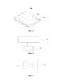
Фиг. 3а схематически иллюстрирует положение 1 при изменении ориентации неправильно расположенного предмета с помощью переворачивающего устройства в соответствии с одним вариантом выполнения;FIG. 3a schematically illustrates position 1 when changing the orientation of an improperly positioned object using a flip device in accordance with one embodiment;
Фиг. 3b схематически иллюстрирует положение 2 при изменении ориентации неправильно расположенного предмета с помощью переворачивающего устройства в соответствии с одним вариантом выполнения;FIG. 3b schematically illustrates position 2 when changing the orientation of an improperly positioned object using a flip device in accordance with one embodiment;
Фиг. 3с схематически иллюстрирует положение 3 при изменении ориентации неправильно расположенного предмета с помощью переворачивающего устройства в соответствии с одним вариантом выполнения;FIG. 3c schematically illustrates
Фиг 3d схематически иллюстрирует положение 4 при изменении ориентации неправильно расположенного предмета с помощью переворачивающего устройства в соответствии с одним вариантом выполнения;FIG. 3d schematically illustrates
Фиг. 4 схематически иллюстрирует положение предмета, размещенного на поддоне с помощью переворачивающего устройства в соответствии с одним вариантом выполнения;FIG. 4 schematically illustrates the position of an item placed on a pallet using a flip device in accordance with one embodiment;
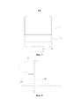
Фиг. 5 схематически изображает соединение первого приводного компонента переворачивающего устройства с поворотным столом в соответствии с одним вариантом выполнения;FIG. 5 schematically depicts a connection of a first drive component of a rolling device with a turntable in accordance with one embodiment;
Фиг. 6 схематически изображает соединение второго приводного компонента переворачивающего устройства с присасывающим диском переворачивающего устройства в соответствии с одним вариантом выполнения;FIG. 6 schematically depicts a connection of a second drive component of a flip device with a suction disk of a flip device in accordance with one embodiment;
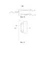
Фиг. 7 схематически изображает соединение третьего приводного компонента переворачивающего устройства с соединительным элементом переворачивающего устройства в соответствии с одним вариантом выполнения;FIG. 7 schematically depicts a connection of a third drive component of a flip device with a connecting element of a flip device in accordance with one embodiment;
Фиг. 8 схематически изображает соединение четвертого приводного компонента переворачивающего устройства с ползуном переворачивающего устройства в соответствии с одним вариантом выполнения;FIG. 8 schematically depicts a connection of a fourth drive component of a flip device with a slider of a flip device in accordance with one embodiment;
Фиг. 9 схематически изображает конструкцию переворачивающего устройства, расположенного на телескопическом перемещающем механизме в шкафу для хранения в соответствии с одним вариантом выполнения;FIG. 9 schematically depicts a design of a flipping device located on a telescopic moving mechanism in a storage cabinet in accordance with one embodiment;
Фиг. 10 схематически иллюстрирует соединение управляющего механизма шкафа для хранения в соответствии с одним вариантом выполнения;FIG. 10 schematically illustrates a connection of a control mechanism of a storage cabinet in accordance with one embodiment;
Фиг. 11 схематически изображает присоединение корпуса переворачивающего устройства шкафа для хранения к поднимающему механизму в соответствии с одним вариантом выполнения.FIG. 11 schematically depicts the attachment of a cabinet of a cabinet of a storage cabinet to a lifting mechanism in accordance with one embodiment.
ПОДРОБНОЕ ОПИСАНИЕDETAILED DESCRIPTION
В вариантах выполнения термины, относящиеся к ориентации, такие как «влево», «вправо», «выше» и «ниже», являются только относительными понятиями или ссылками на состояние изделия при обычном использовании, и их не следует рассматривать как ограничения.In embodiments, terms related to orientation, such as “left,” “right,” “above,” and “below,” are only relative terms or references to the state of the product during normal use, and should not be construed as limitations.
Как показано на Фиг. 1 и 2, в соответствии с одним вариантом выполнения предложено переворачивающее устройство, которое расположено в шкафу 200 для хранения и содержит корпус 100, причем корпус 100 переворачивающего устройства содержит опорную раму 1, поворотный механизм (не изображен), выполненный с обеспечением возможности поворота корпуса 100 переворачивающего устройства, захватный механизм 3, выполненный с возможностью захвата предмета 300, переворачивающий механизм (не изображен), выполненный с обеспечением возможности переворота предмета 300 захватным механизмом 3, и подъемный механизм (не изображен), выполненный с обеспечением возможности перемещения захватного механизма вверх и вниз; причем поворотный механизм, захватный механизм 3, переворачивающий механизм и подъемный механизм расположены на опорной раме 1. С помощью корпуса 100 предмет 300 можно переворачивать и перемещать во множестве направлений, так что предмет 300 оказывается повернутым в оптимальное положение и помещен на поддон. С одной стороны, это обеспечивает, что предмет 300 не будет легко сброшен или не выпадет во время процесса перемещения поворотом и при подъеме; с другой стороны, высота пространства шкафа для хранения будет использоваться максимально, и степень использования пространства для хранения шкафа будет увеличена.As shown in FIG. 1 and 2, in accordance with one embodiment, a flip device is provided, which is located in a
В одном варианте выполнения, показанном на Фиг. 1 и 5, поворотный механизм содержит поворотный стол 21, выполненный с возможностью поворота корпуса 100 переворачивающего устройства, и первый приводной компонент 22, выполненный с обеспечением возможности поворота поворотного стола 21 и присоединенный к поворотному столу 21, расположенному на опорной раме 1, причем поворотный стол 21 поворачивается первым приводным компонентом 22, а затем захватный механизм 3, переворачивающий механизм и подъемный механизм поворачиваются поворотным столом 21, то есть, весь корпус 100 переворачивающего устройства поворачивается. В одном варианте выполнения поворотный механизм заставляет поворачиваться весь корпус 100 устройства в вертикальном направлении (вокруг направления оси Z).In one embodiment shown in FIG. 1 and 5, the pivoting mechanism comprises a pivot table 21 configured to pivot the
Снова обращаясь к Фиг. 1 и 2, захватный механизм 3 содержит захватный компонент 31, выполненный с возможностью захвата предмета 300, и перемещающий компонент 32, выполненный с возможностью управления захватным компонентом 31 для его размыкания и смыкания в соответствии с размером предмета 300, причем перемещающий компонент 32 расположен на поворотном столе 21 с помощью установочного элемента 6, подъемный механизм расположен на перемещающем компоненте 32, и захватный компонент 31 расположен на подъемном механизме. Подъемный механизм приводит в движение захватный компонент 31 для опускания на середину предмета в направлении его высоты, так что захватный компонент 31 располагается с двух сторон предмета и затем смыкается для захвата предмета 300 с помощью перемещающего компонента 32, после чего подъемный механизм поднимает захватный компонент 31 и предмет на некоторую высоту, затем перемещающий компонент 32 перемещает предмет 300 в оптимальное положение и, совместно с подъемным механизмом, захватный компонент 31 и предмет 300 опускаются, чтобы опустить на место предмет 300 в оптимальное положение на поддоне, и наконец, перемещающий компонент 3 дает возможность захватному компоненту 31 выпустить предмет 300, и затем предмет 300 размещается на поддоне.Referring again to FIG. 1 and 2, the
В одном варианте выполнения захватный компонент 31 содержит два присасывающих диска 311 и соединительный элемент 312, выполненный с возможностью установки присасывающих дисков 311, причем диски 311 расположены на соединительном элементе 312, который расположен на подъемном механизме, при этом два диска 311 могут зажать предмет 300, прикрепляясь к нему, так что предмет 300, кроме того, защищен от повреждения. Соединительный элемент 312 присоединен подобно втулке к направляющей колонне 51, так что диски 311 могут скользить вверх и вниз по направляющей колонне.In one embodiment, the
Как показано на Фиг. 1 и 7, подъемный механизм содержит две группы направляющих колонн 51 и третий приводной компонент 52, выполненный с обеспечением возможности перемещения дисков 311 вверх и вниз вдоль направляющих колонн 51, причем соединительный элемент 312 присоединен подобно втулке к направляющим колоннам 51, третий приводной компонент 52 приводит в движение соединительный элемент 312 для перемещения вверх и вниз вдоль направляющих колонн 51, при этом соединительный элемент 312 приводится в движение вверх вдоль направляющих колонн 51 с помощью третьего приводного компонента 52, так что предмет 300, захваченный дисками 311, поднимается вверх на требуемую высоту для его переворачивания, затем предмет 300, с помощью переворачивающего механизма, переворачивается горизонтально (вдоль оси X или оси Y), затем, после того, как предмет 300 опускается на поддон на отрегулированной высоте, захватный механизм 3 отсоединяется.As shown in FIG. 1 and 7, the lifting mechanism comprises two groups of
Как изображено на Фиг. 1 и 8, перемещающий компонент 32 содержит опорный стержень 321, выполненный с возможностью присоединения к поворотному столу 21, ползун 322, выполненный с обеспечением возможности перемещения направляющих колонн 51 для регулирования расстояния между двумя присасывающими дисками 311, и четвертый приводной компонент 323, приводящий в движение ползун 322, чтобы он скользил на опорном стержне 321. В одном варианте выполнения опорный стержень 321 расположен в нижней части поворотного стола 21 с помощью установочного элемента 6, ползун 322 расположен на опорном стержне 321, направляющие колонны 51 размещены на ползуне 322, четвертый приводной компонент 323 приводит в движение ползун 322 для того, чтобы он скользил на опорном стержне 321, и вследствие взаимодействия между ползуном 322 и опорным стержнем 321 диски 311 могут захватывать предмет 300 и перемещать его в оптимальное положение. В одном варианте выполнения на каждом из двух концов опорного стержня 321 расположен стопор 323 для предотвращения соскальзывания ползуна 322 с опорного стержня 321.As shown in FIG. 1 and 8, the moving
В одном варианте выполнения переворачивающий механизм связан с захватным механизмом 3, как изображено на Фиг. 6, причем переворачивающий механизм содержит второй приводной компонент 4, выполненный с обеспечением возможности поворота дисков 311 для переворачивания предмета 300, и диски 311 установлены на соединительном элементе 312 с возможностью поворота. После того, как диски 311 захватят предмет 300, подъемный механизм поднимает его на требуемую высоту для переворачивания предмета 300 в соответствии с его размером, затем диски 311 поворачиваются вторым приводным компонентом, так что переворачивание предмета 300 вдоль линии соединения между двумя дисками 311 завершается, и предмет 300 переворачивается, располагаясь, занимая оптимальную высоту.In one embodiment, the flipping mechanism is coupled to the
Переворачивающее устройство шкафа для хранения дополнительно содержит передвигающий механизм 400, который выполнен с обеспечением возможности перемещения корпуса 100 переворачивающего устройства, как изображено на Фиг. 11, при этом опорная рама 1 расположена на передвигающем механизме 400; при взаимодействии между передвигающим механизмом 400 и поворотным механизмом предмет 300, зажатый дисками 311, может перемещаться и поворачиваться во множестве направлений, так что предмет 300 оказывается в оптимальном положении для сбережения занимаемого пространства с наибольшим результатом.The overturning device of the storage cabinet further comprises a
Корпус 100 переворачивающего устройства выполнен с возможностью разместить предмет 300 в соответствии с потребностями пользователя, причем способ поворота и перемещения предмета 300 подробно описан ниже со ссылкой на Фиг. 3 и 4.The
Когда предмет 300 находится в положении, изображенном на Фиг. 3а, захватный механизм 3 зажимает его, затем подъемный механизм поднимает предмет 300 на требуемую высоту для переворачивания, затем переворачивающий механизм переворачивает предмет 300 вдоль оси X в направлении переворачивания, показанном стрелкой на Фиг. 3а, наконец предмет 300 опускают на поддон 201 с помощью подъемного механизма и захватного механизма 3, и диски 311 отпускают предмет 300, так что он может быть размещен в оптимальном положении, показанном на Фиг. 3.When the
Когда предмет находится в положении, показанном на Фиг. 3b, после того, как диски 311 зажали предмет и подняли его на некоторую высоту, предмет 300 переворачивают вдоль оси X с помощью переворачивающего механизма, объединенного с захватным механизмом 3, то есть, диски 311 поворачиваются в направлении, показанном стрелкой на Фиг. 3b, и тогда переворачивающее устройство перемещается на определенное расстояние вокруг оси X, так что предмет может быть помещен в оптимальном положении.When the item is in the position shown in FIG. 3b, after the
Когда предмет находится в положении, показанном на Фиг. 3с, после того, как диски 311 зажали предмет и подняли его на некоторую высоту, поворотный стол 21 поворачивается, так чтобы повернуть корпус 100 переворачивающего устройства на 90 градусов вдоль направления оси Z, то есть чтобы повернуть корпус 100 переворачивающего устройства на 90 градусов в направлении, показанном стрелкой на Фиг. 3с, и затем предмет 300 переворачивают вокруг оси Y с помощью переворачивающего механизма, объединенного с захватным механизмом 3, так что предмет 300 может быть размещен в оптимальном положении.When the item is in the position shown in FIG. 3c, after the
Когда предмет находится в положении, изображенном на Фиг. 3d, после того, как диски 311 зажали предмет и подняли его на определенную высоту, корпус 100 переворачивающего устройства может поворачиваться на 90 градусов вокруг оси Z с помощью поворотного стола 21, то есть корпус 100 переворачивающего устройства переворачивается на 90 градусов в направлении, которое указано стрелкой, изображенной на Фиг. 3d, и затем предмет 300 переворачивают вокруг оси X с помощью переворачивающего механизма, объединенного с захватным механизмом 3, так что предмет 300 может быть размещен в оптимальном положении.When the item is in the position shown in FIG. 3d, after the
Следовательно, предмет 300 независимо от того, где пользователь его разместит, может быть размещен в оптимальном положении, которое проиллюстрировано на Фиг. 4, с помощью переворачивающего устройства, которое подходит для телескопического перемещающего устройства в шкафу 200 для хранения для приема и установки на место поддона, и когда переворачивающее и подъемное устройство поворачивается и перемещается, предмет не выпадет наружу или не упадет, и пространство для хранения в шкафу может дополнительно быть должным образом использовано для увеличения степени его использования.Therefore, the
Как показано на фиг.2, 9 и 10, с учетом описанного выше переворачивающего устройства шкафа 200 для хранения, в этом варианте выполнения соответственно предложен шкаф 200 для хранения, который содержит корпус и поддон 201, расположенный в корпусе шкафа, причем корпус шкафа дополнительно снабжен механизмом 20 обнаружения, переворачивающим устройством и управляющим механизмом 10, причем механизм 20 обнаружения выполнен с возможностью определения размера предмета 300 и его положения на поддоне 201, причем управляющий механизм 10 выполнен с возможностью контроля состояния механизма 20 обнаружения и переворачивающего устройства 100, и управляющий механизм 10 управляет корпусом 100 переворачивающего устройства для размещения предмета 300 в требуемом положении на поддоне 201 в соответствии с параметрами, определенными механизмом 20 обнаружения.As shown in FIGS. 2, 9 and 10, taking into account the above-described inverting device of the
В одном варианте выполнения шкаф для хранения дополнительно имеет загрузочное отверстие 202 и телескопический перемещающий механизм 203, причем переворачивающее устройство расположено у загрузочного отверстия 202 или телескопического механизма 203. В одном из вариантов выполнения переворачивающее устройство расположено в верхней части загрузочного отверстия 202 или телескопического механизма 203, при этом переворачивающее устройство может быть расположено в другом месте шкафа для хранения, если только это не повредит нормальному использованию шкафа.In one embodiment, the storage cabinet further has a
В примере, в котором переворачивающее устройство расположено у загрузочного отверстия 202, когда пользователь помещает предмет 300 на поддон 201, механизм обнаружения определяет размер, расположение, ориентацию и подобные параметры предмета 300, при этом управляющий механизм 10 определяет, требуется ли какая-либо регулировка. Если регулировка необходима, управляющий механизм 10 рассчитывает, в каком направлении нужно выполнить регулировку для достижения оптимального положения, и посылает управляющий сигнал переворачивающему устройству для управления этим устройством для завершения регулировки ориентации предмета 300. После того, как предмет 300 окажется в оптимальном положении на поддоне, телескопический перемещающий механизм 203 шкафа для хранения захватывает поддон и затем поворачивающее и подъемное устройство поворачивает поддон на полку с помощью поднимающей пары для того, чтобы установить поддон на полку. В соответствии с этим вариантом выполнения, предмет 300 переворачивают в трех измерениях, так что предмет 300 оказывается размещенным, занимая наиболее правильную высоту; с одной стороны, гарантируется, что предмет 300 не сможет легко выпасть или упасть во время поворачивания и подъема в процессе транспортировки; с другой стороны, максимизировано использование высоты пространства шкафа для хранения и улучшена степень использования пространства для хранения.In the example in which the flip device is located at the
В одном варианте выполнения шкаф 200 для хранения является шкафом для выдачи товара, шкафом для хранения предметов или шкафом для обмена книг, так что шкаф 200 в этом варианте выполнения может использоваться, например, для выдачи товаров, для хранения, отправления и получения товаров, предназначенных для выдачи, и дополнительно может использоваться для временного хранения предметов в торговых заведениях, получения книги из библиотеки и тому подобного.In one embodiment, the
В представленном варианте выполнения переворачивающее устройство расположено в шкафу для хранения, причем корпус переворачивающего устройства содержит опорную раму 1, поворотный механизм, выполненный с обеспечением возможности поворота корпуса переворачивающего устройства, захватный механизм, выполненный с возможностью захвата предмета, переворачивающий механизм, выполненный с обеспечением возможности переворота предмета захватным механизмом, и подъемный механизм, выполненный с возможностью управления захватным механизмом для перемещения вверх и вниз, причем поворотный механизм, захватный механизм, переворачивающий механизм и подъемный механизм размещены на опорной раме 1, и с помощью поворотного механизма, захватного механизма, переворачивающего механизма и подъемного механизма реальный предмет может быть перевернут и перемещен во многих направлениях, так что предмет оказывается помещенным в наиболее правильное положение; с одной стороны, гарантированно, что предмет не выпадет наружу или не упадет при повороте и подъеме в процессе перемещения; с другой стороны, максимизировано использование высоты пространства шкафа для хранения и улучшена степень использования пространства для хранения.In the present embodiment, the flipping device is located in a storage cabinet, the flipping device housing comprising a support frame 1, a pivoting mechanism configured to rotate the flipping device body, a gripping mechanism configured to grip an object, flipping mechanism configured to allow flipping object gripping mechanism, and a lifting mechanism configured to control the gripping mechanism to move up and down, and the rotary mechanism, the gripping mechanism, the flipping mechanism and the lifting mechanism are placed on the support frame 1, and using the rotary mechanism, the gripping mechanism, the turning mechanism and lifting mechanism, a real object can be turned over and moved in many directions, so that the object is placed in the most correct position; on the one hand, it is guaranteed that the object will not fall out or fall when turning and lifting during the movement; on the other hand, the utilization of the height of the storage space of the cabinet has been maximized and the utilization of the storage space has been improved.
Переворачивающее устройство, предоставленное в этом варианте выполнения, имеет простую конструкцию при низкой стоимости, при этом переделку шкафа для хранения можно выполнить по соответствующим технологиям без повреждения основного корпуса существующего шкафа для хранения, и оно может быть широко распространено.The overturn device provided in this embodiment has a simple design at a low cost, while the alteration of the storage cabinet can be performed by appropriate technologies without damaging the main body of the existing storage cabinet, and it can be widely distributed.
Кроме этого, шкаф для хранения в соответствии с этим вариантом выполнения может использоваться, например, для выдачи товаров, для хранения, отправления и получения товаров, предназначенных для выдачи, и дополнительно может использоваться для временного хранения предметов в торговых заведениях, и может использоваться для различных целей.In addition, the storage cabinet in accordance with this embodiment can be used, for example, for dispensing goods, for storing, sending and receiving goods intended for dispensing, and can additionally be used for temporary storage of items in trade establishments, and can be used for various goals.
Claims (13)
Translated fromRussianApplications Claiming Priority (3)
| Application Number | Priority Date | Filing Date | Title |
|---|---|---|---|
| CN201820687067.0 | 2018-05-09 | ||
| CN201820687067.0UCN208891890U (en) | 2018-05-09 | 2018-05-09 | A kind of locker and its turnover device |
| PCT/CN2018/113022WO2019214176A1 (en) | 2018-05-09 | 2018-10-31 | Flipping apparatus and locker |
Publications (1)
| Publication Number | Publication Date |
|---|---|
| RU198216U1true RU198216U1 (en) | 2020-06-23 |
Family
ID=66565879
Family Applications (1)
| Application Number | Title | Priority Date | Filing Date |
|---|---|---|---|
| RU2020100204URU198216U1 (en) | 2018-05-09 | 2018-10-31 | Flip and cabinet |
Country Status (6)
| Country | Link |
|---|---|
| EP (1) | EP3622855B1 (en) |
| KR (1) | KR200494268Y1 (en) |
| CN (1) | CN208891890U (en) |
| CO (1) | CO2019014826A2 (en) |
| RU (1) | RU198216U1 (en) |
| WO (1) | WO2019214176A1 (en) |
Families Citing this family (12)
| Publication number | Priority date | Publication date | Assignee | Title |
|---|---|---|---|---|
| CN110465922A (en)* | 2019-08-02 | 2019-11-19 | 合肥嘉东光学股份有限公司 | A kind of plated film parts convenient for substrate automatic turning |
| CN112444034A (en)* | 2019-09-03 | 2021-03-05 | 东莞御膳坊信息技术有限公司 | Intelligent refrigerator and control method thereof |
| CN112265809B (en)* | 2020-09-22 | 2025-03-14 | 深圳云宣存储科技有限公司 | External clamping disc flipping and placing mechanism |
| CN112960390A (en)* | 2021-04-06 | 2021-06-15 | 太原科技大学 | Three-axis moving clamping device suitable for small and medium-sized goods |
| CN112959349A (en)* | 2021-04-26 | 2021-06-15 | 林秀纯 | Multi-section steering manipulator |
| CN114474854B (en)* | 2022-01-22 | 2023-09-19 | 四川大胜达中飞包装科技有限公司 | Pneumatic box pressing machine |
| CN115123812B (en)* | 2022-07-09 | 2024-03-01 | 福鼎市艺双自动化设备制造有限公司 | Automatic conveying and processing device for front and back surfaces of workpiece and control method thereof |
| CN115256440B (en)* | 2022-08-30 | 2025-03-21 | 山东东都汽车部件股份有限公司 | End picker and end picker suction cup for industrial robot |
| CN115476334B (en)* | 2022-10-13 | 2024-11-15 | 广州大学 | A library automatic book retrieval and return robot |
| CN116276932B (en)* | 2023-05-22 | 2023-08-11 | 哈尔滨商业大学 | A turning robot |
| CN116810832A (en)* | 2023-07-20 | 2023-09-29 | 上海诺加克机电装备有限公司 | Heavy-duty manipulator clamping and turning mechanism and segment clamping and turning method |
| CN118004726B (en)* | 2024-04-09 | 2024-06-04 | 江苏力库塑料托盘制造有限公司 | Automatic processing plastic tray overturning equipment and method |
Citations (4)
| Publication number | Priority date | Publication date | Assignee | Title |
|---|---|---|---|---|
| SU355077A1 (en)* | М. Битерман | MECHANISM FOR TRANSFERING PIECE OBJECTS FROM THE HORIZONTAL POSITION INTO THE VERTICAL | ||
| KR20110097365A (en)* | 2010-02-25 | 2011-08-31 | 세대산전 주식회사 | Rotating Shelf Structure of Showcase |
| US20150096950A1 (en)* | 2013-10-03 | 2015-04-09 | Zackary Engel | Shelving System With Rotational Functionality |
| RU2656465C2 (en)* | 2014-03-27 | 2018-06-05 | Вми Холланд Б.В. | Unloading system and method of unloading transport trolley for tire protectors |
Family Cites Families (7)
| Publication number | Priority date | Publication date | Assignee | Title |
|---|---|---|---|---|
| JPH09110109A (en)* | 1995-10-20 | 1997-04-28 | Miyagi Oki Denki Kk | Workpiece housing method for automatic warehouse |
| CN101111870B (en)* | 2004-11-08 | 2013-01-09 | 朱莉·R·巴塞洛缪 | Automated customized cosmetic dispenser |
| US7783383B2 (en)* | 2004-12-22 | 2010-08-24 | Intelligent Hospital Systems Ltd. | Automated pharmacy admixture system (APAS) |
| CN201647668U (en) | 2010-05-11 | 2010-11-24 | 云南众诚士德柔性自动化设备有限公司 | Device used for disassembling, launching and loading cigarette packages and adjusting posture of the same |
| CN204549359U (en) | 2015-01-30 | 2015-08-12 | 东莞誉铭新工业有限公司 | Turning device |
| CN105398728B (en) | 2015-12-08 | 2018-08-03 | 天津慧尊科技发展有限公司 | A kind of automatic stored devices and methods therefor |
| JP6578509B2 (en) | 2015-12-17 | 2019-09-25 | パナソニックIpマネジメント株式会社 | Working device and working method |
- 2018
- 2018-05-09CNCN201820687067.0Upatent/CN208891890U/enactiveActive
- 2018-10-31KRKR2020207000029Upatent/KR200494268Y1/enactiveActive
- 2018-10-31EPEP18917852.8Apatent/EP3622855B1/enactiveActive
- 2018-10-31RURU2020100204Upatent/RU198216U1/enactive
- 2018-10-31WOPCT/CN2018/113022patent/WO2019214176A1/ennot_activeCeased
- 2019
- 2019-12-27COCONC2019/0014826Apatent/CO2019014826A2/enunknown
Patent Citations (4)
| Publication number | Priority date | Publication date | Assignee | Title |
|---|---|---|---|---|
| SU355077A1 (en)* | М. Битерман | MECHANISM FOR TRANSFERING PIECE OBJECTS FROM THE HORIZONTAL POSITION INTO THE VERTICAL | ||
| KR20110097365A (en)* | 2010-02-25 | 2011-08-31 | 세대산전 주식회사 | Rotating Shelf Structure of Showcase |
| US20150096950A1 (en)* | 2013-10-03 | 2015-04-09 | Zackary Engel | Shelving System With Rotational Functionality |
| RU2656465C2 (en)* | 2014-03-27 | 2018-06-05 | Вми Холланд Б.В. | Unloading system and method of unloading transport trolley for tire protectors |
Also Published As
| Publication number | Publication date |
|---|---|
| CO2019014826A2 (en) | 2020-02-28 |
| WO2019214176A1 (en) | 2019-11-14 |
| EP3622855C0 (en) | 2023-07-26 |
| KR20200001323U (en) | 2020-06-19 |
| KR200494268Y1 (en) | 2021-09-06 |
| EP3622855A1 (en) | 2020-03-18 |
| EP3622855B1 (en) | 2023-07-26 |
| EP3622855A4 (en) | 2021-02-24 |
| CN208891890U (en) | 2019-05-24 |
Similar Documents
| Publication | Publication Date | Title |
|---|---|---|
| RU198216U1 (en) | Flip and cabinet | |
| CN107689120A (en) | A kind of intelligent electric business access stations and access part method | |
| CN109795834A (en) | A kind of locker and storage cabinet control | |
| CN207489160U (en) | A kind of intelligence electric business access stations and access system | |
| JP3240382U (en) | rotary suction paper towel holder | |
| CN109173231B (en) | Billiard ball arranging machine | |
| CN110570586A (en) | Automatic food vending machine | |
| CN212591051U (en) | Multilayer structure storage box and storage box with storage units of different specifications | |
| CN214525038U (en) | Folding hacking frame | |
| CN211380086U (en) | A desk with adjustable monitor | |
| CN208947834U (en) | A kind of Chemical Manufacture semi-finished product storage device | |
| CN211672989U (en) | Automatic rotatory formula tea table of accomodating, have intelligent tea table of this automatic rotatory formula tea table of accomodating | |
| CN211282035U (en) | Storage box | |
| CN210687637U (en) | Projecting apparatus base is used in teaching | |
| CN110525324B (en) | Electronic locking device | |
| JP2006526867A (en) | Device with data carrier disk drive and method for inserting a data carrier into the device | |
| CN223365178U (en) | Multifunctional commodity shelf structure | |
| JP6448059B2 (en) | TV board | |
| CN218074023U (en) | Intelligent control platform for command center | |
| CN219531363U (en) | Shelving rack and refrigerator for refrigerator | |
| CN223008691U (en) | Cabinet body | |
| CN110599689A (en) | Rotary goods taking and placing rack of vending machine | |
| CN217324071U (en) | Stem cell supernatant culture device | |
| CN109349799A (en) | Convenient for antifouling multifunctional table | |
| JP3278141B2 (en) | Tableware dispenser |
Legal Events
| Date | Code | Title | Description |
|---|---|---|---|
| PC91 | Official registration of the transfer of exclusive right (utility model) | Effective date:20210914 |