RU197853U1 - WIRELESS EPICARDIAL ELECTROCARDIAC PERIODIC STIMULATOR FOR TREATMENT OF BRADIARTHY AND HEART FAILURE - Google Patents
WIRELESS EPICARDIAL ELECTROCARDIAC PERIODIC STIMULATOR FOR TREATMENT OF BRADIARTHY AND HEART FAILUREDownload PDFInfo
- Publication number
- RU197853U1 RU197853U1RU2019145214URU2019145214URU197853U1RU 197853 U1RU197853 U1RU 197853U1RU 2019145214 URU2019145214 URU 2019145214URU 2019145214 URU2019145214 URU 2019145214URU 197853 U1RU197853 U1RU 197853U1
- Authority
- RU
- Russia
- Prior art keywords
- housing
- case
- rotor
- power source
- heart failure
- Prior art date
Links
- 206010019280Heart failuresDiseases0.000titleclaimsabstractdescription5
- 230000000737periodic effectEffects0.000title1
- RTAQQCXQSZGOHL-UHFFFAOYSA-NTitaniumChemical compound[Ti]RTAQQCXQSZGOHL-UHFFFAOYSA-N0.000claimsabstractdescription6
- 229910052719titaniumInorganic materials0.000claimsabstractdescription6
- 239000010936titaniumSubstances0.000claimsabstractdescription6
- 208000006218bradycardiaDiseases0.000claimsabstractdescription5
- 239000004792ProleneSubstances0.000claimsabstractdescription4
- 230000004936stimulating effectEffects0.000claimsabstractdescription4
- 230000001360synchronised effectEffects0.000claimsabstractdescription3
- 230000015572biosynthetic processEffects0.000claimsdescription2
- 238000013130cardiovascular surgeryMethods0.000abstractdescription2
- 239000003814drugSubstances0.000abstractdescription2
- 208000027418Wounds and injuryDiseases0.000description4
- 230000006378damageEffects0.000description4
- 230000000694effectsEffects0.000description4
- 208000014674injuryDiseases0.000description4
- 241001465754MetazoaSpecies0.000description3
- 230000008602contractionEffects0.000description3
- 238000002513implantationMethods0.000description3
- 239000011810insulating materialSubstances0.000description3
- 230000008859changeEffects0.000description2
- 230000009467reductionEffects0.000description2
- 230000000638stimulationEffects0.000description2
- 210000001519tissueAnatomy0.000description2
- 229910000575Ir alloyInorganic materials0.000description1
- 229910001260Pt alloyInorganic materials0.000description1
- 241000282887SuidaeSpecies0.000description1
- 230000001133accelerationEffects0.000description1
- 230000009471actionEffects0.000description1
- 230000006978adaptationEffects0.000description1
- 210000000577adipose tissueAnatomy0.000description1
- 238000010171animal modelMethods0.000description1
- 210000001124body fluidAnatomy0.000description1
- 239000010839body fluidSubstances0.000description1
- 230000000747cardiac effectEffects0.000description1
- 210000004413cardiac myocyteAnatomy0.000description1
- 125000004122cyclic groupChemical group0.000description1
- 230000004907fluxEffects0.000description1
- 238000002695general anesthesiaMethods0.000description1
- 230000010247heart contractionEffects0.000description1
- 230000006698inductionEffects0.000description1
- GKOZUEZYRPOHIO-UHFFFAOYSA-Niridium atomChemical compound[Ir]GKOZUEZYRPOHIO-UHFFFAOYSA-N0.000description1
- 230000007774longtermEffects0.000description1
- 210000004165myocardiumAnatomy0.000description1
- 230000035515penetrationEffects0.000description1
- 238000000926separation methodMethods0.000description1
Images


Classifications
- A—HUMAN NECESSITIES
- A61—MEDICAL OR VETERINARY SCIENCE; HYGIENE
- A61N—ELECTROTHERAPY; MAGNETOTHERAPY; RADIATION THERAPY; ULTRASOUND THERAPY
- A61N1/00—Electrotherapy; Circuits therefor
- A61N1/18—Applying electric currents by contact electrodes
- A61N1/32—Applying electric currents by contact electrodes alternating or intermittent currents
- A61N1/36—Applying electric currents by contact electrodes alternating or intermittent currents for stimulation
- A61N1/362—Heart stimulators
- A61N1/365—Heart stimulators controlled by a physiological parameter, e.g. heart potential
- A61N1/36514—Heart stimulators controlled by a physiological parameter, e.g. heart potential controlled by a physiological quantity other than heart potential, e.g. blood pressure
- A61N1/36578—Heart stimulators controlled by a physiological parameter, e.g. heart potential controlled by a physiological quantity other than heart potential, e.g. blood pressure controlled by mechanical motion of the heart wall, e.g. measured by an accelerometer or microphone
Landscapes
- Health & Medical Sciences (AREA)
- Cardiology (AREA)
- Heart & Thoracic Surgery (AREA)
- Life Sciences & Earth Sciences (AREA)
- Biomedical Technology (AREA)
- Biophysics (AREA)
- Physiology (AREA)
- Engineering & Computer Science (AREA)
- Hematology (AREA)
- Nuclear Medicine, Radiotherapy & Molecular Imaging (AREA)
- Radiology & Medical Imaging (AREA)
- Animal Behavior & Ethology (AREA)
- General Health & Medical Sciences (AREA)
- Public Health (AREA)
- Veterinary Medicine (AREA)
- Electrotherapy Devices (AREA)
Abstract
Translated fromRussianDescription
Translated fromRussianУстройство относится к медицине, а именно к сердечно-сосудистой хирургии, и может быть использовано для лечения брадиаритмий и сердечной недостаточности.The device relates to medicine, namely to cardiovascular surgery, and can be used to treat bradyarrhythmias and heart failure.
Известен беспроводной эпикардиальный электрокардиостимулятор (ЭКС) для лечения брадиаритмий RU 143968, 2014, A61N 1/362, 1/365, G01L 1/18, содержащий электрод, корпус с расположенными в нем источником питания и блоком электроники. Корпус выполнен герметичным из титана в форме цилиндра, на нижней боковой части которого установлены скобы для фиксации. В основании цилиндра имеется чашеобразное углубление, заполненное изолирующим материалом, при этом в центре основания, в изолирующем материале, установлен спиралевидной формы электрод, вход которого через гермоввод сквозь стенку корпуса соединен с первым выходом блока электроники, а второй выход блока электроники соединен с корпусом. Электрод выполнен из сплава платины и иридия, имеет внешний диаметр спирали от 3,5 до 5,0 мм, количество витков спирали от 2 до 3,5, шаг между витками спирали от 2,0 до 3,5 мм и выступает на высоту от 4 до 10 мм над изолирующим материалом основания.Known wireless epicardial pacemaker (EX) for the treatment of bradyarrhythmias RU 143968, 2014,
Недостатками данного устройства является следующее.The disadvantages of this device is the following.
Использование в качестве единственного источника питания гальванических батарей снижает общую надежность ЭКС и увеличивает его массу, что ведет к возникновению травмирования эпикарда в местах фиксации корпуса вследствие воздействия циклического усилия на отрыв. Увеличение импенданса между эпикардом и корпусом, являющегося вторым полюсом, вследствие образования фиброзной ткани в месте соприкосновения эпикарда к корпусу ЭКС. Эластичный корпус не обеспечивает длительную защиту внутренних электронных узлов от проникновения жидкостей организма.The use of galvanic batteries as the sole power source reduces the overall reliability of the EX and increases its mass, which leads to the occurrence of an epicardial injury in the fixation sites of the casing due to the effect of cyclic force on separation. An increase in the impedance between the epicardium and the casing, which is the second pole, due to the formation of fibrous tissue at the point of contact of the epicardium with the casing of the ECS. The elastic case does not provide long-term protection of internal electronic components from the penetration of body fluids.
В качестве ближайшего аналога рассмотрено решение US 2009299447 А1, 03.12.2009, где раскрыт беспроводной эпикардиальный ЭКС, содержащий герметичный титановый корпус, с размещенным в нем блоком электроники и гальваническим источником питания, на нижней боковой части которого установлены скобы для фиксации проленовыми лигатурами. На нижнем торце корпуса установлен электрод спиралевидной формы, который имеет с ним электрический контакт. Эти признаки являются общими для известного устройства и предлагаемого ЭКС.The solution US 2009299447 A1, December 3, 2009, where a wireless epicardial ECS containing a sealed titanium case with an electronics unit and a galvanic power source placed on it, on the lower side of which brackets for fixing by prolene ligatures are disclosed, is considered as the closest analogue. An electrode of a spiral shape is installed at the lower end of the housing, which has electrical contact with it. These features are common to the known device and the proposed EX.
Известное устройство имплантируется под кожную жировую клетчатку грудной клетки, а электродные головки - в миокард со стороны эпикарда. Кроме этого, использование в качестве источника питания гальванической батареи за счет увеличения массы с увеличением ее емкости ведет к возникновению травмирования эпикарда, снижению срока службы ЭКС и к сокращению межоперационного периода.A known device is implanted under the skin fatty tissue of the chest, and electrode heads are inserted into the myocardium from the epicardium. In addition, the use of a galvanic battery as a power source due to an increase in mass with an increase in its capacity leads to an injury to the epicardium, a decrease in the life of the EX and a reduction in the interoperation period.
Техническим результатом предлагаемого устройства является увеличение его срока службы, что приводит к увеличению межоперационного периода.The technical result of the proposed device is to increase its service life, which leads to an increase in the interoperation period.
Технический результат достигается тем, что беспроводной эпикардиальный ЭКС содержит герметичный титановый корпус, имеет форму цилиндра с диаметром, превышающим его высоту. На боковой поверхности корпуса расположен гермоввод для подключения к блоку электроники спиральных стимулирующих электродов. В корпусе размещены блок электроники и гальванический источник питания, а также дополнительный источник питания - МЭМС-преобразователь. В этом преобразователе инерционная масса в виде сектора жестко закреплена на вращающемся валу, на котором также закреплено ведущее зубчатое колесо, находящееся в зацеплении с ведомым колесом с образованием мультипликатора. Ведомое зубчатое колесо и ротор жестко закреплены на ведомом валу с обеспечением возможности синхронного вращения. Ротор расположен в зазоре магнитопровода статора. На нижней боковой части корпуса установлены скобы для фиксации проленовыми лигатурами, а на нижнем торце корпуса установлен электрод спиралевидной формы, имеющий с ним электрический контакт.The technical result is achieved in that the wireless epicardial EX contains a sealed titanium case, has the shape of a cylinder with a diameter exceeding its height. A pressure lead is located on the side surface of the housing for connecting spiral stimulating electrodes to the electronics block. The housing contains an electronics unit and a galvanic power source, as well as an additional power source - MEMS converter. In this converter, the inertial mass in the form of a sector is rigidly fixed on a rotating shaft, on which a leading gear wheel is also fixed, which is engaged with the driven wheel to form a multiplier. The driven gear and rotor are rigidly fixed to the driven shaft to allow synchronous rotation. The rotor is located in the gap of the stator magnetic circuit. Staples are mounted on the lower side of the case for fixing with prolene ligatures, and a spiral-shaped electrode having electrical contact with it is installed on the lower end of the case.
Снижение потребления тока от гальванического источника позволяет увеличить время его работы до замены.Reducing the current consumption from a galvanic source allows you to increase its operating time before replacement.
Технический результат увеличения срока службы ЭКС доказан при проведении следующих испытаний:The technical result of increasing the service life of the EX is proven by the following tests:
1. Лабораторных, с использованием стенда имитации механической активности эпикарда. Испытания заключались в измерении тока потребления от гальванического источника питания ЭКС как при отсутствии имитации сокращения сердца, так и при имитации сокращений с частотой 70 уд./мин и амплитудой 8 мм. В первом случае ток потребления составил 4 мкА, а при имитации сокращения - 3,1 мкА. Снижение тока потребления от гальванического источника (батареи) происходит в случае выработки МЭМС-преобразователем электрической энергии за счет преобразования механической энергии сокращений сердца.1. Laboratory, using a bench simulating the mechanical activity of the epicardium. The tests consisted in measuring the current consumption from a galvanic power source EX as in the absence of simulating a heartbeat, and when simulating contractions with a frequency of 70 beats / min and an amplitude of 8 mm. In the first case, the current consumption was 4 μA, and when simulating a reduction - 3.1 μA. A decrease in the consumption current from a galvanic source (battery) occurs when MEMS-converter generates electric energy by converting the mechanical energy of the heart contractions.
2. Доклинических, с использованием группы лабораторных животных (свиньи домашние). После имплантации и адаптации животных производили считывание информации программатором о количестве и длительности работы ЭКС от батареи и МЭМС-преобразователя. При постепенном увеличении активности животных наблюдалась тенденция на увеличение времени работы ЭКС от МЭМС-преобразователя.2. Preclinical using a group of laboratory animals (domestic pigs). After implantation and adaptation of animals, information was read by the programmer on the number and duration of operation of the EX from the battery and MEMS converter. With a gradual increase in animal activity, a tendency was observed to increase the operating time of the EX from the MEMS converter.
Описание фигур.Description of figures.
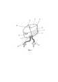
На фиг. 1 изображен беспроводной эпикардиальный ЭКС, где корпус 1, блок электроники 2, гальванический источник питания 3, электромеханический МЭМС-преобразователь 4, скобы для фиксации 5, электрод 6, гермовод 7, электроды стимуляции 8 и 9.In FIG. 1 shows a wireless epicardial EX, where
На фиг. 2 изображен электромеханический преобразователь, где инерционная масса в виде сектора 10, вращающийся вал 11, ведущее зубчатое колесо 12, ведомое колесо 13, ротор 14, ведомый вал 15, статор 16, катушка 17.In FIG. 2 shows an electromechanical converter, where the inertial mass in the form of a
На фиг. 3 и фиг. 4 показано расположение беспроводного эпикардиального ЭКС на эпикарде.In FIG. 3 and FIG. 4 shows the location of the wireless epicardial EX on the epicardium.
Устройство работает следующим образом.The device operates as follows.
В условиях кардиохирургической операционной на работающем сердце проводят эпикардиальную имплантацию устройства из миниторакотомного доступа (или срединной стернотомии) под общим наркозом. В момент имплантации выполняют вкручивание корпуса ЭКС на 2,5-3 оборота в межсосудистую область эпикарда, далее - дополнительную фиксацию устройства путем подшивания скоб 4 проленовыми лигатурами (нитями). Блок электроники 2 обеспечивает работу стимулятора в однокамерном или двухкамерном режимах. Спиральные электроды 8 и 9 регистрируют электрические потенциалы, поступающие с кардиомиоцитов эпикарда непосредственно в блок электроники 2. Блок электроники 2 анализирует сигнал, и если электрический сигнал собственной активности сердца не поступил, выдает через электрод 8 (в случае двухкамерной стимуляции также и через электрод 9) стимулирующий импульс для навязывания сокращения сердца. Электромеханический МЭМС-преобразователь 4 по принципу действия относится к электрическому генератору переменного тока. Инерционная масса в виде сектора 10 жестко закреплена на вращающемся валу 11, также на валу закреплено ведущее зубчатое колесо 12, которое в зацеплении с ведомым колесом 13 образует мультипликатор. Зубчатое колесо 13 и ротор 14 жестко закреплены на ведомом валу 15 и вращаются синхронно. Ротор 14 расположен в зазоре магнитопровода статора 16. Отклонение сектора на некоторый угол относительно начального положения вследствие воздействия сил ускорения или изменения положения тела пациента вызывает поворот ведущего колеса 12 и ведомого 13 с ротором 14. Вращающийся магнитный ротор вызывает изменение магнитного потока через катушку 17 статора и индуцирует в ее витках электродвижущую силу магнитной индукции. Выход преобразователя соединен с блоком электроники ЭКС, где напряжение переменного тока преобразуется в постоянное и используется для питания ЭКС.Under the conditions of a cardiosurgical operating room, an epicardial implantation of a device from a minithoracotomy access (or median sternotomy) under general anesthesia is performed on a working heart. At the time of implantation, the ECS case is screwed in 2.5-3 turns into the intervascular region of the epicardium, then the device is additionally fixed by stitching the staples with 4 worn ligatures (threads). The
Пример.Example.
Корпус эпикардиального ЭКС выполнен из титана, что обеспечивает биосовместимость с тканями организма. Корпус имеет форму цилиндра с диаметром, превышающим его высоту; диаметр основания 30 мм, высота 6,5 мм, масса 14 г. При таком соотношении основания и высоты удельная нагрузка на эпикард не вызывает его травмирования. Диаметр корпуса ЭКС определяется принципом функционирования электромеханического МЭМС-преобразователя, эффективность которого прямо пропорциональна моменту инерции инерционной массы (маятника). Момент инерции есть произведение массы на квадрат расстояния. Таким образом, увеличить момент маятника и, следовательно, эффективность МЭМС-преобразователя можно увеличением массы маятника или его длины, что более предпочтительно ввиду квадратичной зависимости. Увеличение массы нежелательно, поскольку это вызывает пропорциональное увеличение массы ЭКС, что увеличивает нагрузку на эпикард и может привести к его травмированию.The body of the epicardial EX is made of titanium, which ensures biocompatibility with body tissues. The body has the shape of a cylinder with a diameter exceeding its height; base diameter 30 mm, height 6.5 mm, weight 14 g. With this ratio of base and height, the specific load on the epicardium does not cause injury. The diameter of the ECS housing is determined by the principle of operation of the electromechanical MEMS converter, the efficiency of which is directly proportional to the moment of inertia of the inertial mass (pendulum). The moment of inertia is the product of mass and the square of the distance. Thus, the moment of the pendulum and, therefore, the efficiency of the MEMS converter can be increased by increasing the mass of the pendulum or its length, which is more preferable in view of the quadratic dependence. The increase in mass is undesirable, since this causes a proportional increase in the mass of EX, which increases the load on the epicardium and can lead to injury.
Работоспособность полезной модели подтверждается испытаниями, при которых на стенде имитации сокращений закреплялся МЭМС-преобразователь и имитировалось перемещение эпикарда за сердечный цикл. При этом сила тока, развиваемая преобразователем, варьировала в диапазоне 7-12 мкА при напряжении 3,5 В, что превышает потребление блока электроники, переводя основной источник питания (гальваническую батарею) в дежурный режим. В этом случае электропитание осуществляется от МЭМС-преобразователя, а снижение уровня заряда батареи определяется саморазрядом.The efficiency of the utility model is confirmed by tests, in which a MEMS transducer was fixed on the simulator of contractions and the epicardium was simulated during the cardiac cycle. At the same time, the current developed by the converter varied in the range of 7-12 μA at a voltage of 3.5 V, which exceeds the consumption of the electronics unit, putting the main power source (galvanic battery) in standby mode. In this case, power is supplied from the MEMS converter, and the decrease in battery level is determined by self-discharge.
Claims (1)
Translated fromRussianPriority Applications (1)
| Application Number | Priority Date | Filing Date | Title |
|---|---|---|---|
| RU2019145214URU197853U1 (en) | 2019-12-30 | 2019-12-30 | WIRELESS EPICARDIAL ELECTROCARDIAC PERIODIC STIMULATOR FOR TREATMENT OF BRADIARTHY AND HEART FAILURE |
Applications Claiming Priority (1)
| Application Number | Priority Date | Filing Date | Title |
|---|---|---|---|
| RU2019145214URU197853U1 (en) | 2019-12-30 | 2019-12-30 | WIRELESS EPICARDIAL ELECTROCARDIAC PERIODIC STIMULATOR FOR TREATMENT OF BRADIARTHY AND HEART FAILURE |
Publications (1)
| Publication Number | Publication Date |
|---|---|
| RU197853U1true RU197853U1 (en) | 2020-06-02 |
Family
ID=71066923
Family Applications (1)
| Application Number | Title | Priority Date | Filing Date |
|---|---|---|---|
| RU2019145214URU197853U1 (en) | 2019-12-30 | 2019-12-30 | WIRELESS EPICARDIAL ELECTROCARDIAC PERIODIC STIMULATOR FOR TREATMENT OF BRADIARTHY AND HEART FAILURE |
Country Status (1)
| Country | Link |
|---|---|
| RU (1) | RU197853U1 (en) |
Citations (4)
| Publication number | Priority date | Publication date | Assignee | Title |
|---|---|---|---|---|
| WO2004073138A1 (en)* | 2003-02-12 | 2004-08-26 | Medtronic Inc. | Self-powered implantable element |
| US20090299447A1 (en)* | 2005-07-01 | 2009-12-03 | Marc Jensen | Deployable epicardial electrode and sensor array |
| RU123269U1 (en)* | 2012-04-18 | 2012-12-20 | Федеральное государственное бюджетное образовательное учреждение высшего профессионального образования "Национальный исследовательский университет "МЭИ" (ФГБОУ ВПО "НИУ "МЭИ") | REVERSIBLE ELECTROSTATIC ROTATION MOTOR |
| US20140303688A1 (en)* | 2011-11-02 | 2014-10-09 | Haluk Kulah | Energy harvesting cochlear implant |
- 2019
- 2019-12-30RURU2019145214Upatent/RU197853U1/enactiveIP Right Revival
Patent Citations (4)
| Publication number | Priority date | Publication date | Assignee | Title |
|---|---|---|---|---|
| WO2004073138A1 (en)* | 2003-02-12 | 2004-08-26 | Medtronic Inc. | Self-powered implantable element |
| US20090299447A1 (en)* | 2005-07-01 | 2009-12-03 | Marc Jensen | Deployable epicardial electrode and sensor array |
| US20140303688A1 (en)* | 2011-11-02 | 2014-10-09 | Haluk Kulah | Energy harvesting cochlear implant |
| RU123269U1 (en)* | 2012-04-18 | 2012-12-20 | Федеральное государственное бюджетное образовательное учреждение высшего профессионального образования "Национальный исследовательский университет "МЭИ" (ФГБОУ ВПО "НИУ "МЭИ") | REVERSIBLE ELECTROSTATIC ROTATION MOTOR |
Similar Documents
| Publication | Publication Date | Title |
|---|---|---|
| US10398904B2 (en) | Energy harvesting mechanism for medical devices | |
| US20050256549A1 (en) | Micro-generator implant | |
| US5749909A (en) | Transcutaneous energy coupling using piezoelectric device | |
| EP2525870B1 (en) | Physiologically responsive vad | |
| US20040073267A1 (en) | Micro-generator implant | |
| US10905890B2 (en) | Autonomous cardiac implant of the leadless capsule type with energy harvester and controlled-charge energy storage buffer | |
| US20070293895A1 (en) | Acoustically-powered wireless defibrillator | |
| CN108310649B (en) | Self-powered wireless pacemaker with charging management technology | |
| CN101612451A (en) | Chargeable implant cardiac pacemaker device and charging method thereof | |
| Arzuaga | Cardiac pacemakers: Past, present and future | |
| HUP0004856A2 (en) | Device for augmentation of electrical conduction and contractility by biphasic cardiac pacing | |
| Senning | Cardiac pacing in retrospect | |
| RU197853U1 (en) | WIRELESS EPICARDIAL ELECTROCARDIAC PERIODIC STIMULATOR FOR TREATMENT OF BRADIARTHY AND HEART FAILURE | |
| CN201437021U (en) | Chargeable implanted cardiac pacemaker system | |
| CN110740779A (en) | Cardiac pacemaker with pacing pulse energy modulation based on sensed heart rate | |
| CN107929943B (en) | wireless charging pacemaker | |
| FURMAN et al. | Rechargeable pacemaker for direct myocardial implantation | |
| Bolz | Cardiac pacemaker systems | |
| RU143968U1 (en) | WIRELESS EPICARDIAL ELECTROCARDIAC STIMULATOR FOR TREATMENT OF BRADIARhythmias | |
| CN111407263A (en) | An implantable medical device fixing component | |
| Bockeria et al. | Potential Use of Heart Contractions as a Source of Energy for Implantable Devices | |
| Bockeria et al. | Conversion of Cardiac Contractions into Electrical Energy Using an Epicardial Wireless Pacemaker | |
| Starr et al. | Ventricular tracking pacemaker and teletransmitter follow-up system | |
| RU116356U1 (en) | Pacemaker for the treatment of bradyarrhythmias | |
| SU648231A1 (en) | Electrocardiostimulator |
Legal Events
| Date | Code | Title | Description |
|---|---|---|---|
| MM9K | Utility model has become invalid (non-payment of fees) | Effective date:20210510 | |
| TK9K | Obvious and technical errors in the register or in publications corrected via the gazette [utility model] | Free format text:CORRECTION TO CHAPTER -MM9K- IN JOURNAL 24-2021 | |
| NF9K | Utility model reinstated | Effective date:20210907 | |
| QB9K | Licence granted or registered (utility model) | Free format text:LICENCE FORMERLY AGREED ON 20210908 Effective date:20210908 |