RU193265U1 - DEVICE FOR WEIGHTED MULTIPLEXING OF SIGNALS IN THE FIFTH GENERATION WIRELESS COMMUNICATION SYSTEM - Google Patents
DEVICE FOR WEIGHTED MULTIPLEXING OF SIGNALS IN THE FIFTH GENERATION WIRELESS COMMUNICATION SYSTEMDownload PDFInfo
- Publication number
- RU193265U1 RU193265U1RU2018146257URU2018146257URU193265U1RU 193265 U1RU193265 U1RU 193265U1RU 2018146257 URU2018146257 URU 2018146257URU 2018146257 URU2018146257 URU 2018146257URU 193265 U1RU193265 U1RU 193265U1
- Authority
- RU
- Russia
- Prior art keywords
- multiplexing
- signal
- time
- signals
- block
- Prior art date
Links
- 238000004891communicationMethods0.000titleclaimsabstractdescription4
- 230000005540biological transmissionEffects0.000abstractdescription6
- 238000010586diagramMethods0.000description4
- 238000012545processingMethods0.000description4
- 238000012546transferMethods0.000description4
- 239000000872bufferSubstances0.000description3
- 125000004122cyclic groupChemical group0.000description3
- 230000001934delayEffects0.000description3
- 238000005516engineering processMethods0.000description3
- 238000013461designMethods0.000description1
- 238000011161developmentMethods0.000description1
- 238000006073displacement reactionMethods0.000description1
- 238000000034methodMethods0.000description1
- 230000005855radiationEffects0.000description1
Images


Classifications
- H—ELECTRICITY
- H04—ELECTRIC COMMUNICATION TECHNIQUE
- H04J—MULTIPLEX COMMUNICATION
- H04J4/00—Combined time-division and frequency-division multiplex systems
- H—ELECTRICITY
- H04—ELECTRIC COMMUNICATION TECHNIQUE
- H04W—WIRELESS COMMUNICATION NETWORKS
- H04W16/00—Network planning, e.g. coverage or traffic planning tools; Network deployment, e.g. resource partitioning or cells structures
- H04W16/14—Spectrum sharing arrangements between different networks
- H—ELECTRICITY
- H04—ELECTRIC COMMUNICATION TECHNIQUE
- H04W—WIRELESS COMMUNICATION NETWORKS
- H04W72/00—Local resource management
- H04W72/04—Wireless resource allocation
- H04W72/044—Wireless resource allocation based on the type of the allocated resource
- H04W72/0446—Resources in time domain, e.g. slots or frames
Landscapes
- Engineering & Computer Science (AREA)
- Computer Networks & Wireless Communication (AREA)
- Signal Processing (AREA)
- Mobile Radio Communication Systems (AREA)
Abstract
Translated fromRussianDescription
Translated fromRussianКРАТКОЕ ОПИСАНИЕ ЧЕРТЕЖЕЙBRIEF DESCRIPTION OF THE DRAWINGS
Некоторые варианты осуществления полезной модели описываются ниже со ссылками на прилагаемые фигуры.Some embodiments of the utility model are described below with reference to the accompanying figures.
Фигура 1 - схема предлагаемого мультиплексора.Figure 1 - diagram of the proposed multiplexer.
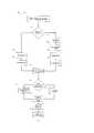
Фигура 2 - диаграмма, описывающая принцип работы мультиплексора.Figure 2 is a diagram describing the principle of operation of the multiplexer.
Фигура 3 - пример мультиплексирования OFDM сигналов.Figure 3 is an example of multiplexing OFDM signals.
УРОВЕНЬ ТЕХНИКИBACKGROUND
Аналогом данного технического решения является СПОСОБ И УСТРОЙСТВО ДЛЯ УПРАВЛЕНИЯ МНОЖЕСТВОМ ЛОГИЧЕСКИХ ПОТОКОВ ДАННЫХ В ОКРУЖЕНИИ С ПЕРЕМЕННОЙ СКОРОСТЬЮ ПЕРЕДАЧИ ДАННЫХ (свидетельство на полезную модель RU 2285349 С2, заявка 2004101288/09 от 21.05.2002 г., опубликовано 10.10.2006 г., правообладатель МОТОРОЛА, ИНК. (US), авторы ПЕСЕН Марк Эдвард (US)). Недостатками приведенного аналога являются его малые функциональные возможности, не позволяющие осуществить передачу трафика, для которого нужна сверхнадежная передача с минимальными задержками, что является критичным для сетей пятого поколения.An analogue of this technical solution is the METHOD AND DEVICE FOR MANAGING A LOT OF LOGIC DATA FLOWS IN THE ENVIRONMENT WITH A VARIABLE DATA TRANSFER SPEED (certificate for utility model RU 2285349 C2, application 2004101288/09 dated May 21, 2002, MO, published in July 10, 2002, MO2, , INC. (US), authors SESEN Mark Edward (US)). The disadvantages of this analogue are its small functionality, which does not allow the transmission of traffic, which requires ultra-reliable transmission with minimal delays, which is critical for fifth-generation networks.
Целью данного технического решения является расширение функциональных возможностей, обеспечение требуемой задержки для передачи трафика, для которого нужна сверхнадежная передача с минимальными задержками.The purpose of this technical solution is to expand the functionality, providing the required delay for the transmission of traffic, which requires ultra-reliable transmission with minimal delays.
ОПИСАНИЕ УСТРОЙСТВАDESCRIPTION OF THE DEVICE
На фигуре 1 изображена схема мультиплексора 101, состоящего из интерфейса ввода 121, предназначенного для приема синфазной и квадратурной составляющих (IQ) сигналов от передающих устройств 102, 103 и 104, а также для передачи управляющей информации о приоритете данных, типе трафика, расстоянии между поднесущими, назначении частотно-временных ресурсов различным блокам информации, приоритете каждого блока, ограничения по мощности, допустимую вероятность потери каждого блока и прочей необходимой информации. Также, через интерфейс ввода 121, может передаваться в обратном направлении информация о результате мультиплексирования передающим устройствам.The figure 1 shows a diagram of a
В качестве входного интерфейса может быть улучшенный общий открытый радиоинтерфейс (evolved Common Public Radio Interface, eCPRI), который является развитием общего открытого радиоинтерфейса, используемого для связи между функциональными блоками базовой станции. Входной интерфейс может принимать цифровой сигнал различных типов, в том числе OFDM сигнал в частотной или временной областях. Для приема OFDM сигнала на входной интерфейс должна поступать управляющая информация о параметрах OFDM сигнала, таких как расстояние между поднесущими, количество поднесущих и длительность циклического префикса.As an input interface, there may be an evolved Common Public Radio Interface (eCPRI), which is a development of a common open radio interface used for communication between functional units of a base station. The input interface can receive various types of digital signals, including the OFDM signal in the frequency or time domain. To receive an OFDM signal, control information about the parameters of the OFDM signal, such as the distance between subcarriers, the number of subcarriers, and the cyclic prefix length, must be received at the input interface.
Количество подключенных передающих устройств определяется количеством выходных интерфейсов 121. Также мультиплексор обладает центральным процессором 122 и памятью 123, необходимой для буферизации принимаемого сигнала от интерфейса 121. Для минимизации задержек при обработки входящих сигналов от интерфейса 121 и цифровой обработки данных сигналов в мультиплексоре предусмотрена Программируемая Логическая Интегральная Схема (ПЛИС) 124, содержащая необходимый функционал для работы мультиплексора. Ввиду того, что архитектура ПЛИС позволяет проектировать системы цифровой обработки данных, выполняющие множество вычислений параллельно, время обработки входного сигнала снижается, что позволяет производить сложение нескольких сигналов от разных передающих устройств в режиме реального времени.The number of connected transmitting devices is determined by the number of
Также мультиплексор имеет выходной интерфейс 125 для получения информации о состоянии канала для каждого пользователя и передаче обработанного цифрового сигнала, получившегося в результате действий мультиплексора над сигналами, полученными от передающих устройств 1…N. Выходной интерфейс может обладать цифро-аналоговым преобразователем (ЦАП) для преобразования результирующего цифрового сигнала в аналоговый и непосредственной передачи его на излучающую антенну.The multiplexer also has an
Входные интерфейсы, выходной интерфейс, память и центральный процессор соединены с ПЛИС шинами передачи данных.The input interfaces, the output interface, the memory and the central processor are connected to the FPGA data transfer buses.
На фигуре 2 изображена диаграмма, иллюстрирующая основные операции 200 мультиплексора при получении нескольких потоков данных от передаваемых устройств. При получении IQ сигнала (блок 201) от каждого передающего устройства мультиплексор определяет в частотном или временном виде представлен входящий IQ сигнал (блок 202). При временном представлении сигнала мультиплексор, получив контрольную информацию о параметрах сигнала удаляет циклический префикс (блок 203) и переводит сигнал в частотную область с помощью преобразования Фурье (блок 204). Затем, мультиплексор буфферизует сигнал (блоки 205 и 206) в частотной области для синхронизации IQ потоков и составления Виртуальной Ресурсной Решетки (блоки 207 и 208). На основе информации о состоянии канала, полученной от интерфейса ввода/вывода мультиплексор определяет допустимо ли при текущем состоянии канала использовать суперпозицию сигналов (блок 210). Если данная операция допустима, мультиплексор осуществляет суперпозицию сигналов (блок 212), предварительно изменяя мощности сигналов согласно текущему каналу. Изменение мощности сигнала может происходить с помощью умножения сигналов на весовой коэффициент, который выбирается в промежутке от 0 до 1, определяющий какую долю от всей мощности излучения получает данный сигнал, пришедший от одного из передающих устройств. Данный весовой коэффициент определяется исходя из качества канала между передающим устройством, включающим себя устройство для мультиплексирования, и принимающими устройствами. Если же суперпозиция каналов недопустима, мультиплексор замещает сегменты ВРР, принадлежащие сигналу с меньшим приоритетом сегментами ВРР, принадлежащим сигналу с большим приоритетом (блок 211) и передает информацию о вытеснении данного сегмента передающему устройству, который сгенерировал данный IQ сигнал. После вытеснения или суперпозиции поданных на мультиплексор сигналов, происходит обратное преобразование Фурье (блок 213). После добавления циклического префикса (блок 214) мультиплексор передает обработанный IQ сигнал на интерфейс ввода/вывода.Figure 2 is a diagram illustrating the basic operations of a
ПРИМЕРEXAMPLE
Рассмотрим пример использования мультиплексора при возникновении коллизий частотно временных ресурсов, которые используют технологии, основанные на передаче OFDM сигналов. Для обеспечения гибкости и независимости от технологии радиодоступа мультиплексор принимает на вход синфазную и квадратурную составляющие сигналов в частотной области, или во временной области от нескольких источников, которые могут использовать различные технологии радиодоступа. В случае, если один из входных потоков отсчетов представляет собой синфазную и квадратурную составляющие сигнала во временной области, мультиплексор с помощью преобразования Фурье переводит входящий сигнал в частотную область. Затем, каждый входящий поток от каждого передающего устройства мультиплексор располагает на виртуальной ресурсной решетке (ВРР), каждая из которых помещается в буфер. Данное представление выделенных ресурсов позволяет удобным образом разрешить коллизию потоков. В случае коллизии одного или нескольких секторов решетки мультиплексор может применить операцию вытеснения данных, обладающих меньшим приоритетом или же применить операцию суперпозиции если каналы между передатчиком и каждым пользователем, для которых данные предназначены подходящие. Фигура 3 иллюстрирует коллизию потоков еМВВ 301 и URLLC 302. Заштрихованная область 311 соответствует ВРР еМВВ трафика, в то время как заштрихованная область 312 соответствует ВРР URLLC трафика. Информация о занятых ВРР передается в распределитель ресурсов (мультиплексор) 303, результатом которого является ВРР 304. Поскольку ВРР еМВВ и URLLC потоков пересекаются, и приоритет URLLC потока выше, чем приоритет еМВВ потока (информация о приоритете получена с помощью контрольной информации по eCPRI интерфейсу) мультиплексор принимает решение о вытеснении сегментов, принадлежащих еМВВ потоку сегментами URLLC потока.Let us consider an example of using a multiplexer in the event of a collision of the frequency-time resources, which use technologies based on the transmission of OFDM signals. To provide flexibility and independence from radio access technology, the multiplexer receives in-phase and quadrature components of the signals in the frequency domain, or in the time domain, from several sources that can use various radio access technologies. If one of the input sample streams represents the in-phase and quadrature components of the signal in the time domain, the multiplexer, using the Fourier transform, transfers the input signal to the frequency domain. Then, each input stream from each transmitting device, the multiplexer is located on a virtual resource grating (VRP), each of which is placed in a buffer. This presentation of allocated resources allows you to conveniently resolve thread collisions. In the event of a collision of one or several sectors of the grating, the multiplexer can apply the operation of crowding out data with lower priority or apply the operation of superposition if the channels between the transmitter and each user for which the data is intended are suitable. Figure 3 illustrates the collision of the streams eMBB 301 and URLLC 302. The hatched
Claims (4)
Translated fromRussianPriority Applications (1)
| Application Number | Priority Date | Filing Date | Title |
|---|---|---|---|
| RU2018146257URU193265U1 (en) | 2018-12-25 | 2018-12-25 | DEVICE FOR WEIGHTED MULTIPLEXING OF SIGNALS IN THE FIFTH GENERATION WIRELESS COMMUNICATION SYSTEM |
Applications Claiming Priority (1)
| Application Number | Priority Date | Filing Date | Title |
|---|---|---|---|
| RU2018146257URU193265U1 (en) | 2018-12-25 | 2018-12-25 | DEVICE FOR WEIGHTED MULTIPLEXING OF SIGNALS IN THE FIFTH GENERATION WIRELESS COMMUNICATION SYSTEM |
Publications (1)
| Publication Number | Publication Date |
|---|---|
| RU193265U1true RU193265U1 (en) | 2019-10-21 |
Family
ID=68315563
Family Applications (1)
| Application Number | Title | Priority Date | Filing Date |
|---|---|---|---|
| RU2018146257URU193265U1 (en) | 2018-12-25 | 2018-12-25 | DEVICE FOR WEIGHTED MULTIPLEXING OF SIGNALS IN THE FIFTH GENERATION WIRELESS COMMUNICATION SYSTEM |
Country Status (1)
| Country | Link |
|---|---|
| RU (1) | RU193265U1 (en) |
Cited By (1)
| Publication number | Priority date | Publication date | Assignee | Title |
|---|---|---|---|---|
| CN114978836A (en)* | 2022-04-25 | 2022-08-30 | 北京邮电大学 | Detection and communication integrated method and electronic equipment |
Citations (5)
| Publication number | Priority date | Publication date | Assignee | Title |
|---|---|---|---|---|
| WO1999043112A1 (en)* | 1998-02-19 | 1999-08-26 | Gte Internetworking Incorporated | Method and apparatus for byte-by-byte multiplexing of data over parallel communication links |
| US7394753B2 (en)* | 1995-02-06 | 2008-07-01 | Adc Telecommunications Inc. | Training premable in multipoint-to-point communication using orthogonal frequency division multiplexing |
| US7424268B2 (en)* | 2002-04-22 | 2008-09-09 | Cisco Technology, Inc. | System and method for management of a shared frequency band |
| US8462817B2 (en)* | 2003-10-15 | 2013-06-11 | Qualcomm Incorporated | Method, apparatus, and system for multiplexing protocol data units |
| RU2548037C2 (en)* | 2010-11-02 | 2015-04-10 | Квэлкомм Инкорпорейтед | Protocols for enabling mode 1 and mode 2 devices in tv white space networks |
- 2018
- 2018-12-25RURU2018146257Upatent/RU193265U1/enactive
Patent Citations (5)
| Publication number | Priority date | Publication date | Assignee | Title |
|---|---|---|---|---|
| US7394753B2 (en)* | 1995-02-06 | 2008-07-01 | Adc Telecommunications Inc. | Training premable in multipoint-to-point communication using orthogonal frequency division multiplexing |
| WO1999043112A1 (en)* | 1998-02-19 | 1999-08-26 | Gte Internetworking Incorporated | Method and apparatus for byte-by-byte multiplexing of data over parallel communication links |
| US7424268B2 (en)* | 2002-04-22 | 2008-09-09 | Cisco Technology, Inc. | System and method for management of a shared frequency band |
| US8462817B2 (en)* | 2003-10-15 | 2013-06-11 | Qualcomm Incorporated | Method, apparatus, and system for multiplexing protocol data units |
| RU2548037C2 (en)* | 2010-11-02 | 2015-04-10 | Квэлкомм Инкорпорейтед | Protocols for enabling mode 1 and mode 2 devices in tv white space networks |
Cited By (2)
| Publication number | Priority date | Publication date | Assignee | Title |
|---|---|---|---|---|
| CN114978836A (en)* | 2022-04-25 | 2022-08-30 | 北京邮电大学 | Detection and communication integrated method and electronic equipment |
| CN114978836B (en)* | 2022-04-25 | 2023-12-29 | 北京邮电大学 | Detection communication integrated method and electronic equipment |
Similar Documents
| Publication | Publication Date | Title |
|---|---|---|
| CN110838903B (en) | Method, terminal, base station and computer storage medium for uplink transmission indication | |
| US20190260549A1 (en) | Unified flexible radio access technology (rat) for 5g mobile communication systems | |
| US11303489B2 (en) | Transmitting apparatus, receiving apparatus, transmitting method, and receiving method | |
| WO2004031918A2 (en) | Method to convey uplink traffic information | |
| JP6356819B2 (en) | Uplink access method, apparatus, and system | |
| WO2015054162A1 (en) | Systems and methods for delay management in distributed antenna system with direct digital interface to base station | |
| JP7130737B2 (en) | Reference signal transmission method, device, base station and terminal | |
| JP2020523861A (en) | Mapping instruction apparatus and method in mixed OFDM numerology | |
| CN110536439A (en) | Method, apparatus, user equipment, base station and the storage medium of resource distribution | |
| US11515988B2 (en) | Method and device for determining initial positions of downlink data channel | |
| CN106954277A (en) | A kind of dispatch request treating method and apparatus | |
| US12199804B2 (en) | Communication method, apparatus, and device | |
| CN109792727A (en) | Communication means, terminal and the network equipment | |
| RU193265U1 (en) | DEVICE FOR WEIGHTED MULTIPLEXING OF SIGNALS IN THE FIFTH GENERATION WIRELESS COMMUNICATION SYSTEM | |
| CN107872804A (en) | A data transmission method and device | |
| CN111565458B (en) | Downlink transmission method and device thereof | |
| CN108134624A (en) | A kind of reference signal sending, receiving method, transmitting terminal and receiving terminal | |
| CN112566010B (en) | Signal sending and receiving method, network equipment and terminal equipment | |
| CN114424639A (en) | Signal transmission method, device and communication system | |
| CN109219052A (en) | A kind of resource information transfer method, relevant device and system | |
| JP2021513799A (en) | Resource allocation for configurable bandwidth | |
| CN110268728B (en) | Data transmission method, device and system | |
| WO2020214087A1 (en) | Communication apparatuses and communication methods for soft-segregation of resource pool for v2x communication apparatuses | |
| Casellas et al. | On-demand allocation of control plane functions via SDN/NFV for monitoring-enabled flexi-grid optical networks with programmable BVTs | |
| JP2000269927A (en) | OFDM signal delay device and OFDM signal transmission device including the same |