RU191279U1 - RJ-45 Network Interface Contact Checker - Google Patents
RJ-45 Network Interface Contact CheckerDownload PDFInfo
- Publication number
- RU191279U1 RU191279U1RU2018125051URU2018125051URU191279U1RU 191279 U1RU191279 U1RU 191279U1RU 2018125051 URU2018125051 URU 2018125051URU 2018125051 URU2018125051 URU 2018125051URU 191279 U1RU191279 U1RU 191279U1
- Authority
- RU
- Russia
- Prior art keywords
- microcontroller
- cable
- contacts
- network interface
- socket
- Prior art date
Links
Images

Classifications
- H—ELECTRICITY
- H04—ELECTRIC COMMUNICATION TECHNIQUE
- H04B—TRANSMISSION
- H04B3/00—Line transmission systems
- H04B3/02—Details
- H04B3/46—Monitoring; Testing
Landscapes
- Engineering & Computer Science (AREA)
- Computer Networks & Wireless Communication (AREA)
- Signal Processing (AREA)
- Testing Of Short-Circuits, Discontinuities, Leakage, Or Incorrect Line Connections (AREA)
Abstract
Translated fromRussianDescription
Translated fromRussianПолезная модель относится к области электротехники и может быть использована в телекоммуникационных сетях и предназначена для поиска неисправностей в ближней зоне «патч корд, патч панель и телекоммуникационный шкаф».The utility model relates to the field of electrical engineering and can be used in telecommunication networks and is intended for troubleshooting in the near zone “patch cord, patch panel and telecommunication cabinet”.
Существующие измерители длины кабеля используют рефлектометры или измеряют сопротивления кабеля. Подобные устройства характерны технической сложностью и высокой стоимостью. При этом, схема работы известных устройств требует отсутствия на другом конце кабеля соединения с активным оборудованием, либо же предусматривает дополнительного подключения согласованной нагрузки («терминатора»).Existing cable length meters use reflectometers or measure cable resistance. Such devices are characterized by technical complexity and high cost. At the same time, the operation scheme of known devices requires the absence of a connection to active equipment at the other end of the cable, or provides for an additional connection of the agreed load (“terminator”).
Например, известно устройство для измерения длины кабеля (см. RU №2017331, кл. Н04В 3/46, опубл. 30.07.1994), содержащее последовательно соединенные индукционный датчик, усилитель, умножитель частоты, фазовый детектор, аналого-цифровой преобразователь, индикатор, генератор прямоугольных импульсов и широкополосный усилитель. Данное устройство также требует подключения к обоим концам кабеля.For example, a device is known for measuring cable length (see RU No. 2017331, CL HB04/46, publ. 07/30/1994), containing a series-connected induction sensor, amplifier, frequency multiplier, phase detector, analog-to-digital converter, indicator, square wave generator and broadband amplifier. This device also requires connection to both ends of the cable.
Известно устройство проверки контактов сетевого интерфейса (см. US №7068043 В1, кл. G01R 31/11, опубл. 27.06.2006), содержащее испытательный модуль, включающий в своем составе контроллер, синтезатор частоты, индикатор и модуль тестирования, состоящий из считывающей схемы, эхоподавителя перекрестных помех и блока питания, работающее по принципу измерения расстояния до поврежденного участка способом рефлектометрии, т.е. отправляя импульсы, улавливает отраженный сигнал и, измеряя время задержки, определяет длину кабеля. Скорость сигнала близка к скорости света, что требует наличия высокоскоростного дорогостоящего оборудования, отличающегося, кроме того, сложностью в использовании и обслуживании.A device for checking the contacts of a network interface (see US No. 7068043 B1, class G01R 31/11, publ. 06/27/2006) is provided, which contains a test module including a controller, a frequency synthesizer, an indicator, and a test module, consisting of a readout circuit , an echo canceller of crosstalk and a power supply, operating on the principle of measuring the distance to the damaged area by reflectometry, i.e. sending pulses, it picks up the reflected signal and, measuring the delay time, determines the length of the cable. The signal speed is close to the speed of light, which requires the availability of high-speed expensive equipment, which is also distinguished by its complexity in use and maintenance.
Кроме того, известное устройство непригодно для использования емкостной связи между жилами, что было бы экономически выгоднее, т.к. рефлектометрический способ измерения неизбежно приводит к переотражению полезного сигнала и в случае, когда другой конец кабеля подключен к активному оборудованию, не будет способствовать получению явно выраженного отраженного сигнала.In addition, the known device is unsuitable for using capacitive coupling between the wires, which would be economically advantageous, because OTDR measurement inevitably leads to re-reflection of the useful signal and in the case when the other end of the cable is connected to active equipment, it will not contribute to the receipt of a pronounced reflected signal.
Задача настоящей полезной модели заключается в создании устройства для проверки контактов сетевого интерфейса, позволяющего оперативно определять местоположения повреждений в кабеле или сетевом интерфейсе.The objective of this utility model is to create a device for checking the contacts of the network interface, which allows you to quickly determine the location of damage in the cable or network interface.
Технический эффект, получаемый при решении поставленной задачи, выражается в обеспечении удобства использования устройства, обусловленного исключением при измерениях необходимости отключения кабеля от ранее присоединенного активного оборудования или же подключения дополнительной согласованной нагрузки.The technical effect obtained when solving the problem is expressed in ensuring the usability of the device, due to the exception when measuring the need to disconnect the cable from previously connected active equipment or to connect an additional agreed load.
Для решения поставленной задачи устройство проверки контактов для сетевого интерфейса стандарта RJ-45, в котором функции генератора импульса, аналого-цифрового преобразователя реализованы в микроконтроллере, запрограммированного на подачу импульса и измерение уровня импульса попеременно на всех измеряемых жилах тестируемого кабеля, причем вход микроконтроллера подключен к контактам розетки, а выход - к устройству визуального отображения информации, например, в виде дисплея, отличается тем, что для измерения величины наведенного напряжения на измеряемой жиле кабеля и в целях защиты микроконтроллера от электрических помех, электрическая цепь связи микроконтроллера с контактами розетки выполнена через сборку резисторов.To solve this problem, a contact checking device for the RJ-45 standard network interface, in which the functions of a pulse generator and an analog-to-digital converter are implemented in a microcontroller programmed to supply a pulse and measure the pulse level alternately on all measured conductors of the cable under test, and the input of the microcontroller is connected to the contacts of the outlet, and the output to the device for visual display of information, for example, in the form of a display, differs in that for measuring the magnitude of the induced voltage eniya measured on conductor cable and in order to protect the microcontroller from electrical noise, electrical connection microcontroller circuit with contacts formed through outlet assembly resistors.
Сопоставительный анализ признаков заявленного решения с известными признаками свидетельствует о соответствии заявленного решения критерию «новизна».A comparative analysis of the features of the claimed solution with known features indicates the conformity of the claimed solution to the criterion of "novelty."
Совокупность признаков полезной модели обеспечивает решение заявленной технической задачи, а именно, создание простейшего устройства, позволяющего тестировать и находить повреждения в кабельной сети или сетевом интерфейсе, причем, без необходимости отключения присоединенного активного оборудования.The combination of features of the utility model provides a solution to the claimed technical problem, namely, the creation of a simple device that allows testing and finding damage in a cable network or network interface, moreover, without the need to disconnect connected active equipment.
Заявляемое устройство измеряет величину наведенного напряжения на измеряемой жиле кабеля, зависящую от емкостной связи между жилами кабеля и индицирует полученные результаты в графическом виде на дисплее устройства. При этом для удобства работы, получаемые и отображаемые результаты, могут быть оформлены графическими элементами, иллюстрирующими длину измеряемых жил кабеля, например, в виде кратных черточек. Таким образом, легко отображается различие в длине жилы в случае неконтакта в патч корде и патч панели, в результате чего ориентировочно определяется местоположение повреждения кабеля. При этом исключается необходимость отключения кабеля от активного оборудовании или дополнительного подключения терминатора, что значительно упрощает использование устройства и способствует ускоренному выполнению поисковых работ.The inventive device measures the magnitude of the induced voltage on the measured cable core, depending on the capacitive coupling between the cable cores and displays the results in graphical form on the display of the device. At the same time, for the convenience of work, the results obtained and displayed can be decorated with graphic elements illustrating the length of the measured cable conductors, for example, in the form of multiple dashes. Thus, the difference in the length of the core in case of non-contact in the patch cord and patch panel is easily displayed, as a result of which the location of the cable damage is roughly determined. This eliminates the need to disconnect the cable from active equipment or additional connection of the terminator, which greatly simplifies the use of the device and contributes to the accelerated implementation of search operations.
Опытным путем установлено, что оптимальная длина для тестирования кабели составляет не более 10 м, что достаточно для диагностики ближней зоны, так как в дальней зоне на расстояниях, например, около 100 м, достоверность результатов измерений падает из-за большой погрешности измерений.It was experimentally established that the optimal length for testing cables is not more than 10 m, which is sufficient for the diagnosis of the near field, since in the far zone at distances, for example, about 100 m, the reliability of the measurement results decreases due to the large measurement error.
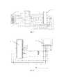
Заявленное устройство иллюстрируется чертежами, где на фиг. 1 показана схема соединения микроконтроллера и розетки (на примере RJ-45); на фиг. 2 - схема соединения микроконтроллера с дисплеем; на фиг. 3 - опытный образец устройства тестера.The claimed device is illustrated by drawings, where in FIG. 1 shows the connection diagram of the microcontroller and the socket (for example, RJ-45); in FIG. 2 - connection diagram of a microcontroller with a display; in FIG. 3 - a prototype device tester.
Основной модуль кабельного тестера включает розетку 1 типа RJ-45, микроконтроллер 2 типа PIC16F886, подключенные через сборку резисторов 4, дисплей 3 (например, для опытного образца был использован дисплей от телефона Nokia-5110) и цепи элементов. При этом питание осуществляется от известных элементов, обеспечивающих ток питания не более 1,5 mА, например, литиевой батарейки CR 2032.The main module of the cable tester includes an RJ-45
Принципиальные электрические схемы соединения микроконтроллера и розетки RJ-4 5, микроконтроллера с дисплеем - представлены на фигурах 1 и 2.Schematic diagrams of the connection of the microcontroller and the RJ-4 5 socket, the microcontroller with the display are presented in figures 1 and 2.
Управление микроконтроллером 2 осуществляется посредством специальной программы, составленной, например, на ассемблере контроллеров PIC фирмы Microchip Technology, управляющей режимом определения наличия каждого контакта в измеряемой розетке или коннекторе с кабелем. При необходимости, программа может применяться в режиме измерения соответствия стандарту обжима коннекторов и розеток RJ-45, например, для проверки перепутанности жил кабеля, для чего, дополнительно потребуется модуль в виде терминатора-заглушки.The control of
Работа заявленного устройства для проверки контактов сетевого интерфейса заключается в следующем.The operation of the claimed device for checking the contacts of the network interface is as follows.
Микроконтроллер 2 формирует измерительные импульсы на контактах розетки 1 длительностью около 50 мкс. Далее, на один из контактов розетки 1 микроконтроллер 2 подключает АЦП (аналогово-цифровой преобразователь) и измеряет затухающий потенциал фронта сигнала, который обусловлен дифференцирующей цепочкой, образованной между емкостью между проводниками и сопротивлением входа прибора. Микроконтроллер 2 поочередно осуществляет такие же измерения на всех контактах розетки 1, причем, выполняет те же процессы по установленному программой количеству повторных измерений, например, 10 раз.The
Максимальные значения полученных результатов микроконтроллер 2 выводит на индикацию дисплея 3, на котором графически отображается отсутствие или наличие контактов в определенной жиле на патч панели или розетке 1, например, в виде графических черточек, кратно иллюстрирующих длину измеряемых жил кабеля. По отображению различия в длине жил, в случаях отсутствия контакта в патч корде и патч панели, ориентировочно определяется местоположение повреждения кабеля в пределах измеряемой длины кабеля. При этом другой конец кабеля может быть отключен от активной нагрузки или подключен к любому устройству, например, с РоЕ (Power over Ethernet).The
Настоящая полезная модель может быть использована, например, в телекоммуникационных сетях для поиска неисправностей в ближней зоне «патч корд, патч панель и телекоммуникационный шкаф». Специалистом с помощью заявленного устройства может быть быстро и не сложным путем определено наличие и местоположение повреждений кабеля, отсутствие контактов в сетевом интерфейсе, а простота конструкции и использования тестера способствуют удешевлению и ускорению диагностических работ.This utility model can be used, for example, in telecommunication networks for troubleshooting in the near zone “patch cord, patch panel and telecommunications cabinet”. The specialist with the help of the claimed device can quickly and easily determine the presence and location of cable damage, the absence of contacts in the network interface, and the simplicity of the design and use of the tester contribute to cheaper and faster diagnostic work.
Claims (1)
Translated fromRussianPriority Applications (1)
| Application Number | Priority Date | Filing Date | Title |
|---|---|---|---|
| RU2018125051URU191279U1 (en) | 2018-07-10 | 2018-07-10 | RJ-45 Network Interface Contact Checker |
Applications Claiming Priority (1)
| Application Number | Priority Date | Filing Date | Title |
|---|---|---|---|
| RU2018125051URU191279U1 (en) | 2018-07-10 | 2018-07-10 | RJ-45 Network Interface Contact Checker |
Publications (1)
| Publication Number | Publication Date |
|---|---|
| RU191279U1true RU191279U1 (en) | 2019-08-01 |
Family
ID=67586061
Family Applications (1)
| Application Number | Title | Priority Date | Filing Date |
|---|---|---|---|
| RU2018125051URU191279U1 (en) | 2018-07-10 | 2018-07-10 | RJ-45 Network Interface Contact Checker |
Country Status (1)
| Country | Link |
|---|---|
| RU (1) | RU191279U1 (en) |
Cited By (1)
| Publication number | Priority date | Publication date | Assignee | Title |
|---|---|---|---|---|
| RU2803959C1 (en)* | 2023-02-09 | 2023-09-25 | Общество с ограниченной ответственностью "Сандракс" | Multifunctional modular software and hardware complex |
Citations (6)
| Publication number | Priority date | Publication date | Assignee | Title |
|---|---|---|---|---|
| US5414343A (en)* | 1992-07-28 | 1995-05-09 | Samuel J. Flaherty | Permanently installed cable system with integrated multi-cable tester |
| US5583874A (en)* | 1994-12-07 | 1996-12-10 | Infonet Computer Systems, Inc. | 10Base-T portable link tester |
| US7068043B1 (en)* | 2002-06-07 | 2006-06-27 | Marvell International Ltd. | Cable tester |
| US7808247B1 (en)* | 2007-02-22 | 2010-10-05 | Marvel International Ltd. | Fast cable tester |
| US7906973B1 (en)* | 2006-06-09 | 2011-03-15 | Marvell International Ltd. | Cable tester |
| RU2642478C2 (en)* | 2016-04-13 | 2018-01-25 | федеральное государственное автономное образовательное учреждение высшего образования "Самарский государственный аэрокосмический университет имени академика С.П. Королева (национальный исследовательский университет)" (СГАУ) | Automated control system of parameters of cable-bus networks of autonomous objects |
- 2018
- 2018-07-10RURU2018125051Upatent/RU191279U1/enactive
Patent Citations (6)
| Publication number | Priority date | Publication date | Assignee | Title |
|---|---|---|---|---|
| US5414343A (en)* | 1992-07-28 | 1995-05-09 | Samuel J. Flaherty | Permanently installed cable system with integrated multi-cable tester |
| US5583874A (en)* | 1994-12-07 | 1996-12-10 | Infonet Computer Systems, Inc. | 10Base-T portable link tester |
| US7068043B1 (en)* | 2002-06-07 | 2006-06-27 | Marvell International Ltd. | Cable tester |
| US7906973B1 (en)* | 2006-06-09 | 2011-03-15 | Marvell International Ltd. | Cable tester |
| US7808247B1 (en)* | 2007-02-22 | 2010-10-05 | Marvel International Ltd. | Fast cable tester |
| RU2642478C2 (en)* | 2016-04-13 | 2018-01-25 | федеральное государственное автономное образовательное учреждение высшего образования "Самарский государственный аэрокосмический университет имени академика С.П. Королева (национальный исследовательский университет)" (СГАУ) | Automated control system of parameters of cable-bus networks of autonomous objects |
Cited By (1)
| Publication number | Priority date | Publication date | Assignee | Title |
|---|---|---|---|---|
| RU2803959C1 (en)* | 2023-02-09 | 2023-09-25 | Общество с ограниченной ответственностью "Сандракс" | Multifunctional modular software and hardware complex |
Similar Documents
| Publication | Publication Date | Title |
|---|---|---|
| EP0681187B1 (en) | Instrument and method for testing local area network cables | |
| US6160405A (en) | Method and apparatus for remotely changing signal characteristics of a signal generator | |
| US9395399B2 (en) | Signal processing apparatuses and methods for identifying cable connections between ports | |
| US9124530B2 (en) | Apparatus for identifying interconnections and determining the physical state of cable lines in a network | |
| KR980010448A (en) | Method and apparatus for measuring shear crosstalk in patch cords | |
| US4277740A (en) | Cable tester for multipair cables | |
| JP2004529370A (en) | Failure detection system and method | |
| CN204731364U (en) | A kind of portable polycore cable distribution tester | |
| KR101496169B1 (en) | System and method for inspecting local area network cables | |
| CN109932614A (en) | A kind of cable fault troubleshooting method and device | |
| CN113447885B (en) | Electric energy meter wrong wiring rapid detection circuit and device | |
| US8570049B2 (en) | Method and apparatus for measuring AC shield continuity for shielded twisted pair structured datacomm cable link | |
| US6859041B2 (en) | Methods for locating faults in aircraft branch conductors and determining the distance to the faults | |
| CN101502087A (en) | Office ID remote with oscillating circuit | |
| CN205427089U (en) | Cable switches on insulation test device | |
| RU191279U1 (en) | RJ-45 Network Interface Contact Checker | |
| KR102597145B1 (en) | Diagnosis method of degradation about multiple cable and Diagnosis device of degradation about multiple cable | |
| CN101963641A (en) | Conductor bundle detection system | |
| CN102967796A (en) | Detecting method for short dot position of cable | |
| CN214409242U (en) | Cable fault tester | |
| RU2142142C1 (en) | Device locating point of fault in power transmission and communication lines | |
| CN208270635U (en) | Multifunctional test equipment | |
| CN210294418U (en) | Portable towrope detection equipment | |
| CN106053985B (en) | A kind of Power over Ethernet test device | |
| CN220526473U (en) | Cable fault simulation device |