RU188428U1 - SCREW FOR OSTEOSYNTHESIS OF THE FEMORAL NECK - Google Patents
SCREW FOR OSTEOSYNTHESIS OF THE FEMORAL NECKDownload PDFInfo
- Publication number
- RU188428U1 RU188428U1RU2018133910URU2018133910URU188428U1RU 188428 U1RU188428 U1RU 188428U1RU 2018133910 URU2018133910 URU 2018133910URU 2018133910 URU2018133910 URU 2018133910URU 188428 U1RU188428 U1RU 188428U1
- Authority
- RU
- Russia
- Prior art keywords
- rod
- screw
- intended
- proximal
- neck
- Prior art date
Links
- 210000002436femur neckAnatomy0.000titleclaimsabstractdescription11
- 210000000988bone and boneAnatomy0.000claimsabstractdescription27
- 238000009434installationMethods0.000claimsabstractdescription12
- 238000005520cutting processMethods0.000claimsabstractdescription11
- 238000010079rubber tappingMethods0.000claimsabstractdescription8
- 238000005553drillingMethods0.000claimsabstractdescription7
- 210000000527greater trochanterAnatomy0.000claimsabstractdescription4
- 229910052751metalInorganic materials0.000claimsdescription6
- 239000002184metalSubstances0.000claimsdescription6
- 229910001069Ti alloyInorganic materials0.000claimsdescription4
- 239000000463materialSubstances0.000claimsdescription4
- 238000005096rolling processMethods0.000claimsdescription3
- 206010017076FractureDiseases0.000abstractdescription8
- 208000020089femoral neck fractureDiseases0.000abstractdescription5
- 210000000689upper legAnatomy0.000abstractdescription5
- 238000005516engineering processMethods0.000abstractdescription3
- 230000000399orthopedic effectEffects0.000abstractdescription2
- 208000010392Bone FracturesDiseases0.000description7
- 230000006835compressionEffects0.000description7
- 238000007906compressionMethods0.000description7
- 239000012634fragmentSubstances0.000description5
- 238000000034methodMethods0.000description5
- 239000003814drugSubstances0.000description4
- 229940079593drugDrugs0.000description4
- 230000008569processEffects0.000description4
- 230000001054cortical effectEffects0.000description3
- 208000015181infectious diseaseDiseases0.000description3
- 239000010935stainless steelSubstances0.000description3
- 229910001220stainless steelInorganic materials0.000description3
- 241001661918BartoniaSpecies0.000description2
- 206010020100Hip fractureDiseases0.000description2
- 208000027418Wounds and injuryDiseases0.000description2
- 230000006378damageEffects0.000description2
- 230000004927fusionEffects0.000description2
- 208000014674injuryDiseases0.000description2
- 230000007935neutral effectEffects0.000description2
- 230000035515penetrationEffects0.000description2
- 230000008859changeEffects0.000description1
- 210000003414extremityAnatomy0.000description1
- 238000002513implantationMethods0.000description1
- 238000003780insertionMethods0.000description1
- 230000037431insertionEffects0.000description1
- 238000011900installation processMethods0.000description1
- 238000004519manufacturing processMethods0.000description1
- 230000007246mechanismEffects0.000description1
- 230000011164ossificationEffects0.000description1
- 229920001296polysiloxanePolymers0.000description1
- 210000004872soft tissueAnatomy0.000description1
- 230000000638stimulationEffects0.000description1
- 230000008719thickeningEffects0.000description1
Images


Classifications
- A—HUMAN NECESSITIES
- A61—MEDICAL OR VETERINARY SCIENCE; HYGIENE
- A61B—DIAGNOSIS; SURGERY; IDENTIFICATION
- A61B17/00—Surgical instruments, devices or methods
- A61B17/56—Surgical instruments or methods for treatment of bones or joints; Devices specially adapted therefor
- A61B17/58—Surgical instruments or methods for treatment of bones or joints; Devices specially adapted therefor for osteosynthesis, e.g. bone plates, screws or setting implements
- A61B17/68—Internal fixation devices, including fasteners and spinal fixators, even if a part thereof projects from the skin
- A61B17/74—Devices for the head or neck or trochanter of the femur
- A61B17/742—Devices for the head or neck or trochanter of the femur having one or more longitudinal elements oriented along or parallel to the axis of the neck
Landscapes
- Health & Medical Sciences (AREA)
- Orthopedic Medicine & Surgery (AREA)
- Surgery (AREA)
- Life Sciences & Earth Sciences (AREA)
- Heart & Thoracic Surgery (AREA)
- Nuclear Medicine, Radiotherapy & Molecular Imaging (AREA)
- Engineering & Computer Science (AREA)
- Biomedical Technology (AREA)
- Neurology (AREA)
- Medical Informatics (AREA)
- Molecular Biology (AREA)
- Animal Behavior & Ethology (AREA)
- General Health & Medical Sciences (AREA)
- Public Health (AREA)
- Veterinary Medicine (AREA)
- Surgical Instruments (AREA)
Abstract
Translated fromRussian
Description
Translated fromRussianОбласть техники.The field of technology.
Полезная модель относится к области медицинской техники, в частности к медицинским изделиям, применяемым в травматологии и ортопедии для остеосинтеза при переломе шейки бедренной кости.The invention relates to the field of medical technology, in particular to medical devices used in traumatology and orthopedics for osteosynthesis for fractures of the femoral neck.
Известен стержень-шуруп (источник [1]: патент RU 14826; Опубликовано: 10.09.2000) содержащий рабочую часть с винтовой нарезкой, ограниченную упорной площадкой, и крепежную часть. На крепежной части выполнен концентратор напряжения, расположенный в плоскости, перпендикулярной оси стержня-шурупа и расположенный между упорной площадкой и крепежным концом.Known rod-screw (source [1]: patent RU 14826; Published: 10.09.2000) containing a working part with a screw thread, limited to the thrust pad, and the mounting part. On the mounting part there is a voltage concentrator located in a plane perpendicular to the axis of the rod-screw and located between the support platform and the fixing end.
Известен стержень-шуруп к аппарату для чрескостного остеосинтеза (источник [2]: патент RU 19638; Опубликовано: 20.09.2001). Стержень-шуруп [2] содержит стержень, который снабжен конусным заостренным рабочим концом и крепежным концом. Рабочий конец имеет заострение, выполненное под углом 30 градусов, и конусовидный участок, на котором выполнена упорная трапецеидальная резьба (винтовая нарезка), кроме того, гладкий цилиндрический участок, а на крепежном конце выполнена резьба и участок, имеющий грани.Known rod-screw to the apparatus for transosseous osteosynthesis (source [2]: patent RU 19638; Published: 20.09.2001). The rod-screw [2] contains a rod that is provided with a tapered pointed working end and a fastening end. The working end has a taper, made at an angle of 30 degrees, and a cone-shaped section, on which a resistant trapezoidal thread (screw thread) is made, in addition, a smooth cylindrical section, and a thread and a section having edges on the fixing end.
Известен стержень - шуруп для аппарата внешней фиксации (источник [3]: патент RU 143507; Опубликовано: 27.07.2014). Стержень - шуруп [3] канюлированный представляет собой стержень, который состоит из самонарезающий и резьбоформирующей части с одной стороны, с другой стороны - резьбовой части и безрезьбового участка между ними. Внутри стержня имеется сквозное отверстие. На конце резьбовой части имеется концевой резиновый колпачок.Known rod - screw for external fixation device (source [3]: patent RU 143507; Published: 07.27.2014). The rod - the screw [3] cannulated is a rod that consists of a self-tapping and thread-forming part on the one hand, on the other hand a threaded part and a threadless section between them. Inside the core there is a through hole. At the end of the threaded part there is a rubber end cap.
Аналоги [1; 2; 3] не позволяют осуществлять динамическую компрессию на стыке между костными фрагментами в процессе ходьбы, так как выполнены монолитными. Конструкция винтов не обеспечивает возможность изменения длины, как при установке винтов, так и в процессе сращения перелома.Analogs [1; 2; 3] do not allow dynamic compression at the junction between the bone fragments in the process of walking, since they are made monolithic. The design of the screws does not provide the possibility of changing the length, both during the installation of the screws and in the process of the fracture fusion.
Известно устройство для остеосинтеза шейки бедра (источник [4]: патент RU 80333; Опубликовано: 10.02.2009). Устройство содержит основание, в котором фиксирован стержень, снабженный сквозным осевым каналом, внешней резьбовой нарезкой, минимум двумя раздвижными лопастями на рабочем конце и расположенным в центральной части граненым выступом, ограниченным буртиком. На выступе установлен поворотный ключ, соединенный посредством шарнира с закрепленной с помощью кронштейна на основании резьбовой тягой.A device for osteosynthesis of the femoral neck is known (source [4]: patent RU 80333; Published: 10.02.2009). The device contains a base in which a rod is fixed, provided with a through axial channel, external threading, at least two sliding blades at the working end and a faceted protrusion in the central part limited by a shoulder. On the ledge mounted swivel key connected by means of a hinge fixed with a bracket on the base of the threaded rod.
Стержень [4] предполагает использование внешней фиксации на опоре (основании). Внешняя чрескожная фиксация чревата проникновением инфекции через мягкие ткани в месте прохода стержня. Так стержень не позволяет осуществлять динамическую компрессию на стыке между костными фрагментами в процессе ходьбы. Конструкция стержня не обеспечивает возможность изменения его длины, как при установке, так и в процессе сращения перелома.Rod [4] involves the use of external fixation on the support (base). External percutaneous fixation is fraught with the penetration of infection through the soft tissue at the site of the passage of the rod. So the rod does not allow dynamic compression at the junction between the bone fragments in the process of walking. The design of the rod does not provide the ability to change its length, both during installation and in the process of fusion of the fracture.
Известно винтовое канюлированное телескопическое устройство и способ фиксации шейки бедра, раскрытые в патенте (источник [5]: патент US 2014214034. Опубликовано: 21.01.2013). Устройство представляет собой винтовой узел, содержащий два телескопически связанных стержневых элемента, один из которых выполнен большего диаметра, второй - меньшего. Стержневой элемент большего диаметра выполнен с осевым сквозным каналом и резьбовой частью на проксимальном конце. Второй стержневой элемент выполнен меньшего диаметра с возможностью размещения и перемещения в сквозном канале первого стержневого элемента и также имеет продольный сквозной канал и резьбовую часть на дистальном конце, и снабжен колпачком. Форма стержня меньшего диаметра в поперечном сечении может отличаться от цилиндрической, при этом канал в стержне большего диаметра имеет форму, обеспечивающую строго осевое перемещение в нем второго стержня (без взаимного вращения стержней относительно друга).Known screw cannulated telescopic device and method of fixing the femoral neck, disclosed in the patent (source [5]: patent US 2014214034. Published: 01/21/2013). The device is a screw assembly containing two telescopically connected core elements, one of which is made of a larger diameter, the second - the smaller one. The core element of larger diameter is made with an axial through channel and a threaded part at the proximal end. The second core element is made of smaller diameter with the possibility of placement and movement in the through channel of the first core element and also has a longitudinal through channel and a threaded part at the distal end, and is provided with a cap. The shape of the rod of smaller diameter in cross section may differ from cylindrical, while the channel in the rod of larger diameter has a shape that provides a strictly axial movement of the second rod in it (without mutual rotation of the rods relative to each other).
Аналог [5] не обеспечивают введение в кость без предварительного рассверливания канала в кости, необходимого для его установки. Конструкция резьбовой части дистального стержня винта [5] не позволяет ему вкручиваться в кость и требует предварительного рассверливания канала, как в кортикальном слое, так и губчатом слое кости. Конструкция винта [5] предполагает наличие продольного сквозного канала вдоль дистального и проксимального стержней, для введения лекарственных препаратов, что требует установки проксимальную часть винта заглушки препятствующей проникновению инфекции и истечению лекарственного препарата, а так же требует и увеличения диаметра винта, как его дистального стержня, так и проксимального стержня. Учитывая, что конструкция телескопическая это не позволяет обеспечить минимальные поперечные размеры тела винта необходимые для фиксации места перелома шейки бедренной кости. Винт [5] получается большего диаметра, чем в случае, когда он мог бы быть выполнен без сквозного продольного канала. Поэтому для фиксации места перелома шейки можно установить только один такой винт [5], два и более винта уже не могут быть размещены, так как поперечный размер шейки ограничен. В аналоге не раскрыты оптимальные геометрические параметры винта, необходимые для осуществления, однако исходя из конструктивных особенностей диаметр винта слишком большой и перед его установкой кость значительно ослабляется за счет высверливания значительной по объему части кости. В аналоге [5] не определена оптимальная длина и ход динамизации (ход дистального стержня относительно проксимального стержня) необходимые для использования винта при лечении перелома шейки бедра.Analogue [5] does not provide an introduction to the bone without prior reaming of the channel in the bone, necessary for its installation. The design of the threaded part of the distal screw stem [5] does not allow it to be screwed into the bone and requires prior reaming of the canal, both in the cortical layer and the spongy layer of the bone. The design of the screw [5] suggests the presence of a longitudinal through channel along the distal and proximal rods for the introduction of drugs, which requires installation of the proximal part of the screw of the plug preventing penetration of infection and outflow of the drug, as well as increasing the diameter of the screw as its distal rod, and the proximal rod. Given that the telescopic design does not allow for the minimum transverse dimensions of the screw body necessary for fixing the place of the femoral neck fracture. The screw [5] is obtained of a larger diameter than in the case when it could be performed without a through longitudinal channel. Therefore, only one such screw [5] can be installed to fix the neck fracture; two or more screws can no longer be placed, since the transverse size of the neck is limited. The analog has not disclosed the optimal geometrical parameters of the screw required for implementation, however, based on the design features, the screw diameter is too large and the bone is significantly weakened before it is installed by drilling a significant part of the bone. In the analogue of [5], the optimal length and the course of dynamization (the course of the distal rod relative to the proximal rod) necessary to use the screw in the treatment of a hip fracture is not determined.
Известен комплект устройств для остеосинтеза переломов костей конечностей (источник [6]: патент RU 2621587; Опубликовано: 06.06.2017) который включает фенестрированный канюлированный компрессирующий винт, отвертку для винта и силиконовую заглушку. Фенестрированный канюлированный компрессирующий винт состоит из двух стержней - дистального и проксимального, выполненных со сквозными осевыми каналами с возможностью телескопического соединения стержней, и отверстиями в стенках стержней. Каждый из стержней снабжен резьбовым участком (винтовой нарезкой) для обеспечения сцепления винта с костным материалом. Дистальный стержень винта выполнен с резьбой большего диаметра по сравнению с диаметром резьбы на проксимальном стержне винта.A set of devices for osteosynthesis of bone fractures of the extremities is known (source [6]: patent RU 2621587; Published: 06.06.2017), which includes a fenestrated cannulated compression screw, a screwdriver for the screw and a silicone plug. Fenestrated cannulated compression screw consists of two rods - distal and proximal, made with through axial channels with the possibility of telescopic connection of rods, and holes in the walls of rods. Each of the rods is provided with a threaded section (screw thread) to ensure the adhesion of the screw with the bone material. The distal core of the screw is threaded with a larger diameter compared to the diameter of the thread on the proximal screw stem.
Винт [6] также не обеспечивает введение в кость без предварительного рассверливания канала в кости, необходимого для его установки. Конструкция резьбовой части дистального стержня винта [6] не позволяет ему вкручиваться в кость и требует предварительного рассверливания канала, как в кортикальном слое, так и губчатом слое кости. Перед установкой винта [6] кость ослабляется за счет высверливания значительной по объему части кости. Винт [6] содержит продольный сквозной канала вдоль дистального и проксимального стержней, а также поперечные отверстия, вдоль тела винта, необходимые для введения лекарственных препаратов, что требует установки в проксимальную часть винта заглушки препятствующей проникновению инфекции и истечению лекарственного препарата, а так же требует увеличения диаметра винта, как его дистального стержня, так и проксимального стержня. Конструкция не позволяет обеспечить минимальные поперечные размеры тела винта необходимые для фиксации места перелома шейки бедренной кости. Поперечные отверстия и продольные сквозные каналы ослабляют поперечное сечение винта и снижают его механическую прочность. Поэтому для фиксации места перелома шейки можно установить только один такой винт [6], два и более винта уже не могут быть размещены, так как разрушат шейку. В описании не определена оптимальная длина и ход динамизации (ход дистального стержня относительно проксимального стержня) необходимые для использования винта при лечении перелома шейки бедра.The screw [6] also does not provide an introduction to the bone without preliminary reaming of the canal in the bone, necessary for its installation. The design of the threaded part of the distal rod of the screw [6] does not allow it to be screwed into the bone and requires prior reaming of the canal, both in the cortical layer and the spongy layer of the bone. Before installing the screw [6], the bone is weakened by drilling a significant part of the bone. Screw [6] contains a longitudinal through channel along the distal and proximal rods, as well as transverse holes along the screw body, which are necessary for administering drugs, which requires installation of a plug in the proximal part of the screw to prevent infection and outflow of the drug, as well as increase diameter of the screw, both its distal rod and the proximal rod. The design does not allow for the minimum transverse dimensions of the screw body necessary for fixing the place of the femoral neck fracture. Cross holes and longitudinal through channels weaken the cross section of the screw and reduce its mechanical strength. Therefore, to fix the neck fracture, you can install only one such screw [6], two or more screws can no longer be placed, since they will destroy the neck. In the description, the optimal length and course of dynamization (the course of the distal rod relative to the proximal rod) necessary to use the screw in the treatment of a hip fracture is not determined.
Сущность технического решения.The essence of the technical solution.
Задача, на решение которой направлена полезная модель, заключается в обеспечении фиксации места перелома шейки бедренной кости винтом, который может быть установлен в костные фрагменты без предварительного рассверливания кости и обеспечит динамическую компрессию в месте стыка отломков в процессе лечения, а также позволит изменять его длину в процессе установки.The task to be solved by the utility model is to ensure the fixation of the femoral neck fracture with a screw that can be installed into the bone fragments without prior reaming of the bone and will provide dynamic compression at the junction of the fragments during treatment, and also allow changing its length in installation process.
Технический результат заключается в динамической фиксации места перелома шейки бедренной кости. При этом установка винта осуществляется без предварительного рассверливания канала в кости и существует возможность регулировки длины винта.The technical result consists in the dynamic fixation of the place of the femoral neck fracture. At the same time, the screw installation is carried out without preliminary reaming of the canal in the bone, and it is possible to adjust the screw length.
Технический результат достигается тем, что винт для остеосинтеза шейки бедренной кости, состоит из двух частей соединенных телескопически, дистального и проксимального стержня. Где проксимальный стержень выполнен со сквозным осевым каналом. Каждый из стержней снабжен резьбовым участком для обеспечения сцепления винта с костью и углублениями под отвертку. Дистальный стержень содержит резьбовой участок (для фиксации в области шейки) выполненный на дистальном конце и углубление под отвертку выполненное на проксимальном конце. Проксимальный стержень содержит резьбовой участок (для фиксации в области вертела бедра) и углубление под отвертку выполненные на проксимальном конце. Дистальный конец дистального стержня самосверлящий, содержит режущие кромки и самонарезающую винтовую нарезку. Проксимальный конец дистального стержня установлен в сквозном осевом канале проксимального стержня. Дистальный конец проксимального стержня завальцован, так что дистальный стержень имеет возможность перемещаться, не выпадая, вдоль проксимального стержня из одного крайнего положения в другое крайнее положение, на расстояние в диапазоне от 10 до 20 мм.The technical result is achieved by the fact that the screw for osteosynthesis of the femoral neck, consists of two parts connected by a telescopic, distal and proximal stem. Where the proximal rod is made with a through axial channel. Each of the rods is provided with a threaded section to ensure the adhesion of the screw to the bone and the recesses for the screwdriver. The distal rod contains a threaded section (for fixing in the neck) made at the distal end and a screwdriver groove made at the proximal end. The proximal rod contains a threaded section (for fixing in the area of the skew of the thigh) and a screwdriver groove made at the proximal end. The distal end of the distal rod is self-drilling, contains cutting edges and self-tapping screw cutting. The proximal end of the distal rod is installed in the through axial channel of the proximal rod. The distal end of the proximal rod is rolled, so that the distal rod can move, without falling out, along the proximal rod from one extreme position to another extreme position, at a distance in the range from 10 to 20 mm.
Дистальный стержень выполнен, длинной от 35 до 75 мм, в виде металлического стержня диаметром тела 4,75 мм, на дистальном конце содержит самонарезающую винтовую нарезку с шагом 1 мм, на проксимальном конце содержит шестигранное углубление размером 3,5 мм. Проксимальный стержень выполнен в виде канюлированного металлического стержня, с наружным диаметром тела 6,6 мм, на проксимальном конце содержащий винтовую нарезку с шагом 0,5 мм и шестигранное углубление размером 5 мм, на проксимальном конце содержащего буртик образованный вальцовкой. На проксимальной части дистального стержня также выполнено утолщение в форме буртика. Винтовая нарезка резьбовых участков выполнена с шагом от 0,5 до 2,5 мм, глубиной от 0,5 до 1,25 мм. Материал для изготовления винта предпочтительно титановый сплав или нержавеющая сталь, пригодные для имплантации в организм человека.The distal core is made, from 35 to 75 mm long, in the form of a metal core with a diameter of 4.75 mm, has a self-cutting screw cut with a pitch of 1 mm at the distal end, and a 3.5 mm hexagonal recess at the proximal end. The proximal rod is made in the form of a cannulated metal rod with an outer diameter of 6.6 mm, at the proximal end containing a screw thread with a pitch of 0.5 mm and a
Техническое решение поясняется следующими графическими материалами:The technical solution is illustrated with the following graphic materials:
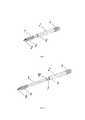
Фиг. 1 - винт, общий вид;FIG. 1 - screw, general view;
Фиг. 2 - винт, общий вид с разнесенными частями;FIG. 2 - screw, general view with separated parts;
Фиг. 3 - винт, вид в разрезе;FIG. 3 - screw, sectional view;
Фиг. 4 - винт (вид в разрезе) показан по месту установки в шейке бедренной кости;FIG. 4 - screw (view in section) is shown at the place of installation in the neck of the femur;
Фиг. 5 - три винта показаны по месту установки в шейке бедренной кости.FIG. 5 - three screws are shown at the place of installation in the femoral neck.
Осуществление полезной модели.Implementation of the utility model.
Винт состоит из двух частей дистального стержня 1 и проксимального стержня 2. Общая длина винта находится в диапазоне от 70 до 110 мм, диаметр стержней 1 и 2 (фиг. 1; 2; 3) не превышает 8 мм. Части 1 и 2 соединены телескопически, так что дистальный стержень 1 имеет возможность перемещаться вдоль проксимального стержня 2 из одного крайнего положения в другое крайнее положение на расстояние в диапазоне от 10 до 20 мм т.е. обеспечивается ход динамизации до 20 мм и возможность увеличения длины до 10 мм при необходимости. Проксимальный стержень 2 выполнен с продольным сквозным осевым каналом 3 (фиг. 2; 3), снабжен резьбовым участком 4 (фиг. 1; 2; 3), для обеспечения сцепления с костью в области вертела, и шестигранным углублением 5 (фиг. 3), под отвертку. Дистальный стержень 1 снабжен резьбовым участком 6 (фиг. 1; 2; 3), для обеспечения сцепления с костью в области части шейки с головкой, и шестигранным углублением 7 (фиг. 3), под отвертку. Резьбовой участок 6 выполнен на дистальном конце 8 (фиг. 1; 2; 3) дистального стрежня 1. Углубление под отвертку 7 выполнено на проксимальном конце дистального стержня 1. Резьбовой участок 4 и углубление под отвертку 6 выполнены на проксимальном конце проксимального стержня 2. Дистальный конец 8 дистального стержня 2 самосверлящий, содержит режущие кромки и самонарезающую винтовую нарезку на резьбовом участке 6. Проксимальный конец дистального стержня 1 установлен в сквозном осевом канале 3 проксимального стержня 2. Дистальный конец 9 (фиг. 1; 2; 3) проксимального стержня 2 завальцован, так что дистальный стержень 1 имеет возможность перемещаться вдоль проксимального стержня 2 из одного крайнего положения в другое крайнее положение, не выпадая. Проксимальном конец у дистального стержня 1 имеет чуть больший диаметр, чем его тело, выполнен буртик 10 (фиг. 2; 3), что обеспечивает его контакт с завальцованной частью проксимального стержня 2. Дистальный стержень 1 выполнен, длинной от 35 до 75 мм, в частности 50 мм из титанового сплава ВТ6 или из нержавеющей стали, в виде металлического стержня с диаметром тела от 4 до 5 мм, в частности 4,75 мм. Самонарезающая винтовая нарезка выполнена с шагом от 0,5 до 2,5 мм, в частности 1 мм. Шестигранное углубление под отвертку 7 размером 3,5 мм (допускается 3 и 3,3 мм). Шестигранное углубление под отвертку 5 размером 5 мм (допускается 4,5 и 5,5 мм). Проксимальный стержень 2 выполнен в виде канюлированного металлического стержня, с наружным диаметром тела 6,6 мм, из титанового сплава ВТ6 или из нержавеющей стали. Винтовая нарезка резьбового участка 4 выполнена с шагом от 0,5 до 1,5 мм, частности 0,5 мм. На проксимальном конце проксимальный стержень 2 содержит буртик образованный вальцовкой, препятствующий свободному выходу дистального стержня 1 из осевого канала 3. Винтовая нарезка резьбовых участков 4 и 6 предпочтительно выполнена с шагом от 0,5 до 2,5 мм, глубиной от 0,5 до 1,25 мм. Перемещение дистального стержня 1 в проксимальном стержне 2 обеспечивает возможность динамизации места перелома. Дистальный стержень 1 фиксируется в части шейки с головкой 11 (фиг. 4; 5). Проксимальный стрежень 2 фиксируется в области большого вертела 12 (фиг. 4; 5) позволяя дистальному стержню 1 динамизироваться, перемещаться относительно проксимального стержня 2. При динамизации происходит компрессия на стыке между частью шейки с головкой 11 и остальной частью бедренной кости во время ходьбы пациента, при этом запускается механизм механической стимуляции остеогенеза. Винты длиной от 70 до 80 мм имеют ход динамизации 10 мм. Винты длиной от 80 до 110 мм имеют ход динамизации 20 мм.The screw consists of two parts of the
Устройство позволяет зафиксировать шейку с головкой относительно остальной части бедренной кости и при ходьбе осуществлять динамическую компрессию на стыке отломков кости.The device allows you to fix the neck with the head relative to the rest of the femur and, when walking, to perform dynamic compression at the junction of bone fragments.
Использование полезной модели показано на примере остеосинтеза винтом длинной 90+10. Для введения винта используют бедренный навигатор (Устройство для лечения больных с травмами и последствиями травм проксимального отдела бедра, патенты RU 148219; RU 2535509; RU 120354.) После позиционирование бедренного навигатора, через направляющую втулку вскрывают кортикал и вводят винт в область перелома. Винт фиксируют на отвертке, рабочий конец которой устанавливается в углубления 5 и 7. При этом дистальный стержень 1 отодвигается вдоль осевого канала 3 проксимально стержня 2 на расстояние 10 мм и становится в нейтральное положение. В нейтральном положении длину винта можно увеличить на 10 мм подкручивая дистальный стержень отверткой. Разместив винт вдоль продольной оси шейки бедренной кости, при помощи отвертки винт резьбовым участком 6 вкручивают в часть шейки с головкой бедра, резьбовым участком 4 в области большого вертела. Проксимальный конец проксимального стержня 2 крепится в области большого вертела 12, что позволяет вводить винты минимальным доступом, без разрезов. При этом, так как поперечный размер винта мал (не более 8 мм в проксимальной части и не более 6,6 мм в дистальной части), одновременно в шейку можно ввести один, два или три винта (фиг. 5). Дистальный конец 8 дистального стержня 2 самосверлящий, содержит режущие кромки и самонарезающую винтовую нарезку, что позволяет вводить винт напрямую в кость, и не требует рассверливание канала под дистальный стержень 1, поэтому сохраняется массив кости и обеспечивается требуемая жесткость фиксации винта в головке. Для предотвращения вращения части шейки с головкой 11 относительно части с большим вертелом 12 может быть введено два или три винта (фиг. 5).The use of the utility model is shown by the example of osteosynthesis with a screw length of 90 + 10. For the insertion of a screw, a femoral navigator is used (Device for treating patients with injuries and consequences of injuries of the proximal femur, patents RU 148219; RU 2535509; RU 120354.) After positioning the femoral navigator, the cortical is opened through the guide sleeve and the screw is inserted into the fracture area. The screw is fixed on a screwdriver, the working end of which is installed in the
Claims (4)
Translated fromRussianPriority Applications (1)
| Application Number | Priority Date | Filing Date | Title |
|---|---|---|---|
| RU2018133910URU188428U1 (en) | 2018-09-25 | 2018-09-25 | SCREW FOR OSTEOSYNTHESIS OF THE FEMORAL NECK |
Applications Claiming Priority (1)
| Application Number | Priority Date | Filing Date | Title |
|---|---|---|---|
| RU2018133910URU188428U1 (en) | 2018-09-25 | 2018-09-25 | SCREW FOR OSTEOSYNTHESIS OF THE FEMORAL NECK |
Publications (1)
| Publication Number | Publication Date |
|---|---|
| RU188428U1true RU188428U1 (en) | 2019-04-11 |
Family
ID=66168691
Family Applications (1)
| Application Number | Title | Priority Date | Filing Date |
|---|---|---|---|
| RU2018133910URU188428U1 (en) | 2018-09-25 | 2018-09-25 | SCREW FOR OSTEOSYNTHESIS OF THE FEMORAL NECK |
Country Status (1)
| Country | Link |
|---|---|
| RU (1) | RU188428U1 (en) |
Cited By (2)
| Publication number | Priority date | Publication date | Assignee | Title |
|---|---|---|---|---|
| CN113893018A (en)* | 2021-09-16 | 2022-01-07 | 上海市第六人民医院 | Tension screw for femoral neck fracture and use method thereof |
| RU2835615C1 (en)* | 2024-07-31 | 2025-03-03 | федеральное государственное автономное образовательное учреждение высшего образования "Тюменский государственный университет" | Two-component osteosynthesis screw |
Citations (12)
| Publication number | Priority date | Publication date | Assignee | Title |
|---|---|---|---|---|
| US4940467A (en)* | 1988-02-03 | 1990-07-10 | Tronzo Raymond G | Variable length fixation device |
| RU8888U1 (en)* | 1998-06-26 | 1999-01-16 | Саратовский государственный медицинский университет | COMPRESSING SCREW |
| EP0617927B1 (en)* | 1993-03-28 | 1999-01-20 | Yehiel Gotfried | Surgical device for connection of fractured bones |
| JP2002360599A (en)* | 2001-06-05 | 2002-12-17 | Ikushi Yamada | Screw for bone coapatation having escape preventive function |
| WO2004069065A1 (en)* | 2003-02-10 | 2004-08-19 | Cell Center Cologne Gmbh | Dynamic epiphysial telescopic screw |
| RU2260398C1 (en)* | 2003-12-15 | 2005-09-20 | Девин Игорь Владимирович | Device for applying dynamic compression osteosynthesis of femur neck |
| US20080119855A1 (en)* | 2005-02-19 | 2008-05-22 | Aesculap Ag & Co. Kg | Orthopedic fixation system |
| US20100211112A1 (en)* | 2007-09-26 | 2010-08-19 | Zimmer, Gmbh | Bone anchoring device for the operative repair of fractures |
| US20130116694A1 (en)* | 2011-05-17 | 2013-05-09 | Silas Zurschmiede | Telescoping screw for femoral neck fractures |
| US20140214034A1 (en)* | 2013-01-25 | 2014-07-31 | Fady Rayes | Cannulated telescopic femoral neck screw device and related fixation method |
| US9028534B2 (en)* | 2001-10-18 | 2015-05-12 | Orthoip, Llc | Bone screw system and method |
| RU2621587C2 (en)* | 2015-05-19 | 2017-06-06 | Государственное бюджетное учреждение здравоохранения города Москвы Научно-исследовательский институт скорой помощи имени Н.В. Склифосовского Департамента здравоохранения г. Москвы | Device set for limb bone fractures osteosynthesis |
- 2018
- 2018-09-25RURU2018133910Upatent/RU188428U1/ennot_activeIP Right Cessation
Patent Citations (12)
| Publication number | Priority date | Publication date | Assignee | Title |
|---|---|---|---|---|
| US4940467A (en)* | 1988-02-03 | 1990-07-10 | Tronzo Raymond G | Variable length fixation device |
| EP0617927B1 (en)* | 1993-03-28 | 1999-01-20 | Yehiel Gotfried | Surgical device for connection of fractured bones |
| RU8888U1 (en)* | 1998-06-26 | 1999-01-16 | Саратовский государственный медицинский университет | COMPRESSING SCREW |
| JP2002360599A (en)* | 2001-06-05 | 2002-12-17 | Ikushi Yamada | Screw for bone coapatation having escape preventive function |
| US9028534B2 (en)* | 2001-10-18 | 2015-05-12 | Orthoip, Llc | Bone screw system and method |
| WO2004069065A1 (en)* | 2003-02-10 | 2004-08-19 | Cell Center Cologne Gmbh | Dynamic epiphysial telescopic screw |
| RU2260398C1 (en)* | 2003-12-15 | 2005-09-20 | Девин Игорь Владимирович | Device for applying dynamic compression osteosynthesis of femur neck |
| US20080119855A1 (en)* | 2005-02-19 | 2008-05-22 | Aesculap Ag & Co. Kg | Orthopedic fixation system |
| US20100211112A1 (en)* | 2007-09-26 | 2010-08-19 | Zimmer, Gmbh | Bone anchoring device for the operative repair of fractures |
| US20130116694A1 (en)* | 2011-05-17 | 2013-05-09 | Silas Zurschmiede | Telescoping screw for femoral neck fractures |
| US20140214034A1 (en)* | 2013-01-25 | 2014-07-31 | Fady Rayes | Cannulated telescopic femoral neck screw device and related fixation method |
| RU2621587C2 (en)* | 2015-05-19 | 2017-06-06 | Государственное бюджетное учреждение здравоохранения города Москвы Научно-исследовательский институт скорой помощи имени Н.В. Склифосовского Департамента здравоохранения г. Москвы | Device set for limb bone fractures osteosynthesis |
Cited By (3)
| Publication number | Priority date | Publication date | Assignee | Title |
|---|---|---|---|---|
| CN113893018A (en)* | 2021-09-16 | 2022-01-07 | 上海市第六人民医院 | Tension screw for femoral neck fracture and use method thereof |
| RU2835615C1 (en)* | 2024-07-31 | 2025-03-03 | федеральное государственное автономное образовательное учреждение высшего образования "Тюменский государственный университет" | Two-component osteosynthesis screw |
| RU233537U1 (en)* | 2025-01-17 | 2025-04-24 | Федеральное государственное бюджетное образовательное учреждение высшего образования "Казанский Государственный медицинский университет" Министерства здравоохранения Российской Федерации | Anchor retainer |
Similar Documents
| Publication | Publication Date | Title |
|---|---|---|
| EP1656899B1 (en) | Glenoid instrumentation anti-migration threaded fastener | |
| US6524313B1 (en) | Intramedullary nail system | |
| US10729482B2 (en) | Bone fixation device | |
| EP2916742B1 (en) | Dynamic axial nail for intramedullary treatment of long bone fractures | |
| US8876822B2 (en) | Intramedullary nail system with tang fixation after lock screw placement | |
| RU2585732C2 (en) | Implantable device for preventive or treatment therapy of femoral fractures, corresponding auxiliary means | |
| US3783860A (en) | Intramedullary rod | |
| CA3082699C (en) | Cannulated orthopedic screw and method of reducing a fracture of the lateral malleolus | |
| US10251683B2 (en) | Intramedullary nail | |
| RU188428U1 (en) | SCREW FOR OSTEOSYNTHESIS OF THE FEMORAL NECK | |
| CN107223040B (en) | Intramedullary fixation device and system for use in hip and femur fracture surgery | |
| US9655661B1 (en) | Cannulated orthopedic screw and method of reducing and fixing a fracture of the lateral malleolus | |
| RU2322209C1 (en) | Method and compression device for making femur neck osteosynthesis | |
| CN206792478U (en) | Bone cement screw | |
| CN108348284B (en) | Intraosseous screw assembly and internal fixation system comprising same | |
| CN105011998A (en) | Wing-shaped intramedullary nail | |
| RU2706140C1 (en) | Cannulated screw for minimally invasive osteosynthesis of unstable pelvic ring injuries | |
| RU155662U1 (en) | COMPRESSING SCREW | |
| RU2076657C1 (en) | Device for fixation of fragments of femur proximal section at treatment of diseases connected with rotation osteotomy | |
| RU62796U1 (en) | LOCK FOR INTRACOSTIC LOCKING OSTEOSYNTHESIS | |
| RU149731U1 (en) | SCREW FOR OSTESYNTHESIS OF THE PELVIS | |
| RU202086U1 (en) | Anchoring screw for osteosynthesis | |
| RU130831U1 (en) | DEVICE FOR TREATING ANKELIC FRACTURES WITH REMOVAL OF THE DISTAL TIBEROSY SYNDESMOSIS | |
| RU2164390C2 (en) | Method for reducing distal intertibial syndesmosis and removing external foot subluxation | |
| USRE28502E (en) | Intramedullary rod |
Legal Events
| Date | Code | Title | Description |
|---|---|---|---|
| MM9K | Utility model has become invalid (non-payment of fees) | Effective date:20190412 |