RU177536U1 - DIGITAL X-RAY FLUOROGRAPHIC CAMERA - Google Patents
DIGITAL X-RAY FLUOROGRAPHIC CAMERADownload PDFInfo
- Publication number
- RU177536U1 RU177536U1RU2017124942URU2017124942URU177536U1RU 177536 U1RU177536 U1RU 177536U1RU 2017124942 URU2017124942 URU 2017124942URU 2017124942 URU2017124942 URU 2017124942URU 177536 U1RU177536 U1RU 177536U1
- Authority
- RU
- Russia
- Prior art keywords
- digital
- processing unit
- image
- ray
- comparator
- Prior art date
Links
- 238000012360testing methodMethods0.000claimsabstractdescription33
- 238000012545processingMethods0.000claimsabstractdescription21
- 239000011159matrix materialSubstances0.000claimsabstractdescription13
- 230000001681protective effectEffects0.000claimsabstractdescription11
- 239000000463materialSubstances0.000claimsabstractdescription10
- 230000007170pathologyEffects0.000claimsabstractdescription10
- 238000010586diagramMethods0.000claimsabstractdescription4
- 230000005855radiationEffects0.000claimsabstractdescription4
- 201000010099diseaseDiseases0.000abstractdescription6
- 208000037265diseases, disorders, signs and symptomsDiseases0.000abstractdescription6
- 238000012216screeningMethods0.000abstractdescription4
- 210000000115thoracic cavityAnatomy0.000abstractdescription4
- 210000004072lungAnatomy0.000description4
- 230000002685pulmonary effectEffects0.000description4
- 238000005259measurementMethods0.000description3
- 238000010835comparative analysisMethods0.000description2
- 238000013461designMethods0.000description2
- 238000001514detection methodMethods0.000description2
- 238000003745diagnosisMethods0.000description2
- XAGFODPZIPBFFR-UHFFFAOYSA-NaluminiumChemical compound[Al]XAGFODPZIPBFFR-UHFFFAOYSA-N0.000description1
- 229910052782aluminiumInorganic materials0.000description1
- 229940079593drugDrugs0.000description1
- 239000003814drugSubstances0.000description1
- 231100000915pathological changeToxicity0.000description1
- 230000036285pathological changeEffects0.000description1
- 208000008128pulmonary tuberculosisDiseases0.000description1
- 201000008827tuberculosisDiseases0.000description1
Images

Classifications
- A—HUMAN NECESSITIES
- A61—MEDICAL OR VETERINARY SCIENCE; HYGIENE
- A61B—DIAGNOSIS; SURGERY; IDENTIFICATION
- A61B6/00—Apparatus or devices for radiation diagnosis; Apparatus or devices for radiation diagnosis combined with radiation therapy equipment
Landscapes
- Health & Medical Sciences (AREA)
- Life Sciences & Earth Sciences (AREA)
- Medical Informatics (AREA)
- Engineering & Computer Science (AREA)
- Radiology & Medical Imaging (AREA)
- Biomedical Technology (AREA)
- Biophysics (AREA)
- Nuclear Medicine, Radiotherapy & Molecular Imaging (AREA)
- Optics & Photonics (AREA)
- Pathology (AREA)
- Physics & Mathematics (AREA)
- High Energy & Nuclear Physics (AREA)
- Heart & Thoracic Surgery (AREA)
- Molecular Biology (AREA)
- Surgery (AREA)
- Animal Behavior & Ethology (AREA)
- General Health & Medical Sciences (AREA)
- Public Health (AREA)
- Veterinary Medicine (AREA)
- Apparatus For Radiation Diagnosis (AREA)
Abstract
Translated fromRussianDescription
Translated fromRussianПредлагаемое техническое решение относится к области медицинской техники, точнее к рентгеновским флюорографам, используемым для скрининг-диагностики заболеваний органов грудной полости.The proposed technical solution relates to the field of medical technology, more specifically to x-ray fluorographs used for screening diagnosis of diseases of the chest cavity.
Известна цифровая рентгенофлюорографическая камера, в которой в качестве фотодетектора используется запоминающий экран, нанесенный на поверхность барабана. После экспозиции считывание скрытого изображения производится с помощью инфракрасного лазера (Авторское свидетельство №1018623, от 13.10.82, А61В 6/00) [1].A digital X-ray fluorography camera is known in which a memory screen deposited on a drum surface is used as a photodetector. After exposure, the reading of the latent image is carried out using an infrared laser (Copyright certificate No. 1018623, dated 13.10.82, АВВ 6/00) [1].
Применение фотодетектора с запоминающим экраном [1] позволяет на порядок снизить лучевую нагрузку на пациента (по сравнению с пленочным флюорографом). Однако данная технология получения флюорографического снимка чрезвычайно дорога. В нашей стране фото детекторы с запоминающим экраном не выпускаются и в практике фтизиопульмонологии не применяются.The use of a photodetector with a storage screen [1] allows one to reduce the radiation load on the patient by an order of magnitude (compared with a film fluorograph). However, this X-ray technology is extremely expensive. In our country, photo detectors with a storage screen are not available and are not used in the practice of phthisiopulmonology.
Известна также цифровая рентгенофлюорографическая камера, содержащая фоторегистратор, включающий флюоресцирующий экран и сверхсветосильный объектив с ПЗС-матрицей, закрепленный в светонепроницаемом корпусе, защищенным свинцом, с входным окном, закрытым защитным экраном из рентгенопрозрачного и светонепроницаемого материала, к которому примыкает флюоресцирующий экран (Основы рентгенодиагностической техники. - Под редакцией Н.Н. Блинова. - М.: Медицина, 2002. - С. 192) [2]. Цифровая рентгенофлюорографическая камера [2] входит в состав легочного флюорографа, например «Ренекс-Флюоро», выпускаемого отечественной фирмой «Гелпик».A digital X-ray fluorography camera is also known, comprising a photographic recorder including a fluorescent screen and an ultra-fast lens with a CCD matrix, mounted in a light-tight housing protected by lead, with an input window, a closed protective screen made of X-ray transparent and light-tight material, to which the fluorescent screen adjoins ( . - Edited by NN Blinov. - M .: Medicine, 2002. - S. 192) [2]. A digital X-ray fluorography camera [2] is part of a pulmonary fluorograph, for example, Renex-Fluoro, manufactured by the domestic company Gelpik.
Средняя эффективная доза, получаемая пациентом на камере [2] составляет 50 мкЗв. Эта доза значительно ниже, чем на пленочной камере, что позволяет широко использовать цифровую камеру [2] для скрининг-диагностики заболеваний органов грудной полости.The average effective dose received by the patient on the camera [2] is 50 μSv. This dose is much lower than on a film camera, which makes it possible to widely use a digital camera [2] for screening diagnostics of diseases of the chest cavity.
Недостатком цифровой рентгенофлюорографической камеры [2], как и всех известных аналогов является отсутствие в ее конструкции аналитической системы, обеспечивающей машинную диагностику цифрового изображения в режиме норма - патология. Дело в том, что при скрининг-диагностике заболеваний органов грудной полости, проводимой например с целью выявления туберкулеза легких на ранней стадии развития болезни, врачу-рентгенологу за рабочую смену приходится просматривать большое число изображений (до 250). По причине утомления зрения, особенно в конце смены, происходит просмотр патологии. Согласно статистики, это происходит в 30% случаях, что конечно не допустимо при таком грозном заболевании как туберкулез.The disadvantage of a digital X-ray fluorography camera [2], as well as of all known analogues, is the absence in its design of an analytical system that provides machine diagnostics of digital images in the norm - pathology mode. The fact is that when screening for the diagnosis of diseases of the chest cavity, carried out for example to detect pulmonary tuberculosis at an early stage of the disease, the radiologist has to view a large number of images (up to 250) for a shift. Due to fatigue of vision, especially at the end of the shift, a pathology is viewed. According to statistics, this happens in 30% of cases, which of course is not permissible with such a formidable disease as tuberculosis.
Наиболее близкой по конструкции к заявляемому объекту является цифровая флюорографическая камера, содержащая светонепроницаемый корпус, защищенный свинцом, с входным окном, закрытым защитным экраном из рентгенопрозрачного и светонепроницаемого материала, к которому со стороны камеры примыкает флюоресцирующий экран плоской формы, оптически сопряженный посредством светосильного объектива с фоторегистратором цифрового типа, соединенным с блоком обработки электрического сигнала, включающего усилитель сигнала, аналого-цифровой преобразователь, схему формирования цифровой матрицы изображения, подключенную через схему воспроизведения к видеомонитору, а также, блок обработки электрического сигнала содержит цифровой архив тестовых снимков, и компаратор, имеющий два входа, один из которых подключен через коммутатор к архиву тестовых снимков, а другой - к цифровой матрице текущего изображения, а выход компаратора соединен с анализатором результирующего сигнала, снабженным индикатором «Норма - патология», при этом блок обработки электрического сигнала подключен к пульту управления (Патент на полезную модель №117792 от 08.02.2012 [3].The closest in design to the claimed object is a digital fluorographic camera containing a light-tight housing, protected by lead, with an input window, a closed protective screen made of X-ray transparent and opaque material, to which on the side of the camera there is a flat-shaped fluorescent screen optically coupled by means of a fast lens with a photographic recorder digital type connected to an electric signal processing unit including a signal amplifier, analog-to-digital converter a developer, a digital image matrix generation circuit connected via a playback circuit to a video monitor, and an electric signal processing unit contains a digital archive of test images, and a comparator having two inputs, one of which is connected through a switch to an archive of test images, and the other to digital matrix of the current image, and the output of the comparator is connected to the analyzer of the resulting signal, equipped with the indicator "Normal - pathology", while the processing unit of the electrical signal is connected to the remote in management (Utility Model Patent No. 1177792 dated 02/08/2012 [3].
Аналог [3] был выбран нами в качестве прототипа.The analogue [3] was chosen by us as a prototype.
Цифровая камера [3] значительно облегчает работу рентгенолога, так как позволяет в автоматическом режиме выявлять на рентгеновском снимке возможную легочную патологию.A digital camera [3] greatly facilitates the work of a radiologist, as it allows the automatic detection of possible pulmonary pathology on an x-ray.
Недостаток прототипа [3] выражается в низкой точности выявления патологии. Одной из причин тому является отсутствии в цифровой камере [3] элементов юстировки компаратора, в котором производится сравнение текущего рентгеновского изображения с тестовым снимком. Дело в том, что при сравнительном анализе этих снимков они должны совпадать как по масштабу, так и по положению. Добиться этого можно путем юстировки компаратора. Отсутствие такой возможности в прототипе снижает точность работы цифровой камеры [3].The disadvantage of the prototype [3] is expressed in the low accuracy of detection of pathology. One of the reasons for this is the absence of a comparator adjustment element in the digital camera [3], in which the current X-ray image is compared with the test image. The fact is that in a comparative analysis of these images, they must coincide both in scale and in position. This can be achieved by adjusting the comparator. The lack of such a possibility in the prototype reduces the accuracy of the digital camera [3].
Целью настоящей работы является оснащение цифровой рентгеновской камеры элементами юстировки компаратора.The aim of this work is to equip the digital X-ray camera with adjustment elements of the comparator.
Технический результат полезной модели выражается в расширении технических средств машинной рентгенодиагностики. Он достигается тем, что в цифровой рентгенофлюорографической камере, содержащей светонепроницаемый корпус, защищенный свинцом, с входным окном, закрытым защитным экраном из рентгенопрозрачного и светонепроницаемого материала, к которому с внутренней стороны камеры примыкает флюоресцирующий экран плоской формы, оптически сопряженный посредством светосильного объектива с фоторегистратором цифрового типа, соединенным с блоком обработки электрического сигнала, включающего усилитель сигнала, аналого-цифровой преобразователь, схему формирования цифровой матрицы изображения, подключенную через схему воспроизведения к видеомонитору, а также, блок обработки электрического сигнала с цифровым архивом тестовых снимков, и компаратором, имеющим два входа, один из которых подключен через коммутатор к архиву тестовых снимков, а другой - к цифровой матрице текущего изображения, а выход компаратора соединен с анализатором результирующего сигнала, снабженным индикатором «Норма - патология», при этом блок обработки электрического сигнала подключен к пульту управления, на внешней поверхности защитного экрана, по его углам, на расстоянии 20-25 мм от ближайших границ рабочего поля облучения закреплены координатные метки, выполненные из рентгеноконтрастного материала, а блок обработки электрического сигнала дополнен электрической схемой масштабирования тестового снимка и схемой перемещения тестового снимка относительно текущего изображения в двух взаимно перпендикулярных направлениях.The technical result of the utility model is expressed in the expansion of technical means of machine X-ray diagnostics. It is achieved by the fact that in a digital X-ray fluorography camera containing a light-tight housing protected by lead with an entrance window closed by a protective screen made of X-ray transparent and light-tight material, to which a flat-shaped fluorescent screen adjoins from the inside of the camera and is optically coupled by means of a fast lens with a digital photorecorder type connected to the electric signal processing unit, including a signal amplifier, analog-to-digital converter, pho circuit a digital image matrix, connected via a playback circuit to a video monitor, as well as an electric signal processing unit with a digital archive of test images, and a comparator with two inputs, one of which is connected through a switch to an archive of test images, and the other to a digital matrix of the current image, and the output of the comparator is connected to the analyzer of the resulting signal, equipped with an indicator "Normal - pathology", while the processing unit of the electrical signal is connected to the control panel, externally the surface of the protective screen, at its corners, at a distance of 20-25 mm from the nearest borders of the working radiation field, coordinate marks made of radiopaque material are fixed, and the electrical signal processing unit is supplemented by an electrical scaling diagram of the test image and the scheme of moving the test image relative to the current image in two mutually perpendicular directions.
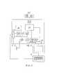
Далее описание сопровождается рисунками и пояснениями к ним. На фиг. 1 приведена блок-схема цифровой рентгенофлюорографической камеры, на фиг. 2 показано расположение координатных меток на защитном экране, а на фиг. 3 представлены основные элементы блока обработки электрического сигнала.Further description is accompanied by drawings and explanations to them. In FIG. 1 is a block diagram of a digital X-ray fluorography camera; FIG. 2 shows the location of the coordinate marks on the protective screen, and FIG. 3 shows the basic elements of an electric signal processing unit.
Цифровая рентгенофлюорографическая камера содержит светонепроницаемый корпус 1, защищенный свинцом, с входным окном, закрытым защитным экраном 2 из рентгенопрозрачного и светонепроницаемого материала, например алюминия, к которому с внутренней стороны камеры примыкает флюоресцирующий экран 3 плоской формы, оптически сопряженный посредством светосильного объектива 4 с фоторегистратором 5 цифрового типа (ПЗС-матрицей), соединенным с блоком обработки электрического сигнала 6. Блок обработки электрического сигнала 6 подключен к пульту управления 7, выполненному в виде клавиатуры к микропроцессору, расположенному в корпусе пульта управления 7. К пульту управления 7 подключен также видеомонитор 8, соединенный с блоком обработки электрического сигнала 6 и рентгеновский генератор 9, соединенный с рентгеновским излучателем 10.The digital X-ray fluorography camera contains a light-
На внешней поверхности защитного экрана 2, по его углам, на расстоянии 20-25 мм от ближайших границ рабочего поля облучения 11 закреплены координатные метки 12А, 12В, 12С, 12D, выполненные из рентгеноконтрастного материала, например свинца, имеющие, например, форму кольца, выполненного, например, из проволоки диаметром 1-1,5 мм, с центральным шариком диаметром 2-2,5 мм (фиг. 2).On the outer surface of the
Блок обработки электрического сигнала 6 содержит усилитель сигнала 13, приходящего с цифрового фоторегистратора 5 (фиг. 3), аналого-цифровой преобразователь 14, схему формирования цифровой матрицы изображения 151, подключенную через схему воспроизведения 16 и коммутатор 17, переключаемый клавиатурой пульта управления 7 к видеомонитору 8. Ячейка 152 предназначена для хранения цифровых рентгеновских снимков, выполненных за рабочую смену и подлежащих анализу. Выбор того или иного снимка осуществляется рентгенологом с помощью клавиатуры пульта управления 7. В состав блока обработки электрического сигнала 6 входит также архив тестовых снимков 18 и компаратор 19, имеющий два входа, один из которых подключен к архиву тестовых снимков 18. Это подключение осуществлено через переключатель 20, электрическую схему масштабирования цифрового изображения 21 и электрическую схему 22 перемещения тестового снимка в двух взаимно перпендикулярных направлениях. Переключатель 20 и электрические схемы 21, 22 соединены через коммутатор 23 с пультом управления 7 и управляются его клавиатурой. Второй вход компаратора 19 подключен к схеме формирования цифровой матрицы изображения 151. Выход компаратора 19 соединен с анализатором результирующего сигнала 24, снабженным индикатором 25 «Норма (n) - патология (p)».The electric
Предложенная цифровая рентгенофлюорографическая камера предназначена для работы в составе цифрового легочного флюорографа, например «Ренекс-Флюоро» фирмы «Гелпик». Ее работа основана на компарировании - сравнении изображений текущего и тестового снимков. При сравнительном анализе этих снимков они должны совпадать как по масштабу, так и по положению. Добиться этого можно путем юстировки компаратора. Отметим, что все тестовые снимки должны быть выполнены на том же цифровом легочном флюорографе, оснащенным цифровой камерой с координатными метками 12А, 12В, 12С, 12D. Все тестовые снимки хранятся в цифровом виде в архиве 18.The proposed digital X-ray fluorography camera is designed to work as part of a digital pulmonary fluorograph, for example, Renex-Fluoro company Gelpik. Her work is based on comparing - comparing the images of the current and test images. In a comparative analysis of these images, they should coincide both in scale and in position. This can be achieved by adjusting the comparator. Note that all test images should be performed on the same digital pulmonary fluorograph equipped with a digital camera with
Юстировка компаратора 19 производится следующим образом. Вначале на цифровом флюорографе выполняется снимок без пациента, на котором изображаются координатные метки 12А, 12В, 12С, 12D. Цифровое изображение этих координатных меток из ячейки 151 вводится в компаратор 19 и изображается на экране видеомонитора 8. Далее из архива 18 в компаратор 19 вводится любой из тестовых снимков (все тестовые снимки, хранящиеся в архиве 18, геометрически сопряжены между собой). Изображение тестового снимка, введенного в компаратор 19, также выводится на видеомонитор 8. После этого рентгенолог с помощью клавиатуры пульта управления 7 производит перемещение на видеомониторе 8 тестового снимка (при необходимости изменяя его масштаб) до совпадения изображения его координатных меток 12А, 12В, 12С, 12D с изображением координатных меток текущего снимка, введенного в компаратор из ячейки 151. После этой операции в компараторе 19 текущий и тестовый снимки будут совпадать между собой как по масштабу, так и по положению. Юстировку компаратора 19 необходимо проводить не реже одного раза в месяц.Adjustment of the
Цифровая рентгенофлюорографическая камера в практической работе используется следующим образом. После выполнения флюорографии текущее изображение легких выводится на экран видеомонитора 8 для его предварительного просмотра. При отсутствии на нем явных патологических изменений рентгенолог переходит ко второму этапу анализа. Для этого с помощью клавиатуры пульта управления 7 рентгенолог вводит в микропроцессор данные (возраст, пол пациента, его телосложение, режимы флюорографии), необходимые для выбора тестового изображения. Тестовое изображение легких, характеризующее норму, хранится в архиве тестовых снимков 18 и используется как эталонное. Далее рентгенолог задает расположение и размеры участка измерения, например верхняя доля правого легкого, диаметр участка измерения 40 мм. После этого по команде с пульта управления 7 этот участок тестового снимка через переключатель 20 вводится в левый вход компаратора 19, а в правый вход компаратора 19 вводится аналогичный участок текущего изображения; он поступает из цифровой матрицы 151. В компараторе 19 сравниваются относительные значения яркостей выбранных участков тестового и текущего цифровых изображений (относительное значение яркости определяется как разность яркостей целевого участка и чистого, незатененного телом пациента). Анализатор 24 результирующего сигнала определяет отклонение по яркости измеряемого участка текущего изображения от тестового. При отклонении относительной яркости текущего изображения от тестового до 3% текущее изображение считается в норме и на индикаторе 25 загорается буква n. Если результат измерения превышает это значение (более 3%), то на индикаторе 25 появляется буква p (означающая возможную патологию). В этом случае рентгенолог приступает к более тщательному анализу текущего изображения легких.Digital X-ray fluorography camera in practical work is used as follows. After performing fluorography, the current image of the lungs is displayed on the screen of the
Claims (1)
Translated fromRussianPriority Applications (1)
| Application Number | Priority Date | Filing Date | Title |
|---|---|---|---|
| RU2017124942URU177536U1 (en) | 2017-07-13 | 2017-07-13 | DIGITAL X-RAY FLUOROGRAPHIC CAMERA |
Applications Claiming Priority (1)
| Application Number | Priority Date | Filing Date | Title |
|---|---|---|---|
| RU2017124942URU177536U1 (en) | 2017-07-13 | 2017-07-13 | DIGITAL X-RAY FLUOROGRAPHIC CAMERA |
Publications (1)
| Publication Number | Publication Date |
|---|---|
| RU177536U1true RU177536U1 (en) | 2018-02-28 |
Family
ID=61568029
Family Applications (1)
| Application Number | Title | Priority Date | Filing Date |
|---|---|---|---|
| RU2017124942URU177536U1 (en) | 2017-07-13 | 2017-07-13 | DIGITAL X-RAY FLUOROGRAPHIC CAMERA |
Country Status (1)
| Country | Link |
|---|---|
| RU (1) | RU177536U1 (en) |
Cited By (1)
| Publication number | Priority date | Publication date | Assignee | Title |
|---|---|---|---|---|
| RU2721662C1 (en)* | 2019-07-01 | 2020-05-21 | Акционерное общество "ИНСТИТУТ ПРИКЛАДНОЙ ФИЗИКИ" | Digital x-ray receiver |
Citations (2)
| Publication number | Priority date | Publication date | Assignee | Title |
|---|---|---|---|---|
| SU1018623A1 (en)* | 1982-10-13 | 1983-05-23 | Московский научно-исследовательский институт туберкулеза | X-ray diagnostics apparatus |
| RU117792U1 (en)* | 2012-02-08 | 2012-07-10 | Общество с ограниченной ответственностью Совместное русско-французское предприятие "СпектрАп" | DIGITAL X-RAY FLUOROGRAPHIC CAMERA |
- 2017
- 2017-07-13RURU2017124942Upatent/RU177536U1/enactive
Patent Citations (2)
| Publication number | Priority date | Publication date | Assignee | Title |
|---|---|---|---|---|
| SU1018623A1 (en)* | 1982-10-13 | 1983-05-23 | Московский научно-исследовательский институт туберкулеза | X-ray diagnostics apparatus |
| RU117792U1 (en)* | 2012-02-08 | 2012-07-10 | Общество с ограниченной ответственностью Совместное русско-французское предприятие "СпектрАп" | DIGITAL X-RAY FLUOROGRAPHIC CAMERA |
Non-Patent Citations (1)
| Title |
|---|
| ОСНОВЫ РЕНТГЕНОДИАГНОСТИЧЕСКОЙ ТЕХНИКИ, 2002.* |
Cited By (1)
| Publication number | Priority date | Publication date | Assignee | Title |
|---|---|---|---|---|
| RU2721662C1 (en)* | 2019-07-01 | 2020-05-21 | Акционерное общество "ИНСТИТУТ ПРИКЛАДНОЙ ФИЗИКИ" | Digital x-ray receiver |
Similar Documents
| Publication | Publication Date | Title |
|---|---|---|
| JP2001351091A (en) | Image processing apparatus, photographing apparatus, image processing system, image processing method, and storage medium | |
| JP7397636B2 (en) | Radiographic imaging system, method and program | |
| JP3832173B2 (en) | Medical image reading device | |
| US10568601B2 (en) | Radiography system and method of controlling radiography system thereof | |
| US12226251B2 (en) | Imaging support device, and operation method and operation program for the same | |
| JP2006141904A (en) | Radiographic apparatus | |
| US20230016072A1 (en) | Imaging support device, operation method for the same and operation program | |
| RU177536U1 (en) | DIGITAL X-RAY FLUOROGRAPHIC CAMERA | |
| CN115460984A (en) | Photographing support device, method and program for operating the same | |
| JP7397635B2 (en) | Radiation detection device, radiation detection system, control method and program | |
| EP1525849B1 (en) | Fluoroscopic apparatus and method | |
| KR101577563B1 (en) | X-ray Detector Module with Medical Diagnostic Ruler. | |
| JP2009183562A (en) | Radiation imaging system | |
| US20070036419A1 (en) | System and method for interactive definition of image field of view in digital radiography | |
| RU117792U1 (en) | DIGITAL X-RAY FLUOROGRAPHIC CAMERA | |
| US11944479B2 (en) | Medical image diagnosis apparatus, x-ray computed tomography apparatus, and medical image diagnosis assisting method | |
| JP7271999B2 (en) | Image processing device, radiography system, program | |
| JP4876955B2 (en) | Display control apparatus and PET / CT apparatus | |
| JP7453345B2 (en) | Photography support device, its operating method, and operating program | |
| JP7348361B2 (en) | Image processing device | |
| JP2006255216A (en) | X-ray diagnostic imaging apparatus | |
| JPH0531747B2 (en) | ||
| JP2001292992A (en) | Radiography equipment | |
| JP2004337197A (en) | X-ray imaging equipment | |
| WO2025216256A1 (en) | Imaging device, radiation imaging device, control method thereof, and program |