RU163628U1 - TRANSPEDICULAR POLIAXIAL SCREW - Google Patents
TRANSPEDICULAR POLIAXIAL SCREWDownload PDFInfo
- Publication number
- RU163628U1 RU163628U1RU2016103447/14URU2016103447URU163628U1RU 163628 U1RU163628 U1RU 163628U1RU 2016103447/14 URU2016103447/14 URU 2016103447/14URU 2016103447 URU2016103447 URU 2016103447URU 163628 U1RU163628 U1RU 163628U1
- Authority
- RU
- Russia
- Prior art keywords
- screw
- screw shaft
- head
- thread
- shaft
- Prior art date
Links
- 230000008719thickeningEffects0.000claimsabstractdescription33
- 230000007423decreaseEffects0.000claimsabstractdescription15
- 230000015572biosynthetic processEffects0.000claimsabstractdescription12
- 230000007704transitionEffects0.000claimsabstractdescription6
- 210000000988bone and boneAnatomy0.000description12
- 238000009434installationMethods0.000description6
- 241000826860TrapeziumSpecies0.000description2
- 230000006378damageEffects0.000description2
- 201000010099diseaseDiseases0.000description2
- 208000037265diseases, disorders, signs and symptomsDiseases0.000description2
- 230000003313weakening effectEffects0.000description2
- 229910001069Ti alloyInorganic materials0.000description1
- 238000002048anodisation reactionMethods0.000description1
- 230000021615conjugationEffects0.000description1
- 239000003814drugSubstances0.000description1
- 229910052500inorganic mineralInorganic materials0.000description1
- 238000003780insertionMethods0.000description1
- 230000037431insertionEffects0.000description1
- 239000011707mineralSubstances0.000description1
- 230000000399orthopedic effectEffects0.000description1
- 230000002269spontaneous effectEffects0.000description1
Images


Landscapes
- Surgical Instruments (AREA)
Abstract
Translated fromRussianDescription
Translated fromRussianПолезная модель относится к медицине и может быть использована в нейрохирургии, ортопедии, травматологии, вертебрологии, в частности, в области создания систем коррекции и фиксации позвоночника.The utility model relates to medicine and can be used in neurosurgery, orthopedics, traumatology, vertebrology, in particular, in the field of creating systems for correction and fixation of the spine.
Известен транспедикулярный полиаксиальный винт, представляющий собой стержень винта и головку. Стержень винта выполнен на одном конце с резьбой на рабочей части, а на другом конце со сферическим утолщением, которое установлено в головку. Стержень винта имеет возможность поворота относительно головки. Головка выполнена со сквозным отверстием, имеющим в верхней части внутреннюю упорную резьбу для установки в верхнюю часть головки блокирующего винта, и с пазом для установки в него продольного стержня (патент США 6488681, А61В 17/70 от 01.05.2001).Known transpedicular polyaxial screw, which is a screw shaft and a head. The screw rod is made at one end with a thread on the working part, and at the other end with a spherical thickening, which is installed in the head. The screw shaft is rotatable relative to the head. The head is made with a through hole having an internal stop thread in the upper part for installation in the upper part of the head of the locking screw, and with a groove for installing a longitudinal shaft in it (US patent 6488681, АВВ 17/70 dated 05/01/2001).
Недостатком данного устройства является возможность ослабления продольного стержня, а, следовательно, неудовлетворительная стабильность фиксации поврежденного сегмента позвоночника.The disadvantage of this device is the possibility of weakening the longitudinal rod, and, therefore, unsatisfactory stability of fixation of the damaged segment of the spine.
Наиболее близким по технической сущности к заявляемому (устройству) является устройство транспедикулярного полиаксиального винта, содержащее винт (стержень винта), головку, вставку, гайку-блокиратор (блокирующий винт). Винт (стержень винта) имеет рабочую часть с резьбой на одном конце и сферическое утолщение на другом конце и установлен в головку, имеющую сквозное отверстие с внутренней прямоугольной упорной резьбой и паз с шириной, позволяющей установить в него продольный стержень. Винт (стержень винта) имеет возможность поворота относительно головки с общим углом отклонения в радиальном положении до 55 градусов, а в его сферическом утолщении содержится элемент, позволяющий создать крутящий момент относительно оси стержня винта. В головку установлена вставка, препятствующая выпадению винта (стержня винта) из головки и имеющая с одной стороны сферическую поверхность, соответствующую сферическому утолщению винта (стержня винта), с другой стороны - паз с возможностью установки в него продольного стержня, а со сторон, соприкасающихся с внутренней частью головки два оппозитно расположенных глухих отверстия, причем на одной оси с этими отверстиями в головке расположены другие два глухих отверстия. Гайка-блокиратор (блокирующий винт) содержит наружную прямоугольную упорную резьбу, соответствующую внутренней резьбе на головке и элемент, позволяющий приложить крутящий момент для вворачивания гайки-блокиратора (блокирующего винта) в головку. На торце гайки-блокиратора (блокирующего винта), который может соприкасаться с продольным стержнем, выполнено кольцевое ребро, профиль резьбы рабочей части винта (стержня винта) переменный и представляет собой неравнобедренную трапецию, причем основания трапеции уменьшаются от сферического утолщения к его кончику, при этом наружный диаметр рабочей части винта (стержня винта) постоянен, а внутренний - уменьшается от сферического утолщения к кончику. На головке выполнена кольцевая трапецеидальная проточка (патент РФ на полезную модель 154118, А61В 17/70 от 13.11.2014, опубликовано: 20.08.2015).Closest to the technical nature of the claimed (device) is a transpedicular polyaxial screw device containing a screw (screw shaft), head, insert, lock nut (locking screw). The screw (screw shaft) has a working part with a thread on one end and a spherical thickening on the other end and is installed in the head, having a through hole with an internal rectangular thrust thread and a groove with a width that allows you to install a longitudinal shaft in it. The screw (screw shaft) has the ability to rotate relative to the head with a total deflection angle in the radial position of up to 55 degrees, and in its spherical bulge contains an element that allows you to create torque relative to the axis of the screw shaft. An insert is installed in the head to prevent the screw (screw shaft) from falling out of the head and having on one side a spherical surface corresponding to a spherical thickening of the screw (screw shaft), on the other hand, a groove with the possibility of installing a longitudinal shaft, and from the sides in contact with the inner part of the head is two opposed blind holes, with the other two blind holes located on the same axis as these holes in the head. The locking nut (locking screw) contains an external rectangular thrust thread corresponding to the internal thread on the head and an element that allows you to apply torque to screw the locking nut (locking screw) into the head. At the end of the locking nut (locking screw), which can be in contact with the longitudinal shaft, an annular rib is made, the thread profile of the working part of the screw (screw shaft) is variable and is an isosceles trapezium, and the trapezium bases decrease from a spherical thickening to its tip, while the outer diameter of the working part of the screw (screw shaft) is constant, and the inner diameter decreases from a spherical thickening to the tip. An annular trapezoidal groove is made on the head (RF patent for utility model 154118, АВВ 17/70 dated 11/13/2014, published: 08/20/2015).
Недостатком данного устройства является большое количество деталей, возможность ослабления продольного стержня, а, следовательно, неудовлетворительная стабильность фиксации поврежденного сегмента позвоночника.The disadvantage of this device is the large number of parts, the possibility of weakening the longitudinal rod, and, therefore, the poor stability of fixation of the damaged segment of the spine.
Задачей полезной модели является разработка транспедикулярного полиаксиального винта простой конструкции для стабильной фиксации поврежденного сегмента позвоночника.The objective of the utility model is to develop a transpedicular polyaxial screw of simple design for stable fixation of the damaged segment of the spine.
Технический результат полезной модели заключается в обеспечении стабильной фиксации поврежденного сегмента позвоночника.The technical result of the utility model is to ensure stable fixation of the damaged segment of the spine.
Заявляемый технический результат достигается тем, что в заявляемом устройстве, содержащем стержень винта и головку, стержень винта выполнен на одном конце с резьбой на рабочей части, а на другом конце со сферическим утолщением, которое установлено в головку, головка выполнена со сквозным отверстием и с возможностью установки в верхнюю часть отверстия, имеющую внутреннюю упорную резьбу, блокирующего винта, и пазом с возможностью вставки в него продольного стержня, профиль резьбы рабочей части стержня винта переменный и представляет собой неравнобедренную трапецию, причем основания трапеции уменьшаются от сферического утолщения стержня винта к его кончику, наружный диаметр рабочей части стержня винта постоянен, а внутренний - уменьшается от сферического утолщения к кончику с образованием конусообразной сердцевины, стержень винта имеет возможность поворота относительно головки, а его сферическое утолщение содержит элемент, позволяющий создать крутящий момент относительно оси стержня винта, согласно полезной модели, конусообразная сердцевина стержня винта выполнена с образованием двух частей разной конусности с переходом одной части в другую и с уменьшением угла наклона образующей конуса конечной части конусообразной сердцевины стержня винта, при этом, по крайней мере, первый от кончика стержня винта виток резьбы выполнен с выемкой, образующей стружечную канавку с режущими кромками, а на сферическом утолщении стержня винта выполнена насечка.The claimed technical result is achieved by the fact that in the inventive device containing the screw shaft and the head, the screw shaft is made at one end with a thread on the working part, and at the other end with a spherical thickening that is installed in the head, the head is made with a through hole and with the possibility installation in the upper part of the hole having an internal threaded thread, a locking screw, and a groove with the possibility of inserting a longitudinal rod into it, the thread profile of the working part of the screw rod is variable and represents non-isosceles trapezoid, and the trapezoid base decreases from a spherical thickening of the screw shaft to its tip, the outer diameter of the working part of the screw shaft is constant, and the inner diameter decreases from a spherical thickening to the tip with the formation of a cone-shaped core, the screw shaft can rotate relative to the head, and its spherical thickening contains an element that allows you to create a torque relative to the axis of the screw shaft, according to a utility model, the conical core of the screw shaft is made with the formation of two parts of different tapers with the transition of one part to another and with a decrease in the angle of inclination of the generatrix of the cone of the end part of the cone-shaped core of the screw shaft, while at least the first thread turn is made from the tip of the screw shaft with a recess forming a chip groove with cutting edges and a notch is made on a spherical thickening of the screw shaft.
Элемент, позволяющие создать крутящий момент относительно оси стержня винта, представляет собой, четыре паза симметрично расположенные на сферическом утолщении стержня винта.The element that allows you to create torque relative to the axis of the screw shaft is a four grooves symmetrically located on the spherical thickening of the screw shaft.
Насечка на сферическом утолщении стержня винта может быть выполнена в виде концентрической нарезки или в виде спиральной нарезки.The notch on the spherical thickening of the screw shaft can be made in the form of a concentric cut or in the form of a spiral cut.
Углы неравнобедренной трапеции профиля резьбы рабочей части стержня винта составляют 5° и 40°.The angles of the isosceles trapezoid of the thread profile of the working part of the screw shaft are 5 ° and 40 °.
Выполнение конусообразной сердцевины стержня винта с образованием двух частей разной конусности с переходом одной части в другую и с уменьшением угла наклона образующей конуса конечной части конусообразной сердцевины стержня винта, при том, что, по крайней мере, первый от кончика стержня винта виток резьбы выполнен с выемкой, образующей стружечную канавку с режущими кромками, дает возможность, благодаря конструктивным особенностям рабочей части стержня винта, снизить риск поломки стержня винта и позволяет устанавливать транспедикулярный полиаксиальный винт в разную по плотности костную ткань позвонка, в частности, в компактную кость ножки позвонка даже при сниженной минеральной плотности кости, что гарантирует стабильность его положения. К тому же, костная стружка, образующаяся во время вкручивания стержня винта, уплотняет костную ткань вокруг стержня винта и способствует сохранению стабильности его положения.Performing a cone-shaped core of the screw shaft with the formation of two parts of different tapers with the transition of one part to another and with a decrease in the angle of inclination of the generatrix of the cone of the end part of the screw-shaped core of the screw, while at least the first thread turn is made from the tip of the screw shaft with a recess , forming a chip groove with cutting edges, makes it possible, thanks to the design features of the working part of the screw shaft, to reduce the risk of breakage of the screw shaft and allows you to install transpedicular ny polyaxial screw in different density bone vertebra, in particular in compact vertebral bone legs even with reduced bone mineral density, which ensures the stability of its position. In addition, the bone chips generated during screwing in the screw shaft compresses the bone tissue around the screw shaft and helps maintain its stability.
Кроме того, благодаря тому, что один из углов неравнобедренной трапеции профиля резьбы рабочей части стержня винта составляет 5°, создаются условия, препятствующие самопроизвольному выкручиванию транспедикулярного полиаксиального винта, что повышает его устойчивость к силе, действующей на его вырывание из кости. В результате чего, транспедикулярный полиаксиальный винт прочно удерживается в костной ткани позвонка, обеспечивая, таким образом, стабильность его расположения в костной ткани позвонка и гарантирует стабильность фиксации поврежденного сегмента позвоночника.In addition, due to the fact that one of the angles of an isosceles trapezoid of the thread profile of the working part of the screw shaft is 5 °, conditions are created that prevent the spontaneous unscrewing of the transpedicular polyaxial screw, which increases its resistance to the force acting on pulling it out of the bone. As a result, the transpedicular polyaxial screw is firmly held in the bone tissue of the vertebra, thus ensuring the stability of its location in the bone tissue of the vertebra and ensures stability of fixation of the damaged segment of the spine.
Выполнение насечки на сферическом утолщении стержня винта в месте сопряжения его с продольным стержнем в виде концентрической или в виде спиральной нарезки увеличивает силу сцепления поверхностей сферического утолщения стержня винта и продольного стержня, что позволяет надежно блокировать продольный стержень в головке.Performing a notch on a spherical thickening of the screw rod in the place of its conjugation with the longitudinal rod in the form of a concentric or in the form of a spiral cut increases the adhesion force of the surfaces of the spherical thickening of the screw rod and the longitudinal rod, which allows reliable locking of the longitudinal rod in the head.
Таким образом, в целом обеспечивается стабильность фиксации поврежденного сегмента позвоночника.Thus, in general, the fixation stability of the damaged segment of the spine is ensured.
Технических решений, совпадающих с совокупностью существенных признаков полезной модели, не выявлено, что позволяет сделать вывод о соответствии полезной модели критерию патентоспособности «новизна».No technical solutions matching the totality of essential features of the utility model have been identified, which allows us to conclude that the utility model meets the patentability criterion of “novelty”.
Условие патентоспособности «промышленная применимость» подтверждает пример конкретного применения заявляемого устройства.The patentability condition "industrial applicability" confirms an example of a specific application of the inventive device.
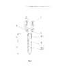
Заявляемая полезная модель поясняется чертежами.The inventive utility model is illustrated by drawings.
На фигуре 1 представлен транспедикулярный полиаксиальный винт в аксонометрии.The figure 1 presents the transpedicular polyaxial screw in a perspective view.
На фигуре 2 представлено схематичное изображение конусообразной сердцевины стержня винта, которая выполнена с образованием двух частей разной конусности.The figure 2 presents a schematic representation of the conical core of the screw shaft, which is made with the formation of two parts of different tapers.
На фигуре 3 представлен транспедикулярный полиаксиальный винт в сборе с блокирующим винтом и продольным стержнем.The figure 3 presents the transpedicular polyaxial screw assembly with a locking screw and a longitudinal shaft.
На фигуре 4 представлен блокирующий винт в сеченииThe figure 4 presents the locking screw in cross section
На фигуре 5 представлен блокирующий винт (вид сверху) с ориентирующей насечкой.The figure 5 presents the locking screw (top view) with an orienting notch.
Транспедикулярный полиаксиальный винт, содержит стержень винта 1 и головку 2. Стержень винта 1 выполнен на одном конце с резьбой 3 на рабочей части, а на другом конце со сферическим утолщением 4. Головка 2 выполнена со сквозным отверстием 5, с возможностью установки в верхнюю часть сквозного отверстия 5, имеющую внутреннюю упорную резьбу 6, блокирующего винта 7. В нижней части сквозного отверстия 5 размещено сферическое утолщение 4 стержня винта 1 и выполнен паз 8 для установки в него продольного стержня 9.The transpedicular polyaxial screw contains a
Сферическое утолщение 4 стержня винта 1 в месте контакта его с продольным стержнем 9 выполнено с насечкой 10. Насечка 10 может быть выполнена в виде концентрической или спиральной нарезки.The
Профиль резьбы 3 рабочей части стержня винта 1 переменный и представляет собой неравнобедренную трапецию 11, при этом основания трапеции 11 уменьшаются от сферического утолщения 4 стержня винта 1 к его кончику 1 2. В частности, профиль резьбы 3 рабочей части стержня винта 1 изменяется от трапециевидного у сферического утолщения 4 до треугольного возле кончика 12. Углы 13.1 и 13.2 неравнобедренной трапеции 11 профиля резьбы 3 рабочей части стержня винта 1, в частности, составляют 5° и 40°. По крайней мере, первый от кончика 12 стержня винта 1 виток резьбы 3 выполнен с выемкой 14, образующей стружечную канавку с режущими кромками.The
Наружный диаметр рабочей части стержня винта 1 постоянен, а внутренний - уменьшается от сферического утолщения 4 к кончику 12 с образованием конусообразной сердцевины 15 стержня винта 1. При этом конусообразная сердцевина 15 стержня винта 1 выполнена с образованием двух частей 15.1 и 15.2 разной конусности с переходом одной части 15.1 в другую 15.2 и с уменьшением угла наклона образующей конуса конечной части 15.2 конусообразной сердцевины 15 стержня винта 1. Стержень винта 1 имеет возможность поворота относительно головки 2, а его сферическое утолщение 4 содержит элемент 16, позволяющий создать крутящий момент относительно оси стержня винта 1. В частности, элемент 16, позволяющий создать крутящий момент относительно оси стержня винта 1, представляет собой четыре паза 16.1, 16.2, 16.3 и 16.4, симметрично расположенные на сферическом утолщении 4 стержня винта 1.The outer diameter of the working part of the shaft of the
Блокирующий винт 7 выполнен с наружной резьбой 17, соответствующей внутренней упорной резьбе 6 в верхней части сквозного отверстия 5, и с элементом 18, позволяющим приложить крутящий момент для вворачивания блокирующего винта 7 в головку 2. Элемент 18 представляет собой внутренний шестигранник, а на верхней плоскости блокирующего винта 7 выполнена ориентирующая насечка 19.The
Преимущественное выполнение транспедикулярного полиаксиального винта предполагает выполнение его с шагом резьбы 3 рабочей части стержня винта 1 равной 2,5 мм при наружном диаметре рабочей части стержня винта 1 в пределах 4,5-5,5 мм, и с шагом резьбы 3 рабочей части стержня винта 1 равной 3,0 мм при наружном диаметре рабочей части стержня винта 1 в пределах 6,5-7,5 мм.The predominant embodiment of the transpedicular polyaxial screw involves its execution with a
Преимущественное выполнение стержня винта 1 предполагает выполнение его с конусообразной сердцевиной с образованием двух частей 15.1 и 15.2 при соотношении длин частей соответственно как 1:2.The predominant embodiment of the shaft of the
Транспедикулярный полиаксиальный винт изготовлен из биосовместимого титанового сплава и подвергнут цветному анодированию для усиления совместимости с костной тканью. Кроме того, с помощью цветного анодирования транспедикулярный полиаксиальный винт маркируется по диаметру, а именно: транспедикулярный полиаксиальный винт с наружным диаметром 4,5 мм. имеет золотистый цвет, транспедикулярный полиаксиальный винт с наружным диаметром 5,5 мм. имеет синий цвет, транспедикулярный полиаксиальный винт с наружным диаметром 6,5 мм. имеет розовый цвет, а транспедикулярный полиаксиальный винт с наружным диаметром 7,5 мм. имеет зеленый цвет.The transpedicular polyaxial screw is made of a biocompatible titanium alloy and color-anodized to enhance bone compatibility. In addition, using color anodization, the transpedicular polyaxial screw is marked in diameter, namely, the transpedicular polyaxial screw with an outer diameter of 4.5 mm. has a golden color, transpedicular polyaxial screw with an outer diameter of 5.5 mm. has a blue color, transpedicular polyaxial screw with an outer diameter of 6.5 mm. has a pink color, and a transpedicular polyaxial screw with an outer diameter of 7.5 mm. has a green color.
Транспедикулярный полиаксиальный винт является составной частью устройств фиксации позвоночника и устанавливается (монтируется) следующим образом.The transpedicular polyaxial screw is an integral part of spinal fixation devices and is installed (mounted) as follows.
В позвонки, расположенные в непосредственной близости к требующим фиксации позвонкам, вворачивают транспедикулярные полиаксиальные винты заявленной конструкции.The vertebrae located in close proximity to the vertebrae requiring fixation are screwed with transpedicular polyaxial screws of the claimed design.
Установленный транспедикулярный полиаксиальный винт, благодаря профилю резьбы 3 рабочей части стержня винта 1 и выполнению стержня винта 1 с конусообразной сердцевиной с образованием двух частей 15.1 и 15.2 разной конусности с переходом одной части в другую и с уменьшением угла наклона образующей конуса конечной части 15.2 конусообразной сердцевины стержня винта 1, при том, что, по крайней мере, первый от кончика стержня винта 1 виток резьбы 3 выполнен с выемкой 14, образующей стружечную канавку с режущими кромками, позволяет снизить риск поломки стержня винта 1 и обеспечивает одинаково прочную фиксацию его как в компактной кости ножки позвонка, так и в губчатой кости тела позвонка. Данное выполнение стержня винта 1 значительно облегчает введение транспедикулярного полиаксиального винта в костную ткань позвонка и позволяет сохранять стабильность его положения в теле позвонка.Installed transpedicular polyaxial screw, due to the
Далее в пазы 8, выполненные в головках 2 транспедикулярных полиаксиальных винтов, устанавливают продольные стержни 9 цилиндрической формы, которые затем фиксируют с помощью блокирующих винтов 7. При этом выполнение на верхней плоскости блокирующего винта 7 ориентирующей насечки 19 облегчает установку блокирующего винта во время монтажа (установки) устройства фиксации позвоночника.Next, in the grooves 8 made in the
Смонтированное устройство фиксации позвоночника, составной частью которого является устройство транспедикулярного полиаксиального винта, благодаря конструктивному выполнению его составляющих, сохраняет стабильность положения во время его использования, обеспечивая, таким образом, надежную фиксацию позвонков при травмах и заболеваниях позвоночника.The mounted device for fixing the spine, a component of which is the device of the transpedicular polyaxial screw, due to the constructive implementation of its components, maintains a stable position during its use, thus ensuring reliable fixation of the vertebrae in case of injuries and diseases of the spine.
Данная конструкция транспедикулярного полиаксиального винта повышает доступность оказания высокотехнологичной хирургической помощи при травмах и заболеваниях позвоночника.This design of the transpedicular polyaxial screw increases the availability of high-tech surgical care for injuries and diseases of the spine.
Claims (5)
Translated fromRussian
Priority Applications (1)
| Application Number | Priority Date | Filing Date | Title |
|---|---|---|---|
| RU2016103447/14URU163628U1 (en) | 2016-02-02 | 2016-02-02 | TRANSPEDICULAR POLIAXIAL SCREW |
Applications Claiming Priority (1)
| Application Number | Priority Date | Filing Date | Title |
|---|---|---|---|
| RU2016103447/14URU163628U1 (en) | 2016-02-02 | 2016-02-02 | TRANSPEDICULAR POLIAXIAL SCREW |
Publications (1)
| Publication Number | Publication Date |
|---|---|
| RU163628U1true RU163628U1 (en) | 2016-07-27 |
Family
ID=56557368
Family Applications (1)
| Application Number | Title | Priority Date | Filing Date |
|---|---|---|---|
| RU2016103447/14URU163628U1 (en) | 2016-02-02 | 2016-02-02 | TRANSPEDICULAR POLIAXIAL SCREW |
Country Status (1)
| Country | Link |
|---|---|
| RU (1) | RU163628U1 (en) |
Cited By (1)
| Publication number | Priority date | Publication date | Assignee | Title |
|---|---|---|---|---|
| WO2023041951A1 (en)* | 2021-09-14 | 2023-03-23 | Agmspine, Sia | A polyaxial spinal screw |
- 2016
- 2016-02-02RURU2016103447/14Upatent/RU163628U1/enactive
Cited By (1)
| Publication number | Priority date | Publication date | Assignee | Title |
|---|---|---|---|---|
| WO2023041951A1 (en)* | 2021-09-14 | 2023-03-23 | Agmspine, Sia | A polyaxial spinal screw |
Similar Documents
| Publication | Publication Date | Title |
|---|---|---|
| US9339315B2 (en) | Bone fixation system with curved profile threads | |
| EP2364657B1 (en) | Bone fixation system with curved profile threads | |
| JP5510860B2 (en) | Fixing device, set screw, use of set screw, combination of fixing device and longitudinal element, configuration with combination and retaining structure, and osteosynthesis set | |
| JP5101597B2 (en) | Bone stabilization system including a multi-directional threaded fixation element | |
| US9642662B2 (en) | Locking spiral anchoring system | |
| AU2010262817B2 (en) | Triple lead bone screw | |
| CN102949232B (en) | Polyaxial bone anchoring device | |
| EP2085040A1 (en) | Tool for holding or guiding a receiving part for connecting a shank of a bone anchoring element to a rod | |
| KR20150028207A (en) | Bone anchor and bone anchor assembly comprising the same | |
| US20050245933A1 (en) | Multi coaxial screw system | |
| JP2019506993A (en) | Implant device | |
| RU163628U1 (en) | TRANSPEDICULAR POLIAXIAL SCREW | |
| US11701147B2 (en) | Bone anchor for triangular iliosacral osteosynthesis | |
| US9763718B2 (en) | Bone screw | |
| US20150289916A1 (en) | Bone screws having more than three leads | |
| US11298157B2 (en) | Closure assembly for securing a stabilization element in a receiving part of a bone anchoring device | |
| RU163479U1 (en) | TRANSPEDICULAR MONOAXIAL SCREW DEVICE | |
| RU154118U1 (en) | TRANSPEDICULAR POLYAXIAL SCREW DEVICE | |
| RU151639U1 (en) | TRANSPEDICULAR MONOAXIAL SCREW DEVICE | |
| RU2641376C2 (en) | Noncircular transpedicular screw | |
| RU2283630C2 (en) | Device for osteosynthesis |