KR970002742B1 - Network and intelligent cells to provide detection and bidirectional communication and control - Google Patents
Network and intelligent cells to provide detection and bidirectional communication and controlDownload PDFInfo
- Publication number
- KR970002742B1 KR970002742B1KR1019890701296AKR890701296AKR970002742B1KR 970002742 B1KR970002742 B1KR 970002742B1KR 1019890701296 AKR1019890701296 AKR 1019890701296AKR 890701296 AKR890701296 AKR 890701296AKR 970002742 B1KR970002742 B1KR 970002742B1
- Authority
- KR
- South Korea
- Prior art keywords
- cell
- group
- cells
- network
- processor
- Prior art date
- Legal status (The legal status is an assumption and is not a legal conclusion. Google has not performed a legal analysis and makes no representation as to the accuracy of the status listed.)
- Expired - Lifetime
Links
- 238000001514detection methodMethods0.000titleclaimsdescription16
- 230000007175bidirectional communicationEffects0.000titledescription3
- 230000006854communicationEffects0.000claimsabstractdescription86
- 238000004891communicationMethods0.000claimsabstractdescription86
- 230000006870functionEffects0.000claimsabstractdescription68
- 238000000034methodMethods0.000claimsdescription43
- 230000004044responseEffects0.000claimsdescription19
- 238000012545processingMethods0.000claimsdescription14
- 230000008439repair processEffects0.000claimsdescription14
- 230000008859changeEffects0.000claimsdescription8
- 238000006243chemical reactionMethods0.000claimsdescription7
- 239000000758substrateSubstances0.000claimsdescription7
- 230000009471actionEffects0.000claimsdescription3
- 238000003860storageMethods0.000claimsdescription3
- 239000004065semiconductorSubstances0.000claims6
- 230000008878couplingEffects0.000claims4
- 238000010168coupling processMethods0.000claims4
- 238000005859coupling reactionMethods0.000claims4
- 238000004590computer programMethods0.000claims1
- 238000004519manufacturing processMethods0.000abstractdescription7
- 230000005540biological transmissionEffects0.000description35
- 238000010586diagramMethods0.000description28
- 239000000523sampleSubstances0.000description27
- 230000007704transitionEffects0.000description25
- 230000008569processEffects0.000description18
- 230000003287optical effectEffects0.000description13
- 238000004364calculation methodMethods0.000description11
- 230000001360synchronised effectEffects0.000description9
- 230000007246mechanismEffects0.000description7
- 230000000873masking effectEffects0.000description5
- 230000003213activating effectEffects0.000description4
- 230000003111delayed effectEffects0.000description4
- 238000009434installationMethods0.000description4
- 230000002829reductive effectEffects0.000description4
- 235000008694Humulus lupulusNutrition0.000description3
- 239000003990capacitorSubstances0.000description3
- 238000006073displacement reactionMethods0.000description3
- 238000005516engineering processMethods0.000description3
- 229920006395saturated elastomerPolymers0.000description3
- 230000003068static effectEffects0.000description3
- 241000605059BacteroidetesSpecies0.000description2
- XUIMIQQOPSSXEZ-UHFFFAOYSA-NSiliconChemical compound[Si]XUIMIQQOPSSXEZ-UHFFFAOYSA-N0.000description2
- 230000002457bidirectional effectEffects0.000description2
- 230000015572biosynthetic processEffects0.000description2
- 230000008568cell cell communicationEffects0.000description2
- 230000000295complement effectEffects0.000description2
- 238000012790confirmationMethods0.000description2
- 239000000835fiberSubstances0.000description2
- 238000007689inspectionMethods0.000description2
- 238000012423maintenanceMethods0.000description2
- 230000010363phase shiftEffects0.000description2
- 229910052710siliconInorganic materials0.000description2
- 239000010703siliconSubstances0.000description2
- 238000012546transferMethods0.000description2
- 238000012795verificationMethods0.000description2
- OFFWOVJBSQMVPI-RMLGOCCBSA-NKaletraChemical compoundN1([C@@H](C(C)C)C(=O)N[C@H](C[C@H](O)[C@H](CC=2C=CC=CC=2)NC(=O)COC=2C(=CC=CC=2C)C)CC=2C=CC=CC=2)CCCNC1=O.N([C@@H](C(C)C)C(=O)N[C@H](C[C@H](O)[C@H](CC=1C=CC=CC=1)NC(=O)OCC=1SC=NC=1)CC=1C=CC=CC=1)C(=O)N(C)CC1=CSC(C(C)C)=N1OFFWOVJBSQMVPI-RMLGOCCBSA-N0.000description1
- 230000002238attenuated effectEffects0.000description1
- 238000013475authorizationMethods0.000description1
- 230000008901benefitEffects0.000description1
- 230000003139buffering effectEffects0.000description1
- 230000003915cell functionEffects0.000description1
- 239000013078crystalSubstances0.000description1
- 125000004122cyclic groupChemical group0.000description1
- 230000003247decreasing effectEffects0.000description1
- 230000007547defectEffects0.000description1
- 230000001934delayEffects0.000description1
- 238000013461designMethods0.000description1
- 230000000694effectsEffects0.000description1
- 239000000284extractSubstances0.000description1
- 238000007667floatingMethods0.000description1
- 230000014509gene expressionEffects0.000description1
- 230000010365information processingEffects0.000description1
- 230000000670limiting effectEffects0.000description1
- 238000012544monitoring processMethods0.000description1
- 239000003921oilSubstances0.000description1
- 239000013307optical fiberSubstances0.000description1
- 230000008520organizationEffects0.000description1
- 230000001681protective effectEffects0.000description1
- 230000003252repetitive effectEffects0.000description1
- 230000002441reversible effectEffects0.000description1
- 238000012163sequencing techniqueMethods0.000description1
- 230000007480spreadingEffects0.000description1
- 238000003892spreadingMethods0.000description1
- 238000013519translationMethods0.000description1
- 238000004804windingMethods0.000description1
Images


Classifications
- H—ELECTRICITY
- H04—ELECTRIC COMMUNICATION TECHNIQUE
- H04Q—SELECTING
- H04Q3/00—Selecting arrangements
- G—PHYSICS
- G05—CONTROLLING; REGULATING
- G05B—CONTROL OR REGULATING SYSTEMS IN GENERAL; FUNCTIONAL ELEMENTS OF SUCH SYSTEMS; MONITORING OR TESTING ARRANGEMENTS FOR SUCH SYSTEMS OR ELEMENTS
- G05B19/00—Programme-control systems
- G05B19/02—Programme-control systems electric
- G05B19/04—Programme control other than numerical control, i.e. in sequence controllers or logic controllers
- G05B19/042—Programme control other than numerical control, i.e. in sequence controllers or logic controllers using digital processors
- G05B19/0421—Multiprocessor system
- G—PHYSICS
- G08—SIGNALLING
- G08C—TRANSMISSION SYSTEMS FOR MEASURED VALUES, CONTROL OR SIMILAR SIGNALS
- G08C15/00—Arrangements characterised by the use of multiplexing for the transmission of a plurality of signals over a common path
- H—ELECTRICITY
- H04—ELECTRIC COMMUNICATION TECHNIQUE
- H04L—TRANSMISSION OF DIGITAL INFORMATION, e.g. TELEGRAPHIC COMMUNICATION
- H04L12/00—Data switching networks
- H04L12/28—Data switching networks characterised by path configuration, e.g. LAN [Local Area Networks] or WAN [Wide Area Networks]
- H04L12/2803—Home automation networks
- H04L12/2816—Controlling appliance services of a home automation network by calling their functionalities
- H04L12/282—Controlling appliance services of a home automation network by calling their functionalities based on user interaction within the home
- H—ELECTRICITY
- H04—ELECTRIC COMMUNICATION TECHNIQUE
- H04L—TRANSMISSION OF DIGITAL INFORMATION, e.g. TELEGRAPHIC COMMUNICATION
- H04L12/00—Data switching networks
- H04L12/28—Data switching networks characterised by path configuration, e.g. LAN [Local Area Networks] or WAN [Wide Area Networks]
- H04L12/2803—Home automation networks
- H04L12/2838—Distribution of signals within a home automation network, e.g. involving splitting/multiplexing signals to/from different paths
- H—ELECTRICITY
- H04—ELECTRIC COMMUNICATION TECHNIQUE
- H04W—WIRELESS COMMUNICATION NETWORKS
- H04W12/00—Security arrangements; Authentication; Protecting privacy or anonymity
- H04W12/08—Access security
- H—ELECTRICITY
- H05—ELECTRIC TECHNIQUES NOT OTHERWISE PROVIDED FOR
- H05B—ELECTRIC HEATING; ELECTRIC LIGHT SOURCES NOT OTHERWISE PROVIDED FOR; CIRCUIT ARRANGEMENTS FOR ELECTRIC LIGHT SOURCES, IN GENERAL
- H05B47/00—Circuit arrangements for operating light sources in general, i.e. where the type of light source is not relevant
- H05B47/10—Controlling the light source
- H05B47/155—Coordinated control of two or more light sources
- G—PHYSICS
- G05—CONTROLLING; REGULATING
- G05B—CONTROL OR REGULATING SYSTEMS IN GENERAL; FUNCTIONAL ELEMENTS OF SUCH SYSTEMS; MONITORING OR TESTING ARRANGEMENTS FOR SUCH SYSTEMS OR ELEMENTS
- G05B2219/00—Program-control systems
- G05B2219/20—Pc systems
- G05B2219/21—Pc I-O input output
- G05B2219/21042—Address a group, a zone
- G—PHYSICS
- G05—CONTROLLING; REGULATING
- G05B—CONTROL OR REGULATING SYSTEMS IN GENERAL; FUNCTIONAL ELEMENTS OF SUCH SYSTEMS; MONITORING OR TESTING ARRANGEMENTS FOR SUCH SYSTEMS OR ELEMENTS
- G05B2219/00—Program-control systems
- G05B2219/20—Pc systems
- G05B2219/21—Pc I-O input output
- G05B2219/21053—Each unit, module has unique identification code, set during manufacturing, fMAC address
- G—PHYSICS
- G05—CONTROLLING; REGULATING
- G05B—CONTROL OR REGULATING SYSTEMS IN GENERAL; FUNCTIONAL ELEMENTS OF SUCH SYSTEMS; MONITORING OR TESTING ARRANGEMENTS FOR SUCH SYSTEMS OR ELEMENTS
- G05B2219/00—Program-control systems
- G05B2219/20—Pc systems
- G05B2219/25—Pc structure of the system
- G05B2219/25086—Assign functions to group of complete or partial cells, modules
- G—PHYSICS
- G05—CONTROLLING; REGULATING
- G05B—CONTROL OR REGULATING SYSTEMS IN GENERAL; FUNCTIONAL ELEMENTS OF SUCH SYSTEMS; MONITORING OR TESTING ARRANGEMENTS FOR SUCH SYSTEMS OR ELEMENTS
- G05B2219/00—Program-control systems
- G05B2219/20—Pc systems
- G05B2219/25—Pc structure of the system
- G05B2219/25162—Contention, if several transmitters avoid collision, by separate transmittor code
- G—PHYSICS
- G05—CONTROLLING; REGULATING
- G05B—CONTROL OR REGULATING SYSTEMS IN GENERAL; FUNCTIONAL ELEMENTS OF SUCH SYSTEMS; MONITORING OR TESTING ARRANGEMENTS FOR SUCH SYSTEMS OR ELEMENTS
- G05B2219/00—Program-control systems
- G05B2219/20—Pc systems
- G05B2219/25—Pc structure of the system
- G05B2219/25163—Transmit twice, redundant, same data on different channels, check each channel
- G—PHYSICS
- G05—CONTROLLING; REGULATING
- G05B—CONTROL OR REGULATING SYSTEMS IN GENERAL; FUNCTIONAL ELEMENTS OF SUCH SYSTEMS; MONITORING OR TESTING ARRANGEMENTS FOR SUCH SYSTEMS OR ELEMENTS
- G05B2219/00—Program-control systems
- G05B2219/20—Pc systems
- G05B2219/25—Pc structure of the system
- G05B2219/25178—Serial communication, data, also repeater
- G—PHYSICS
- G05—CONTROLLING; REGULATING
- G05B—CONTROL OR REGULATING SYSTEMS IN GENERAL; FUNCTIONAL ELEMENTS OF SUCH SYSTEMS; MONITORING OR TESTING ARRANGEMENTS FOR SUCH SYSTEMS OR ELEMENTS
- G05B2219/00—Program-control systems
- G05B2219/20—Pc systems
- G05B2219/25—Pc structure of the system
- G05B2219/25187—Transmission of signals, medium, ultrasonic, radio
- G—PHYSICS
- G05—CONTROLLING; REGULATING
- G05B—CONTROL OR REGULATING SYSTEMS IN GENERAL; FUNCTIONAL ELEMENTS OF SUCH SYSTEMS; MONITORING OR TESTING ARRANGEMENTS FOR SUCH SYSTEMS OR ELEMENTS
- G05B2219/00—Program-control systems
- G05B2219/20—Pc systems
- G05B2219/25—Pc structure of the system
- G05B2219/25192—Infrared
- G—PHYSICS
- G05—CONTROLLING; REGULATING
- G05B—CONTROL OR REGULATING SYSTEMS IN GENERAL; FUNCTIONAL ELEMENTS OF SUCH SYSTEMS; MONITORING OR TESTING ARRANGEMENTS FOR SUCH SYSTEMS OR ELEMENTS
- G05B2219/00—Program-control systems
- G05B2219/20—Pc systems
- G05B2219/25—Pc structure of the system
- G05B2219/25193—Coaxial cable
- G—PHYSICS
- G05—CONTROLLING; REGULATING
- G05B—CONTROL OR REGULATING SYSTEMS IN GENERAL; FUNCTIONAL ELEMENTS OF SUCH SYSTEMS; MONITORING OR TESTING ARRANGEMENTS FOR SUCH SYSTEMS OR ELEMENTS
- G05B2219/00—Program-control systems
- G05B2219/20—Pc systems
- G05B2219/25—Pc structure of the system
- G05B2219/25196—Radio link, transponder
- G—PHYSICS
- G05—CONTROLLING; REGULATING
- G05B—CONTROL OR REGULATING SYSTEMS IN GENERAL; FUNCTIONAL ELEMENTS OF SUCH SYSTEMS; MONITORING OR TESTING ARRANGEMENTS FOR SUCH SYSTEMS OR ELEMENTS
- G05B2219/00—Program-control systems
- G05B2219/20—Pc systems
- G05B2219/25—Pc structure of the system
- G05B2219/25197—Optical, glass fiber
- G—PHYSICS
- G05—CONTROLLING; REGULATING
- G05B—CONTROL OR REGULATING SYSTEMS IN GENERAL; FUNCTIONAL ELEMENTS OF SUCH SYSTEMS; MONITORING OR TESTING ARRANGEMENTS FOR SUCH SYSTEMS OR ELEMENTS
- G05B2219/00—Program-control systems
- G05B2219/20—Pc systems
- G05B2219/25—Pc structure of the system
- G05B2219/25219—Probe packet to determine best route for messages
- G—PHYSICS
- G05—CONTROLLING; REGULATING
- G05B—CONTROL OR REGULATING SYSTEMS IN GENERAL; FUNCTIONAL ELEMENTS OF SUCH SYSTEMS; MONITORING OR TESTING ARRANGEMENTS FOR SUCH SYSTEMS OR ELEMENTS
- G05B2219/00—Program-control systems
- G05B2219/20—Pc systems
- G05B2219/25—Pc structure of the system
- G05B2219/25234—Direct communication between two modules instead of normal network
- G—PHYSICS
- G05—CONTROLLING; REGULATING
- G05B—CONTROL OR REGULATING SYSTEMS IN GENERAL; FUNCTIONAL ELEMENTS OF SUCH SYSTEMS; MONITORING OR TESTING ARRANGEMENTS FOR SUCH SYSTEMS OR ELEMENTS
- G05B2219/00—Program-control systems
- G05B2219/20—Pc systems
- G05B2219/26—Pc applications
- G05B2219/2642—Domotique, domestic, home control, automation, smart house
- H—ELECTRICITY
- H04—ELECTRIC COMMUNICATION TECHNIQUE
- H04L—TRANSMISSION OF DIGITAL INFORMATION, e.g. TELEGRAPHIC COMMUNICATION
- H04L12/00—Data switching networks
- H04L12/28—Data switching networks characterised by path configuration, e.g. LAN [Local Area Networks] or WAN [Wide Area Networks]
- H04L12/2803—Home automation networks
- H04L12/2807—Exchanging configuration information on appliance services in a home automation network
- H04L12/2814—Exchanging control software or macros for controlling appliance services in a home automation network
- H—ELECTRICITY
- H04—ELECTRIC COMMUNICATION TECHNIQUE
- H04L—TRANSMISSION OF DIGITAL INFORMATION, e.g. TELEGRAPHIC COMMUNICATION
- H04L12/00—Data switching networks
- H04L12/28—Data switching networks characterised by path configuration, e.g. LAN [Local Area Networks] or WAN [Wide Area Networks]
- H04L12/2803—Home automation networks
- H04L12/2823—Reporting information sensed by appliance or service execution status of appliance services in a home automation network
- H—ELECTRICITY
- H04—ELECTRIC COMMUNICATION TECHNIQUE
- H04L—TRANSMISSION OF DIGITAL INFORMATION, e.g. TELEGRAPHIC COMMUNICATION
- H04L12/00—Data switching networks
- H04L12/28—Data switching networks characterised by path configuration, e.g. LAN [Local Area Networks] or WAN [Wide Area Networks]
- H04L12/2803—Home automation networks
- H04L2012/284—Home automation networks characterised by the type of medium used
- H04L2012/2841—Wireless
- H—ELECTRICITY
- H04—ELECTRIC COMMUNICATION TECHNIQUE
- H04L—TRANSMISSION OF DIGITAL INFORMATION, e.g. TELEGRAPHIC COMMUNICATION
- H04L12/00—Data switching networks
- H04L12/28—Data switching networks characterised by path configuration, e.g. LAN [Local Area Networks] or WAN [Wide Area Networks]
- H04L12/2803—Home automation networks
- H04L2012/284—Home automation networks characterised by the type of medium used
- H04L2012/2843—Mains power line
- H—ELECTRICITY
- H04—ELECTRIC COMMUNICATION TECHNIQUE
- H04L—TRANSMISSION OF DIGITAL INFORMATION, e.g. TELEGRAPHIC COMMUNICATION
- H04L12/00—Data switching networks
- H04L12/28—Data switching networks characterised by path configuration, e.g. LAN [Local Area Networks] or WAN [Wide Area Networks]
- H04L12/2803—Home automation networks
- H04L2012/2847—Home automation networks characterised by the type of home appliance used
- H04L2012/285—Generic home appliances, e.g. refrigerators
- H—ELECTRICITY
- H04—ELECTRIC COMMUNICATION TECHNIQUE
- H04L—TRANSMISSION OF DIGITAL INFORMATION, e.g. TELEGRAPHIC COMMUNICATION
- H04L63/00—Network architectures or network communication protocols for network security
- H04L63/10—Network architectures or network communication protocols for network security for controlling access to devices or network resources
- H04L63/104—Grouping of entities
- Y—GENERAL TAGGING OF NEW TECHNOLOGICAL DEVELOPMENTS; GENERAL TAGGING OF CROSS-SECTIONAL TECHNOLOGIES SPANNING OVER SEVERAL SECTIONS OF THE IPC; TECHNICAL SUBJECTS COVERED BY FORMER USPC CROSS-REFERENCE ART COLLECTIONS [XRACs] AND DIGESTS
- Y02—TECHNOLOGIES OR APPLICATIONS FOR MITIGATION OR ADAPTATION AGAINST CLIMATE CHANGE
- Y02B—CLIMATE CHANGE MITIGATION TECHNOLOGIES RELATED TO BUILDINGS, e.g. HOUSING, HOUSE APPLIANCES OR RELATED END-USER APPLICATIONS
- Y02B20/00—Energy efficient lighting technologies, e.g. halogen lamps or gas discharge lamps
- Y02B20/40—Control techniques providing energy savings, e.g. smart controller or presence detection
- Y—GENERAL TAGGING OF NEW TECHNOLOGICAL DEVELOPMENTS; GENERAL TAGGING OF CROSS-SECTIONAL TECHNOLOGIES SPANNING OVER SEVERAL SECTIONS OF THE IPC; TECHNICAL SUBJECTS COVERED BY FORMER USPC CROSS-REFERENCE ART COLLECTIONS [XRACs] AND DIGESTS
- Y02—TECHNOLOGIES OR APPLICATIONS FOR MITIGATION OR ADAPTATION AGAINST CLIMATE CHANGE
- Y02D—CLIMATE CHANGE MITIGATION TECHNOLOGIES IN INFORMATION AND COMMUNICATION TECHNOLOGIES [ICT], I.E. INFORMATION AND COMMUNICATION TECHNOLOGIES AIMING AT THE REDUCTION OF THEIR OWN ENERGY USE
- Y02D30/00—Reducing energy consumption in communication networks
- Y02D30/70—Reducing energy consumption in communication networks in wireless communication networks
- Y—GENERAL TAGGING OF NEW TECHNOLOGICAL DEVELOPMENTS; GENERAL TAGGING OF CROSS-SECTIONAL TECHNOLOGIES SPANNING OVER SEVERAL SECTIONS OF THE IPC; TECHNICAL SUBJECTS COVERED BY FORMER USPC CROSS-REFERENCE ART COLLECTIONS [XRACs] AND DIGESTS
- Y02—TECHNOLOGIES OR APPLICATIONS FOR MITIGATION OR ADAPTATION AGAINST CLIMATE CHANGE
- Y02P—CLIMATE CHANGE MITIGATION TECHNOLOGIES IN THE PRODUCTION OR PROCESSING OF GOODS
- Y02P80/00—Climate change mitigation technologies for sector-wide applications
- Y02P80/10—Efficient use of energy, e.g. using compressed air or pressurized fluid as energy carrier
Landscapes
- Engineering & Computer Science (AREA)
- Computer Networks & Wireless Communication (AREA)
- Signal Processing (AREA)
- Automation & Control Theory (AREA)
- Computer Security & Cryptography (AREA)
- General Physics & Mathematics (AREA)
- Physics & Mathematics (AREA)
- Multimedia (AREA)
- Human Computer Interaction (AREA)
- Small-Scale Networks (AREA)
- Data Exchanges In Wide-Area Networks (AREA)
- Multi Processors (AREA)
- Mobile Radio Communication Systems (AREA)
- Superconductors And Manufacturing Methods Therefor (AREA)
- Burglar Alarm Systems (AREA)
- Immobilizing And Processing Of Enzymes And Microorganisms (AREA)
- Medicines Containing Material From Animals Or Micro-Organisms (AREA)
Abstract
Description
Translated fromKorean[발명의 명칭][Name of invention]
감지와 양방향 통신 및 제어를 제공하기 위한 네트워크 및 지능셀Network and intelligent cells to provide detection and bidirectional communication and control
[도면의 간단한 설명][Brief Description of Drawings]
제 1 도는 본 발명의 전형적인 적용을 설명하기 위한 블록도이고,1 is a block diagram illustrating a typical application of the present invention,
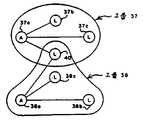
제 2 도는 셀그룹을 설명하기 위한 도면,2 is a diagram for explaining a cell group;
제 3 도는 셀그룹을 설명하기 위한 제 2 도에 대응되는 다른 블록도,FIG. 3 is another block diagram corresponding to FIG. 2 for explaining a cell group.
제 4 도는 서브챈널을 설명하기 위한 도면,4 is a diagram for explaining a subchannel,
제 5 도는 복수의 셀을 설명하기 위한 것으로서, 본 발명에 의한 셀구룹 형성을 설명하기 위한 도면,5 is for explaining a plurality of cells, a diagram for explaining the formation of a cell group according to the present invention,
제 6 도는 본 발명에 사용되는 패킷포맷을 설명하기 위한 차트,6 is a chart for explaining the packet format used in the present invention;
제 7 도는 제 6 도에 도시된 패킷포맷의 명칭리스트부를 설명하기 위한 챠트,7 is a chart for explaining the name list portion of the packet format shown in FIG. 6;
제 8 도는 본 발명에서 셀그룹 형성에 사용되는 일련의 스텝을 설명하기 위한 도면,8 is a view for explaining a series of steps used to form a cell group in the present invention,
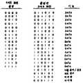
제 9 도는 본 발명에 사용되는 3 대 6 인코딩을 위한 코드할당을 설명하기 위한 챠트,9 is a chart for explaining code allocation for 3 to 6 encoding used in the present invention;
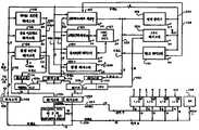
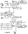
제 10 도는 통신과 제어셀을 도시해 놓은 블럭도,10 is a block diagram showing a communication and control cell,
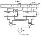
제 11도는 제 10 도에 도시된 셀 중 프로세서내에 사용되는 명령디코딩로직부를 도시해 놓은 블록도,FIG. 11 is a block diagram showing an instruction decoding logic unit used in a processor among the cells shown in FIG. 10;
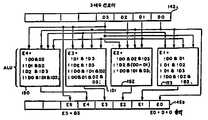
제 12 도는 제 10 도중 프로세서의 상시블록도,12 is a constant block diagram of a processor during the 10th time,
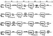
제 13 도는 제 10 도에 도시된 프로세서의 타이밍도로서, 셀에 의해 사용되는 파이플링을 제공하기 위해 사용되는 래치 및 레지스터를 도시해 놓은 도면,FIG. 13 is a timing diagram of the processor shown in FIG. 10, illustrating latches and registers used to provide piping used by a cell;
제 14 도는 본 실시예의 3 대 6 인코더를 설명하기 위한 블록도,14 is a block diagram for explaining a three-to-sixth encoder of this embodiment;
제 15 도는 본 실시예에서의 3 대 6 디코더를 도시해 놓은 블록도,15 is a block diagram showing three to six decoders in this embodiment;
제 16 도는 본 실시예의 3 대 6 코드검색기를 도시해 놓은 블록도,16 is a block diagram showing a 3 to 6 code searcher of this embodiment,
제 17 도는 I/O 섹션중 하나의 버퍼섹션을 개략적으로 도시해 놓은 전기회로도,17 is an electrical circuit diagram schematically showing a buffer section of one of the I / O sections,
제 18 도는 I/O 서브섹션용의 카운팅 및 타이밍기능을 개략적으로 도시해 놓은 전기회로도,18 is an electrical circuit diagram schematically showing counting and timing functions for an I / O subsection,
제 19 도는 I/O 섹션용의 제어 및 상태머신을 개략적으로 도시해 놓은 전기회로도,19 is an electrical circuit diagram schematically showing a control and state machine for an I / O section;
제 20 도는 I/O 서브섹션과 관계된 표본 및 홀드수단을 개략적으로 도시해 놓은 전기회로도,20 is an electrical circuit diagram schematically showing a sample and hold means associated with an I / O subsection,
제 21 도는 I/O 서브섹션내에 형성되어 디지탈/아날로그 변환을 실행하는 네트워크를 설명하기 위한 도면,21 is a diagram for explaining a network formed in an I / O subsection to perform digital / analog conversion;
제 22 도는 I/O 섹션내에 형성되어 아날로그/디지탈변환을 실행하는 네트워크를 설명하기 위한 도면,FIG. 22 is a diagram for explaining a network formed in an I / O section to perform analog / digital conversion; FIG.
제 23 도는 I/O 서브섹션의 통신부를 개략적으로 도시해 놓은 전기회로도,23 is an electrical circuit diagram schematically showing a communication unit of the I / O subsection,
제 24 도는 I/O 서브섹션과 전송회선쟁탈을 위해 사용되는 상태도,24 is a state diagram used for transmission line contention with I / O subsection,
제 25 도는 링크레벨(ARQ)에 대한 상태도,25 is a state diagram for a link level (ARQ),
제 26 도는 제 1 국 접속을 위한 상태도,26 is a state diagram for connecting to a first station,
제 27 도는 제 2 국 접속을 위한 상태도,27 is a state diagram for connecting a second station,
제 28 도는 디바이스를 그룹으로 묶기 위한 상태도,28 is a state diagram for grouping devices;
제 29 도는 패킷으로 전송하기 위해 인코드되고 셀내에서 인코드된 시스템 ID에서의 형태를 도시해 놓은 도면,FIG. 29 illustrates the form in a system ID encoded and encoded in a cell for transmission in a packet;
제 30 도는 입/출력섹션과 시마포어레지스터(semaphore regster)의 동작을 설명하기 위한 도면이다.FIG. 30 is a diagram for explaining the operation of an input / output section and a semaphore regster.
[발명의 상세한 설명]Detailed description of the invention
[발명의 배경][Background of invention]
1. 발명의 분야1. Field of Invention
본 발명은 지능과, 구성 및 제어 및 지능셀을 갖추어 감지와 통신 및 제어에 사용되는 네트워크의 분야에 관한 것이다.The present invention relates to the field of networks used for sensing, communication and control with intelligence, configuration and control, and intelligent cells.
2. 종래의 기술2. Conventional Technology
네트워크 환경에서 감지와, 제어 및 통신을 제공하는 상업적으로 유용한 장치는 많이 있는데, 이들 장치는 아주 고가이고 정교한 시스템으로부터 적은 지능을 갖는 단순한 시스템으로 배열된다. 이하에서 설명할 본 발명은 많은 양의 지능 및 계산능력을 갖추면서도 비용이 적게 드는 시스템을 제공하게 된다.There are many commercially available devices that provide sensing, control and communication in a network environment, ranging from very expensive and sophisticated systems to simple systems with less intelligence. The present invention to be described below will provide a low cost system with a large amount of intelligence and computing power.
하나의 상업적으로 유용한 시스템 X-10은 예컨대 광스위치와 광사이를 제어하게 되는데, 이 광스위치가 동작되면 코드패턴은 광상태로 전력선을 타고 수신측으로 전동된다. 이 코드패턴은 2번 전동되는데, 그 한번은 그것의 실제형태(true Porm)이고, 다른 한번은 그것의 보수형태(Complementary Porm)로 전송된다. 그리고 상기 코드가 수신측에 수신되면, 이 코드의 해석에 따라 광제어가 이루어지게 된다. 기계적인 어드레싱수단은 특정한 소정 수신측에 광을 통신하기 위한 스위치에 전송기로서 사용된다.One commercially available system X-10, for example, controls between an optical switch and an optical fiber. When the optical switch is operated, the code pattern is transmitted to the receiving side by a power line in an optical state. This code pattern is transmitted twice, once in its true form, and once in its complementary form. When the code is received at the receiver, light control is performed according to the interpretation of the code. The mechanical addressing means is used as a transmitter in a switch for communicating light to a specific predetermined receiving side.
설명하는 바와 같이, 본 발명은 실질적으로 현재의 시스템에 비해 더욱 많은 능력과 유연성을 제공하게 된다.As will be described, the present invention provides substantially more power and flexibility compared to current systems.
X-10이라 표기된 종래기술이나, 다른 알려진 종래 시스템을 지원하게 될 것이다.It will support the prior art labeled X-10, or other known conventional systems.
감지와 통신 및 제어를 제공하기 위한 네트워크를 설명하면, 복수의 지능셀 각각은 그 네트워크에 결합된 프로세서와 입/출력부를 갖춘 집적회로를 포함하고 있고, 각각 프로그램이 가능한 셀은 그 셀내에 영속적으로 유지되는 독특한 식별번호(40비트)로 제조될때 인가된다. 그 셀은 전원선이나 트위스트상(twisted pair), 라디오주파수, 적외선초음파, 광축(optical coaxial)등과 같은 네트워크를 형성하기 위한 다른 매체들에 결합될 수 있다.In describing a network for providing sensing, communication, and control, each of a plurality of intelligent cells includes an integrated circuit having a processor and an input / output coupled to the network, each programmable cell permanently within that cell. Approved when manufactured with a unique identification number (40 bits) maintained. The cell can be coupled to other media to form a network, such as power lines or twisted pairs, radio frequencies, infrared ultrasonic waves, optical coaxial, and the like.
네트워크는 시스템식별번호(ID)에 의해 다른 것과 구별되는데, 각 네트워크내의 셀그룹은 특별한 기능을 수행할 수 있도록 형성됨과 더불어 그룹 ID 에 의해 특정화된다. 통신은 네트워크내에서 시스템과 그룹 ID 및 셀 ID의 사용을 통해 이루어지는 데, 몇몇 셀(어나운서)들은 감지작업, 예컨대 광제어와 같은 스위치상태와 다른 제어작업(리스너)에 할당되고, 셀은 복수의 그룹기능요소로서 복수의 작업, 예컨대 한 그룹에 대해서는 리피터, 다른 그룹에 대해서는 리스너로서 가능하게 된다. 제조시, 셀은 셀 ID 이외에는 동등한데, 이들은 그룹이나 특별한 그룹에 대한 특정한 작업을 수행하도록 프로그램되어 있다.Networks are distinguished from others by system identification numbers (IDs). Cell groups in each network are formed to perform special functions and are specified by group IDs. Communication takes place through the use of system and group IDs and cell IDs within the network, where some cells (announcers) are assigned to sensing operations, for example switch states and other control operations (listeners) such as optical control, As a group function element of plural operations, for example, a repeater for one group and a listener for another group can be enabled. At the time of manufacture, cells are equivalent to cell IDs, which are programmed to perform specific tasks for groups or special groups.
상기 실시예의 셀은 다중프로세서와, 소정 I/O 서브섹션과 통신할 수 있는 소정 프로세서가 설치된 다중 I/O 서브섹션으로 구성되어 있는데, 이러한 것에 의해 I/O 섹션과의 인터페이스에 의한 전위인터럽션 없이 프로그램을 연속적으로 실행할 수 있게 된다. 또 I/O 섹션은 프로그램이 가능한 A/D 및 D/A 변환기와 다른 동작 모드를 위한 다른 회로로 구성되어 있다.The cell of this embodiment is composed of multiple processors and multiple I / O subsections equipped with a predetermined processor capable of communicating with a predetermined I / O subsection, whereby potential interruption by interface with the I / O section is achieved. The program can be run continuously without The I / O section also consists of programmable A / D and D / A converters and other circuitry for different modes of operation.
네트워크프로토콜은 큰 유연성, 예컨대 셀이 배치된 후에 형성되거나 또는 변화되는 그룹을 형성할 수 있도록 되어 있다. 설명한 바와 같이 네트워크를 위한 지능은 셀사이에 분포되어 있다. 일반적으로 네트워크는 비록 설비가 제기되는 접속 및 다른 상태로 이루어지지만은 약하게 로드되게 된다. 일반적으로 셀사이의 통신은 네트워크를 제어기능에 관계없는 데이터의 전송보다는 그 그룹에 할당된 기능을 최적으로 실행시키기 위한 것이다. 때문에 보통 전송메시지는 에써네트(Ethernet)와, 알파, 애플토크, X-2S 및 다른 많은 광대역 및 데이터통신시스템에 비해 비교적 짧다.Network protocols allow for great flexibility, for example to form groups that are formed or changed after the cells are deployed. As described, intelligence for the network is distributed among the cells. In general, the network will be lightly loaded, although the equipment is in a different state than the connection to which it was raised. In general, communication between cells is intended to optimally execute a function assigned to a group rather than transmitting data irrelevant to a control function. Because of this, transmission messages are usually relatively short compared to Ethernet, Alpha, AppleTalk, X-2S and many other broadband and data communications systems.
본 발명의 다른 관점에 따른 네트워크 및 셀은 발명의 상세한 설명에서 분명하게 된다.Networks and cells according to other aspects of the invention will become apparent in the detailed description of the invention.
네트워크에서 통신과 감지 및 제어를 제공하는 장치 및 방법을 설명한다.An apparatus and method for providing communication, sensing and control in a network are described.
복수의 지능셀을 포함하는 네트워크에서, 셀은 일반적으로 프로그램이 가능한 단일칩원격제어, 감지 및 통신디바이스이다. 다른 셀과 각종 매채를 통해서 상호접속될때 감지, 통신, 제어 및 네트워크계산 지능, 계산 및 제어가 분포된다. 그 시스템은 통신에 필요한 계층구조로 조직화된 셀의 네트워크를 포함하는데, 셀은 네트워크계층구조의 독립적인 그룹으로 가능하도록 조직화된다. 셀의 그룹은 일반적으로 그룹기능을 수행하기 위해 사용된다. 이 기능은 그룹내의 셀에 작업을 할당함으로써 실행되는데, 셀은 제어 및 감지정보를 전달한다. 일반적으로 각 셀은 독특한 식별번호를 갖추고 양방향 통신프로토콜과 입/출력, 패킷처리 및 아날로그 및 디지탈 감지 및 제어와 같은 정보처리작업을 수행한다. 일반적으로 시스템은 그 시스템 전체에 분산된 네트워크구성 정보를 기억하는 특성을 갖는 셀을 포함하고, 셀사이에 메시지는 자동적으로 발송되어 통신된다. 각 시스템은 독특한 식별정보를 갖는데, 본 실시예에서는 이 식별정보가 48비트로 되어 있다. 더욱이 시스템은 특정한 감지와 통신, 제어 및 I/O, 아날로그 I/O 및 ,통신 I/O 및 통신비트속도감지를 위해 구성셀에 가변적으로 프로그램할 수 있는 디지탈을 갖춘 가변적으로 프로그램할 수 있는 입/출력 I/O 회로를 포함하고 있다.In a network comprising a plurality of intelligent cells, the cells are typically programmable single chip remote control, sensing, and communication devices. When interconnected with other cells through various media, detection, communication, control and network computation intelligence, computation and control are distributed. The system includes a network of cells organized into hierarchies necessary for communication, which cells are organized to enable independent groups of network hierarchies. Groups of cells are commonly used to perform group functions. This function is implemented by assigning tasks to cells in the group, which communicate control and sensing information. In general, each cell has a unique identification number and performs bidirectional communication protocols and information processing tasks such as input / output, packet processing, and analog and digital sensing and control. In general, a system includes a cell having a characteristic of storing network configuration information distributed throughout the system, and messages are automatically sent and communicated between the cells. Each system has unique identification information, which is 48 bits in this embodiment. Furthermore, the system is a variably programmable input with digitally configurable cells in the configuration cell for specific sensing and communication, control and I / O, analog I / O and communication I / O and communication bit rate detection. Contains the output I / O circuit.
이하, 본 발명의 이해를 완전하게 하기 위해 특정 주파수등과 같은 많은 특정항목을 설명한다. 그러나 이들 항목들은 본 발명이 속하는 기술분야에 해당되는 것이고, 본 발명의 실제적인 적용에 요구되는 것은 아니다. 그리고, 잘 알려진 회로나 방법에 대해서는 본 발명의 요지를 명확히 하기 위해 그 상세한 설명은 생략한다.Hereinafter, many specific items such as specific frequencies and the like will be described in order to complete the understanding of the present invention. However, these items belong to the technical field to which the present invention belongs, and are not required for the practical application of the present invention. In the following description, well-known circuits and methods are omitted in order to clarify the gist of the present invention.
Ⅰ. 본 발명의 1응용의 개관I. Overview of 1 Application of the Present Invention
본 발명을 상세히 설명하기에 앞서, 이해를 돕기 위해 전형적인 응용에 대해 상세히 설명한다.Prior to describing the invention in detail, typical applications are described in detail for ease of understanding.
제 1 도에는 본 발명을 국내에 사용하는 경우를 전형적인 예로서 도시해 놓았는 바, 제 1 도에서 스위치(22)는 본 발명에서는 광(23)을 제어하기 위한 것이다.FIG. 1 shows a case where the present invention is used domestically as a typical example. In FIG. 1, the
배열(20)은 스위치(22)에 접속된 셀(27)을 포함하고 있는데, 이 셀은 선로(24,25)로 데이터를 결합시키는 트랜시버(29)에 접속된다. 이 트랜시버와 셀용의 전력은 선로(24,25)로부터 전력을 인가받는 전력공급기(30)롤부터 공급된다. 예를 들어 이 라인(24,25)은 옥내배선(예컨대 110A AC)과 전력공급기(30), 5V DC 공급기이다. 셀(27)은 제 10 도에서 자세히 설명할 집적회로이고, 트랜시버(29)는 전송되는 데이터에 어떤 처리를 실행하지 않고 단지 디지탈데이터를 전송하거나 수신하는 잘 알려진 많은 디바이스중의 하나이다. 완전한 장치는 통상의 전기스위치를 포함하면서 벽에 설치된 통상의 전기박스내에 장치될 수 있도록 충분히 작다.The
장치(21)는 전형적인 전기아웃릿박스내에 장치될 정도로 충분해 작으면서 각각 전력공급기(3)와 트랜시버(29)와 동일하게 구성된 전력공급기(31)와 트랜시버(33)로 구성된다. 셀(28)은 트랜시버(30)와 전력공급기(29)뿐만 아니라 전력스위치(32)로 동작되는 솔레노이드에도 결합되어 있는데, 이 셀(28)은 이하에 설명할 프로그래밍과 식별번호를 제외하고는 셀(29)과 동일한 것이다. 셀(28)로부터의 출력은 솔레노이드(32)를 제어하여 광(23)과 전력선(34,35)을 접속하는 전력스위치를 동작시키는데, 그 셀(28)은 도시된 바와 같이 디지탈이나 아날로그출력을 공급하여 도시되지 않은 가감저항기를 제어할 수 있고, 그렇게 함으로써 광의 강도를 약화시킬 수 있다.The
전력선(24,25)의 브레이크(26)는 전력선(24,25)과 동일한 회로인 전력선(34,35)을 불필요하게 나타내지 않을때 사용된다. 도시된 바와 같이 트랜시버(29)는 트랜시버(33)와 직접적으로 통신할 필요는 없고, 오히려 트랜시버 사이의 통신은 장치(20)(21)사이에 패캣을 반복해서 보내는 다른 셀과 트랜시버를 통해서 연계하는 것이 필요하다.The brakes 26 of the
제 1 도에서 트랜시버(29)(33)는 전력선으로 통신하는데, 이 트랜시버는 보오속도(band rate)로 수많은 매체를 통해 다른 많은 방법으로 다른 트랜시버와 통신을 행하게 된다. 이들은 예컨대, 안테나를 통하는 전송 및 수신라디오주파수나 마이크로웨이브 주파수신호이다. 트랜시버는 통상의 트위스트된 쌍이나 광섬유케이블과 같은 통신선에 접속되기 때문에 다른 전력선과 독립적으로 통신하게 된다. 다른 잘 알려진 통신매체는 적외선이나 초음파전송과 같은 트랜시버사이에 사용될 수 있는데, 전형적인 통신속도는 전력선에 대해 초당 10K 비트(KBPS)이다. 더 높은 전송속도는 라디오주파수와, 적외선, 트위스트된 상, 광섬유링크 및 다른 매체에서 가능하다.In FIG. 1, the
셀(27)은 스위치(22)의 개폐를 감지하고, 그때 스위치(22)의 상태를 초기화시키는 메시지를 포함하는 패킷을 준비한다. 그 팻킷은 트랜시버(29)와 선(24,25), 선(34,35) 및 트랜시버(33)를 통해서 셀(28)에 전송된다. 셀(28)은 셀(27)에 그 패킷을 되돌려 보냄으로써 메시지를 입력수리하고, 또 솔레노이드에 의해 제어되는 전력스위치(32)를 동작시켜 광(23)을 터온 또는 턴오프시켜 인가된 메시지에 따라 작용하게 된다.The
각 셀은 때때로 셀어드레스로서 기능하는 독특한 48비트의 식별번호(ID 번호)를 갖추고 있는데, 본 실시예에서는 제조공정시에 각 셀에 이러한 영속적이고 독특한 ID 번호(다음 제조시에도 변화되지 않을 수 있다)가 정해지게 된다. 이하에서 설명하는 바와 같이 거의 248개의 가능한 ID 번호가 각 셀의 독특한 ID 번호로 되기 때문에 실제적인 목적을 위해 네트워크가 커지거나, 많은 네트워크가 상호접속되더라도 문제가 없게 된다. 그룹화 디바이스는 개개의 셀 ID를 억세스하고, 각 셀에 시스템 ID를 할당한다. 또한 그룹화된 디바이스는 기능에 맞게 그룹을 형성하기 위해 그룹에 셀을 조합하게 된다.Each cell has a unique 48-bit identification number (ID number) that sometimes functions as a cell address. In this embodiment, such a permanent and unique ID number (not changed in the next manufacturing process) for each cell during the manufacturing process. ) Is determined. As described below, nearly 248 possible ID numbers become unique ID numbers for each cell, so there is no problem if the network grows for practical purposes or if many networks are interconnected. The grouping device accesses individual cell IDs and assigns a system ID to each cell. Grouped devices also combine cells into groups to form groups for function.
제 1 도의 설명에서, 셀(27)은 그것의 제 1 기능이 발표(announce) 즉, 스위치(22)의 상태를 네트워크통신선(24,25), (34,35)상으로 전송하던 것임을 나타내기 위해 A로 표시했다. 한편 셀(28)은 제 1 기능이 네트워크에서 청취(listen), 특히 셀(29)로부터의 메시지를 인가받는 것이기 때문에 대문자 L로 나타내었다. 이후의 도면에서는 특히 복수의 셀로 형성된 그룹에 접속되는 장치(20)과 같은 어나운서장치를 나타내거나, 장치(21)와 같은 리스너장치를 나타내는데는 A와 L을 사용한다. 셀은 그들 스스로 토론을 하기 위해 때때로 트랜시버에 관계없이 전송 또는 수신데이타로서 기능한다(몇몇 경우에 트랜시버는 셀의 입출력이 선에 결합된 단순한 수동네트워크가 단순한 배선도 된다. 설명한 바와 같이 셀의 I/O 섹션은 트위스트된 쌍을 구동시킬 수 있는 출력신호를 제공할 수 있기 때문에 셀자체는 몇몇 배치를 위한 트랜시버로서 기능할 수 있다).In the description of FIG. 1, the
다음에 설명되는 셀(27,28)은 다중프로세서 속성을 갖는 프로세서이다. 그들은 어나운서나 리스더 및 그룹화 결합을 위한 것과 같은 요구되는 기능을 수행하기 위해 설치되기 전이나 후에 프로그램되게 된다.
Ⅱ. 네트워크 조직과 정의II. Network Organization and Definition
A. 정의A. Definition
셀 : 셀은 지능을 갖고, 프로그램이 가능한 소자, 또는 지능이 부여된 통신, 제어 및 감지네트워크나 시스템을 형성하는 다른 그러한 소자와 상호접속될때 원격제어나 감지 또는 통신을 제공하는 소자이다.Cell: A cell is a device that provides remote control, sensing, or communication when it is interconnected with intelligent, programmable devices, or other such devices forming intelligent communication, control, and sensing networks or systems.
어나운서 : 어나운서는 그룹메시지의 소오스이다.Announcer: An announcer is a source of group messages.
리스너 : 리스너는 그룹메시지의 싱크(sink)이다(어나운서는 몇몇 경우에 리스너로부터 상태정보를 요청하게 된다).Listener: A listener is a sink of a group message (an announcer will request status information from a listener in some cases).
리피터 : 매체로부터 패킷을 독출하고 그들을 다시 동시통신(broadcast)하는 다른 기능을 갖춘 셀이다.Repeater: A cell with other functions that reads packets from the medium and broadcasts them again.
그룹 : 그룹으로서 언급되는 공통기능(예컨대, 일련의 광을 제어하는 스위치)을 함께 수행하는 일련의 셀.Group: A series of cells that together perform a common function (eg, a switch that controls a series of lights), referred to as a group.
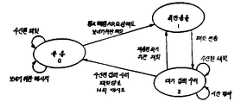
제 2 도에서 그룹(37)은 어나운서(37a)와 리스너(37b,37c) 및 리스너(40)를 갖추고 있고, 그룹(38)은 어나운서(38a)와 리스너(38b,38c) 및 리스너(40)를 갖추고 있다. 제 2 도는 하나의 셀[셀(40)]이 2개의 그룹에서 리스너로 되는 것을 나타낸다. 만일 어나운서(37a)가 광스위치기능을 갖는다면, 그 어나운서는 셀(37b,37c,40)을 통해서 광을 제어하고, 이와 마찬가지로 어나운서(38a)에 관계된 스위치는 셀(37b,37c,40)을통해서 광을 제어할 수 있게 된다.In FIG. 2, group 37 has announcer 37a,
제 3 도에서 그룹(42)은 어나운서(44,45)와 리스너(46,47)로 구성되고, 그룹(43)은 그 그룹(43)에 대한 리스너인 셀(44)을 그룹과 공유하는데, 그룹(41)은 그룹(42)과 셀(47)을 공유하고, 셀(47)은 예컨대 그룹(41)의 리스너(48)에 어나운스할 수 있는 그룹(41)에 대한 어나운서이다. 셀(47)은 또한 그룹(42)에 대한 리스너로서 동작한다. 도시된 바와 같이 하나의 셀이 하나의 그룹에 대해서는 어나운서로 되면서 다른 하나의 그룹에 대해서는 리스너로 된다(셀은 후에 설명하겠지만 이들 기능을 수행하도록 프로그램된다). 그러나 하나의 셀이 하나 이상의 그룹에 대해 어나운스할 수 없다.[본 실시예에서는 각 셀은 3쌍의 입/출력선 및 선택선을 갖추고, 각 쌍은 일종의 수단을 공유한다. 그 선은 공유된 수단이 서로 상충되지 않도록 하는데 필요한 몇몇 기능을 위해 독립적으로 사용된다. 다른 기능에서는 그 선들은 쌍으로서 사용되고 본 예에서는 셀(27)로부터의 한쌍의 리이드가 광스위치에 결합되고, 다른 쌍은 어나운서셀(27)로부터의 통신을 위해 사용된다]In FIG. 3, the group 42 consists of the announcers 44 and 45 and the
서브챈널 : 제 4 도에서 제 1 복수의 셀은 트위스트된 쌍(50 ; 복수의 셀은 C, 어나운서는 A, 리스너는 L로서 도시되었다)과 같은 공통매체를 통해 전송하는 것으로 도시되었다. 이것[예컨대, 트위스트된 쌍(50)]은 서브챈널, 즉 동일한 매체상으로 다른 것과 통신하는 일련의 셀로서 정의된다. 셀(49)과 같은 서브챈널의 요소에 의한 동시통신은 트위스트된 쌍(50) 이상의 서브챈널의 모든 요소에 의해 청취된다.Subchannel: In FIG. 4, the first plurality of cells is shown to be transmitted over a common medium such as a twisted pair (50; plurality of cells are shown as C, announcer as A, listener as L). This (e.g., twisted pair 50) is defined as a subchannel, ie a series of cells in communication with one another on the same medium. Simultaneous communication by subchannel elements such as cell 49 is listened to by all elements of the subchannel above the
챈널 : 챈널은 2개의 서브챈널 또는 동일한 매체를 사용하여 통신하는 모든 셀들인 많은 서브챈널을 포함하고 있다. 제 4 도에서 또 다른 복수의 셀들은 또 다른 서브챈널을 형성하는 트스위트된 쌍(52)에 결합된 것으로 도시되어 있다. 셀(56)(57)이 트스위트된 쌍(72)을 통해서 다른 것과 통신하는 것을 가정하면, 그들은 여전히 또 다른 서브챈널을 형성하게 된다. 트스위트된 쌍(50,52,72)에 관련된 셀은 하나의 챈널을 포함하고 있는데, 이 트스위트된 쌍(50,52,72)은 제 2 챈널(52)로부터 멀리 떨어진 하나의 서브챈널(50)을 갖춘 하나의 연속적인 트스위트된 쌍이고, 서브챈널사이의 통신은 셀(56,57)사이를 달리는 트스위트된 쌍(72)부분상에서 이뤄진다. 이 경우 셀(56)(57)은 그들에게 무언가 추가로 다른 기능(예컨대, 어나운서나 리스너)을 제공하는 리피터로서 할당된다.Channels: A channel contains two subchannels, or many subchannels, all cells that communicate using the same medium. In FIG. 4 another plurality of cells is shown as coupled to a twisted pair 52 forming another subchannel. Assuming cells 56 and 57 communicate with each other over the
제 4 도에 도시된 그룹(55)은 2개의 다른 서브챈널에 어나운서와 리스너를 포함하고 있고, 그룹(75)은 하나의 서브챈널(51)과 서브챈널(52)상에 어나운서를 포함하고 있는데, 서브챈널은 그들의 사용매체가 다르기 때문에 동일한 챈널이 아니다.The group 55 shown in FIG. 4 includes announcers and listeners in two different subchannels, and the group 75 includes announcers on one
관문 : 관문(gateway)은 2개의 다른 매체로부터 패킷을 독출하여 그들을 다시 동시통신한다. 셀은 관문으로 된다. 챈널사이의 통신은 관문(54)을 통해서 이루어진다.Gateway: A gateway reads packets from two different media and communicates them again. The cell becomes the gateway. Communication between channels is through the
제 4 도에서 셀(58)을 포함하는 추가적인 서브챈널은 또 다른 매체(51), 예컨대 공통전력선에 결합된다. 셀(58)은 트스위트된 쌍(52)과의 통시전환시에 도시된 바와 같이 챈널관문(54)에 접속된다. 관문(54)는 어나운서나 리스너기능을 수행하는데 필요하지 않고, 2개의 다른 매체사이의 통신을 제공하는 챈널게이트기능만을 수행한다.In FIG. 4 an additional subchannel comprising cell 58 is coupled to another medium 51, for example a common power line. The cell 58 is connected to the
서브네트워크 : 서브네트워크는 동일한 시스템식별번호(시스템 ID)를 갖는 모든 셀들을 포함한다. 예를 들어 하나의 패밀리홈(family home)내의 모든 셀들은 동일한 시스템 ID를 갖는다. 그러므로 제 4 도의 챈널들은 동일한 시스템 ID 를 공유하는 동일한 서브시스템의 일부분으로 된다.Subnetwork: A subnetwork includes all cells having the same system identification number (system ID). For example, all cells in one family home have the same system ID. Therefore, the channels in FIG. 4 are part of the same subsystem sharing the same system ID.
풀네트워크 : 풀네트워크(full network)는 각각 다른 시스템 ID를 갖는 복수의 서브시스템을 포함한다. 통신프로세서는 서브네트워크사이의 패킷교환에 사용된다. 통신 프로세서는 그들의 시스템 ID의 어드레스 및 다른 정보를 변화시키는 패킷을 중계한다. 2개의 팩토리빌딩은 각각 그들 소유의 시스템 ID를 갖지만, 그 2개사이의 제어는 시스템 ID를 변화시킴으로써 사용된다(네트워크란 단어는 본 명세서에서는 아주 일반적인 의미로 사용된다. 그러므로 본 란에서 정의된 풀네트워크와는 다른 것이다).Full network: A full network includes a plurality of subsystems, each with a different system ID. The communication processor is used for packet exchange between subnetworks. The communication processor relays packets that change the address and other information of their system ID. The two factory buildings each have their own system ID, but the control between the two is used by changing the system ID (the word network is used in a very general sense here. Therefore, the pool defined in this section) Different from the network).
후에 사용되는 다른 용어는 :Other terms used after:
프로브패킷 : 패킷은 네트워크를 통해서 전송되는 루팅정보를 누산하여 한꺼번에 보냄으로써 발송된다.Probe packet: Packets are sent by accumulating routing information sent over the network and sending them all at once.
그룹화 디바이스 : 셀사이의 선로결정과 그룹에 셀할당, 그룹요소에 기능할당을 제어하는 디바이스Grouping device: A device that controls line determination between cells, cell assignment to groups, and function assignment to group elements.
접속 : 2개의 그 이상의 셀이 동일한 시간에서 동일한 서브챈널상으로 동시통신을 시도하거나 그들의 신호 발생을 시도할때 존재하는 상태.Connection: A state in which two or more cells attempt to communicate simultaneously on the same subchannel or to generate their signals at the same time.
B. 그룹형성B. Group Formation
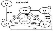
1. 디바이스를 그룹화하여 설치함으로써 그룹에 할당된 셀1. Cells assigned to groups by grouping and installing devices
제 5 도에 도시된 바와 같이 복수의 셀이 전력선으로 통신하기 위해 모두 홈에 접속됨과 더불어 동일한 챈널부분이고, 더욱이 하나의 셀인 어나운서(60)가 리스너(65)와 그룹화되어 있다면, 선(59)과 같은 셀사이의 선은 다른 하나, 예를 들어 서로 통신할 수 있는 어나운서(60) 및 셀(61)과 직접적으로 통신할 수 있는 셀을 나타내는데 사용된다[셀(61,62,63,64)의 경로는 제 5 도에 C로 도시된 바와 같이 설명을 위한 것을 제외하고는 어나운서로 되거나 다른 그룹에서의 리스너로 된다]. 어나운서(60)와 셀(61,62,63)은 모두 서로 통신하게 되므로 그들은 동일한 서브챈널상에 있게 된다. 마찬가지로, 셀(62,64,65,66)은 또다른 서브챈널에 있게 된다(제 5 도에 다른 서브챈널이 도시되어 있다). 중요한 것은 어나운서(60)와 리스너(65)는 제 5 도에 도시된 챈널의 다른 서브챈널에 있고, 예컨대 셀(61,64)을 통하거나 셀(62,64)등을 통해 어나운서(60)로부터 리스너(65)로 메시지가 통과될 수 잇는 선로는 많이 있다는 것이다.As shown in FIG. 5, if a plurality of cells are all connected to a home for communication over a power line, and the announcer 60, which is the same channel part, and more than one cell is grouped with the listener 65, the line 59 Lines between cells such as < RTI ID = 0.0 >) < / RTI > are used to represent the other one, for example the announcer 60, which can communicate with each other, and the cell, which can communicate directly with the cell 61 (cells 61, 62, 63, 64) may be an announcer or listener in another group, except for explanation, as shown by C in FIG. Announcer 60 and cells 61, 62, and 63 are all in communication with each other so that they are on the same subchannel. Likewise, cells 62, 64, 65 and 66 are in another subchannel (other subchannels are shown in FIG. 5). Importantly, the announcer 60 and the listener 65 are in different subchannels of the channel shown in FIG. 5, for example through the cells 61, 64 or through the cells 62, 64, etc. There are a number of tracks through which messages can pass through to the listener 65.
비록, 모든 셀이 하우스의 동일한 전력시스템상에 있더라도 그들은 서로 직접적으로 통신할 수 없다. 예를 들어 어나운서(60)은 홈의 길이를 달리는 긴 길이의 와이어와 로우임피던스버스바의 회로브레이커패널을 통해서 단지 리스너(65)에 결합된 하나의 회로이고, 고주파수의 통신메시지는 비록 셀사이가 물리적으로 서로 닫혀있다 하더라도 그들 사이의 직접통신을 방지하기 위해 그 선로를 통해 충분하게 감쇄되게 된다.Although all cells are on the same power system in the house, they cannot communicate directly with each other. For example, the announcer 60 is a circuit coupled to the listener 65 only through a long wire running through the groove and a circuit breaker panel of a low impedance bus bar, and a high frequency communication message is used between cells. Even if they are physically closed, they are sufficiently attenuated through the line to prevent direct communication between them.
이하의 설명에서, 각 셀이 다른 셀의 동시통신에 방해받지 않고 동시통신할 수 있다고 가정하면, 즉 메시지가 서로 방해받지 않는다면 본 적용의 프로토콜하에서 몇몇 충돌발생의 경우는 해결된다.In the following description, assuming that each cell can communicate simultaneously without being disturbed by the simultaneous communication of other cells, i.e., if the messages are not disturbed from each other, some collision cases are solved under the protocol of the present application.
1실시예에서, 어나운서(60)와 리스너(65)의 그룹은 제 28 도에 도시된 그룹화 디바이스를 사용함으로서 형성된다. 이 그룹의 형성전에 어나운서(60)와 리스너(65)는 통상의 셀이고, 어나운서와 리스너에 할당되지 않는다. 각 그룹화된 디바이스는 제조시에 특정한 48비트의 시스템 ID가 할당되는데(상기 실시예에서는 48비트번호가 사용된다), 본 실시예에서는 셀은 각 그룹화된 디바이스에 포함되고 그 셀의 ID는 시스템 ID로 되게 된다.In one embodiment, the group of announcer 60 and listener 65 is formed by using the grouping device shown in FIG. The announcer 60 and listener 65 are normal cells before this group is formed and are not assigned to the announcer and listener. Each grouped device is assigned a specific 48-bit system ID at the time of manufacture (48-bit number is used in this embodiment). In this embodiment, a cell is included in each grouped device and the ID of the cell is the system ID. It becomes
각 시스템이 독특한 시스템 ID를 갖는다는 것을 확실히 하기 위해, 예를 들어 각 홈은 그 자신의 그룹화된 디바이스를 가지므로 서브네트워크를 위한 이 시스템 ID는 네트워크에 대한 셀 패킷에 사용된다. 본 예에서 그룹화된 디바이스는 셀(60)(65)의 셀 ID를 유용하게 한다(셀 ID를 얻기 위한 여러가지 방법은 후에 설명한다).To ensure that each system has a unique system ID, for example, each home has its own grouped device, so this system ID for the subnetwork is used for cell packets for the network. Devices grouped in this example make the cell IDs of cells 60 and 65 useful (various methods for obtaining cell IDs are described later).
그룹화된 디바이스는 3쌍의 셀(또는 선택된)의 입/출력(I/O)선중 하나를 통해 통신함으로서 셀(60)에 접속되는데, 그 그룹화된 디바이스는 셀(60)의 48비트 ID 번호를 독출한다(셀의 ID를 결정하는 다른 방법은 다음에 설명한다). 그룹화된 디바이스는 상기 실시예에서는 10비트인 랜덤한 비트의 2진수를 발생시키는데, 이 수는 어나운서(60)와 리스너(65)를 포함하는 그룹을 위한 그룹식별번호(또는 그룹어드레스)로서 기능한다. 그룹 디바이스는 다른 그룹 ID에 대해 그 번호가 전에 사용된 그룹 ID인지를 체크하고, 만일 이미 사용된 것이라면 다른 번호를 발생시킨다(하나의 그룹 디바이스는 하나의 홈에 할당된 모든 그룹 ID를 기억하고 있다). 그룹화된 디비아스는 셀(60)을 프로그램하여 그것이 어나운서로서 가능하도록 한다.The grouped devices are connected to the cell 60 by communicating over one of three pairs of cell (or selected) input / output (I / O) lines, the grouped device having the 48-bit ID number of the cell 60. Read (an alternative method of determining the cell ID is described below). The grouped devices generate a random bit of binary, which in this embodiment is 10 bits, which function as a group identification number (or group address) for a group comprising an announcer 60 and a listener 65. do. The group device checks for the other group ID whether the number is the group ID used before, and generates another number if it is already used (one group device remembers all group IDs assigned to one home). ). The grouped divides program the cell 60 so that it is possible as an announcer.
그룹화된 디바이스는 만일 그들이 그 그룹의 번호로서 지정되었다면 메시지를 인식하기 위해 네트워크내의 모든 셀에 필요한 특별한 패킷의 그룹번호를 어나운서(60)를 통해 동시통신한다. 이것은 그 그룹 ID가 사용되지 않았는가를 검사하는 또 다른 방법이다.The grouped devices simultaneously communicate via announcer 60 the group number of the particular packet needed for every cell in the network to recognize the message if they were designated as the number of that group. This is another way to check if the group ID is not used.
그룹화된 디바이스는 셀(65)의 ID 번호를 결정하는데, 이것은 셀(65)이 설치되기 전이라도 그 셀에 그룹 디바이스를 직접 접속하거나 또는 다음에 설명할 다른 방법을 사용함으로써 이루어진다. 셀과 그룹은 ASCII 이름으로 할당된다. 예를 들어 프로치라이트(셀이름)과 익스티어리어 라이트(그룹이름). 이것은 ASCII 이름을 어드레스함으로써 셀 ID와 그룹 ID를 선택하기 위해 사용된다.The grouped device determines the ID number of the cell 65, which is achieved by directly connecting the group device to the cell even before the cell 65 is installed or by using another method described below. Cells and groups are assigned ASCII names. For example, Prolight Light (cell name) and Extreme Light (group name). This is used to select cell ID and group ID by addressing ASCII names.
그룹화된 디바이스는 어나운서(60)를 통해 프로브패킷을 전송한다. 이 프로브패킷은 셀(65)의 ID를 포함하고, 그 패킷은 모든 셀이 패킷을 반복해서 수신하도록 함과 더불어, 셀(65)이 패킷을 인식하도록 하게 된다. 각 셀은 프로브패킷을 반복해서 수신하고, 그 자신의 ID 번호를 반복된 패킷에 추가하게 되는데, 각 셀은 그 패킷을 단지 한번만 반복한다(프로브패킷이 후에 설명하는 바와 같이 한번이상 반복되는 것을 방지하기 위한 메카니즘이다).The grouped device transmits the probe packet through the announcer 60. This probe packet contains the ID of the cell 65, and the packet causes all the cells to receive the packet repeatedly while also allowing the cell 65 to recognize the packet. Each cell repeatedly receives a probe packet and adds its own ID number to the repeated packet, each cell repeating the packet only once (preventing the probe packet from repeating more than once, as described later). Mechanism for doing so).
셀(65)은 가장 가깝거나[셀(62)경유], 예컨대 셀(61)(64)을 경유하는 먼 선로를 포함하는 많은 선로를 통해 프로브패킷을 수신하게 된다. 제 1 프로브패킷이 가장 가까운 선로를 통해 셀(65)에 도착되면[셀(62)을 경유한다면], 셀(65)은 그 프로브패킷이 셀(60)에 의해 전달되고, 셀(62)에 의해 반복되며, 셀(65)용으로 지정되었다는 것을 나타내는 패킷을 수신한다. 그리고, 이 제 1 프로브패킷이 셀(65)에 의해 분배된 후에 다른 프로브패킷이 그 셀(65)에 의해 수신된다.Cell 65 will receive probe packets via many lines that are closest (via cell 62), such as far lines via cells 61 and 64. When the first probe packet arrives at cell 65 via the closest line (via cell 62), cell 65 transmits the probe packet by cell 60 to cell 62. Repeated, receiving a packet indicating that it has been designated for cell 65. Then, after the first probe packet is distributed by the cell 65, another probe packet is received by the cell 65.
셀(65)는 원래의 어나운서(60)로 입력수리를 전송한다. 그 패킷은 프로브패킷[예컨대 셀(62)에 의해 반복된]의 선로를 포함한다. 그 패킷은 셀(62)이 그 패킷을 반복하여 수취가 확실해지도록 한다.Cell 65 sends an input repair to original announcer 60. The packet contains a line of probe packets (eg, repeated by cell 62). The packet causes the cell 62 to repeat the packet to ensure receipt.
어나운서(60)는 셀(65)에 대한 입력수리패킷을 수신한 수, 그것을 셀(62)로 반복함으로써 결정한다. 그룹화된 디바이스는 어나운서(60)를 통해 셀(62)의 특정 ID 번호와 그룹번호 및 그룹에 대한 반복기능이 할당됨과 더불어 셀(62)에 송신되는 메시지를 포함하는 반복할당패킷을 보낸다. 이것에 의해 셀(62)은 어나운서 셀(60,65)을 포함하는 그룹에 대한 모든 패킷을 반복하게 된다. 리스너로서 셀(65)을 지정하는 또 다른 메시지는 셀(62)에 의해 반복된 그룹화된 디바이스의 제어하에 어나운서(60)로부터 보내지게 됨으로써 그룹[셀(65)이 그룹번호로 된다]에 대한 메시지로 기능한다. 그룹화된 디바이스는 멤버셀에 기억된 멤버번호를 멤버에 할당한다.The announcer 60 determines the number of received input repair packets for the cell 65 by repeating it in the cell 62. The grouped device sends a repeating assignment packet through the announcer 60 that includes a message sent to the cell 62 with a specific ID number, a group number, and a repeat function for the group. This causes cell 62 to repeat all packets for the group containing announcer cells 60 and 65. Another message specifying the cell 65 as a listener is sent from the announcer 60 under the control of the grouped devices repeated by the cell 62, thereby causing the group (cell 65 to be a group number) to be sent. Function as a message. The grouped device assigns the member number stored in the member cell to the member.
상술한 그룹정보는 제 8 도에 스텝 또는 블록(68∼72)으로 도시되어 있다. 블록(68)은 프로브패킷[예컨대 셀(60)은 모든 셀에 초기프로브패킷을 전송한다]의 동시통신을 나타내는데, 그 패킷은 행선지셀의 어드레스를 포함한다. 패킷이 네트워크를 통해 전송될때 패킷은 패킷[블록(69)]을 반복시키는 그들 셀의 ID 번호에 축적된다. 블록(70)은 행선지셀[예컨대 셀(65)]로부터 프로브패킷으로의 승인(응답)을 도시해 놓은 것으로, 이 패킷은 처음에 수신된 프로브패킷을 포함하는 리피터의 ID 번호를 반환한다. 리피터할당패킷이 보내짐으로써 어나운서가 각 리피터를 통해 그룹에 대한 패킷을 다시 반복해서 동시통신하는 것이 방지된다. 그리고 마지막으로 블록(72)에 도시된 바와 같이 셀(65)등의 행선지셀이 리스너로서 지정된다.The above-mentioned group information is shown in FIG. 8 by steps or blocks 68 to 72. FIG.
2. 미리 설치된 그룹화된 디바이스에 의해 그룹에 할당된 셀2. Cells assigned to groups by preinstalled grouped devices
미리 설치되는 그룹화된 디바이스의 몇몇 형태가 제 28 도에 도시되어 있다. 하나의 디바이스형태는 제조자가 미리 할당된 셀을 그룹으로 사용하는 것이고, 또 다른 디바이스형태는 미리 설치되기 전의 그룹에 셀을 할당하는데 리테일러(retailer)나 다른 셀벤더(cell vendor)를 사용하는 것이다.Some forms of grouped devices that are preinstalled are shown in FIG. 28. One type of device is a manufacturer using a pre-allocated cell as a group, and another type of device uses a retailer or another cell vendor to assign a cell to a group before being pre-installed.
그룹화된 디바이스는 그룹에 셀을 할당함과 더불어 그 그룹에 대해 셀의 기능을 할당한다. 또한 그 그룹화된 디바이스는 그 셀에 시스템 ID 를 할당한다. 미리 설치되는 그룹화된 디바이스에 의해 할당된 시스템 ID는 특정 시스템 ID를 반드시 필요로 하지 않는다(후에 설치되는 그룹화된 디바이스는 각 시스템에 특정한 시스템 ID를 할당한다).A grouped device assigns a cell to a group, as well as assigning cell functions to that group. The grouped device also assigns a system ID to the cell. The system ID assigned by the pre-installed grouping device does not necessarily require a specific system ID (the grouping device installed later assigns a specific system ID to each system).
시스템 ID를 발생시키기 위해 미리 설치되는 그룹화된 디바이스에 의해 사용되는 하나의 방법은 48비트의 어드레스범위로부터 미리 설치된 시스템 ID 이외의 시스템 ID를 선택하는 것이다. 단 범위 1-1023내의 셀 ID는 그룹 ID와 그룹어드레스로서의 사용이 제외되고, 범위 1024-2047내의 셀 ID는 미리 설치되는 시스템 ID로서의 사용이 제외되게 된다.One method used by pre-installed grouped devices to generate a system ID is to select a system ID other than the pre-installed system ID from a 48-bit address range. However, cell IDs in the range 1-1023 are excluded from use as group IDs and group addresses, while cell IDs in the range from 1024-2047 are excluded from use as system IDs that are pre-installed.
그룹화된 디바이스와 다른 네트워크제어디바이스는 후에 설치되는 시스템 ID와 대응되는 미리 설치되는 시스템 ID를 동일하게 할 필요가 있다. 후에 설치되는 시스템 ID는 셀 ID를 복사하는 것으로 발생되기 때문에 셀 ID는 미리 설치되는 시스템 ID에서 벗어난 범위에 할당되지 않게 된다. 그러므로 범위내의 ID 번호는 셀 ID로서 셀에 할당되지 않는다. 그룹에 미리 할당되어 셋트되어 있는 셀은 제조자에 의해 이용되는데, 제조자에 의해 사용된 미리 설치되는 그룹화된 디바이스의 형태는 셀의 불휘발성 메모리에 적절한 코드로 쓰여짐으로써 그룹에 셀이 할당된다. 사용자는 그러한 일련의 셀을 설치하고, 하나의 서브챈널을 통해 통신하는 일련의 셀이 제공된 미리 설치되는 그룹화된 디바이스에 의한 할당없이 동작시키게 된다.The grouped device and the other network control device need to have the same system ID installed in advance and corresponding system ID installed later. Since the system ID to be installed later is caused by copying the cell ID, the cell ID is not assigned to a range outside of the system ID to be installed in advance. Therefore, ID numbers in the range are not assigned to cells as cell IDs. Cells that are pre-assigned and set in a group are used by the manufacturer, and the type of pre-installed grouped device used by the manufacturer is assigned to the group by writing code appropriate to the cell's nonvolatile memory. The user installs such a series of cells and operates without assignment by a pre-installed grouped device provided with a series of cells communicating over one subchannel.
사용자는 셀이 얻어진 시간이나 그 셀이 설치되기 전의 소정 시간에 그룹에 셀을 할당한다. 상술한 것과 다른 셀은 제조자에 의해 그룹에 할당되지 않으므로 이를 비할당된 셀이라 부른다. 비할당된 셀은 모두 동일한 시스템 ID와, 단지 비할당된 셀에만 사용되는 것 이외의 시스템 ID 번호를 갖는다.The user assigns a cell to a group at the time the cell is obtained or at a predetermined time before the cell is installed. Cells other than those described above are not assigned to groups by the manufacturer and thus are called unallocated cells. Unassigned cells all have the same system ID and system ID numbers other than those used only for unassigned cells.
사용자는 제조자에 의해 사용된 미리 설치되는 그룹화된 디바이스와는 다른 미리 설치되는 그룹화된 디바이스를 사용함으로써 그룹에 일련의 셀을 할당한다.A user assigns a series of cells to a group by using a preinstalled grouped device that is different from the preinstalled grouped device used by the manufacturer.
일반적으로, 그러한 그룹화된 디바이스는 하나의 셀과 동시에 동작하고, 오퍼레이터는 새로운 그룹 ID와 시스템 ID를 발생시키기 위해 그룹화된 디바이스에 명령을 부가하며, 그때 각 셀은 디바이스에 접속되게 된다. 오퍼레이트는 셀이 그룹화된 디바이스에 접속된 동안 그룹에 셀을 할당하기 위해 그룹화된 디바이스에 명령을 부가한다. 그룹화된 디바이스는 오퍼레이터에 의해 명령된 새로운 그룹 ID와 시스템 ID가 발생될 때까지 동일한 그룹 ID와 시스템 ID를 셀에 할당한다.In general, such grouped devices operate simultaneously with one cell, and the operator adds commands to the grouped devices to generate new group IDs and system IDs, each cell being then connected to the device. The operand adds an instruction to the grouped device to assign the cell to the group while the cell is connected to the grouped device. The grouped device assigns the same group ID and system ID to the cell until a new group ID and system ID commanded by the operator is generated.
사용자는 그러한 일련의 셀을 설치하고, 그것을 하나의 서브챈널을 통해서 일련의 셀이 통신할 수 있게끔, 제공된 후에 설치되는 그룹화된 디바이스의 사용없이 동작시킨다.The user installs such a series of cells and operates it without the use of grouped devices that are installed after being provided so that the series of cells can communicate through one subchannel.
3. 비할당된 셀그룹화와 설치후의 자기할당3. Unallocated cell grouping and self-allocation after installation
비할당된 셀은 그룹을 형성하고, 설치후에는 다음 방법에 따라 그들 스스로 할당한다.Unassigned cells form a group, and after installation they assign themselves by:
그것의 센서입력을 통해 축적된 제 1 어나운서셀은 그룹형성처리를 제어한다. 미리 설치되는 그룹화된 디바이스이외의 시스템 ID 번호범위로부터 랜덤하게 시스템 ID 번호를 선택하게 되는데, 이때 그룹 ID 번호는 그룹의 일원인 소정 셀로부터 응답을 요청하는 패킷에 동시통신된다. 만일 그러한 어떤 응답이 전송셀에 수신되면 또 다른 그룹 ID가 랜덤하게 선택된다. 셀은 이러한 랜덤그룹 ID를 선택하는 처리와 그룹 ID를 발견할 때까지 이미 사용되고 동작되는 시스템에 사용되지 않는 그룹 ID를 지속적으로 검사한다.The first announcer cell accumulated through its sensor input controls the group forming process. A system ID number is randomly selected from a range of system ID numbers other than a grouped device which is installed in advance, wherein the group ID number is simultaneously communicated to a packet requesting a response from a predetermined cell which is a member of a group. If any such response is received at the transmitting cell, another group ID is chosen at random. The cell continually checks for group IDs that are not already used and operated in the system until the process finds these random group IDs and finds the group ID.
비할당된 셀의 부족한 구성정보는 그것이 리스너나 어나운서중 하나로서 기능하도록 팩토리에서 프로그램된다. 만일 비할당된 셀이 어나운서라면 감지출력이 여기되는 동안 기다리게 되고, 그것이 여기되면 셀은 그룹에 어드레스된 패킷을 전송한다.Insufficient configuration information of an unallocated cell is programmed in the factory so that it functions as either a listener or an announcer. If the unassigned cell is an announcer, it waits for the sense output to be excited, and if it is excited, the cell sends a packet addressed to the group.
만일 비할당된 셀이 라스너라면, 패킷에 대한 전력이 상승한 후에 청취하게 된다. 셀은 그룹에 수신되어 스스로 할당된 제 1 패킷으로부터 그룹 ID를 갖는다. 이때 셀은 어나운서셀에 응답을 전송한다. 이 응답은 단지 패킷승인만이 아니고, 패킷이 어나운서에 의해 승인되어야 그 패킷은 그룹에 리스너로서 셀을 확인한다. 이것은 처리중에 방해와 충돌이 있더라도 모든 리스너 검증패킷이 어나운서에 도착하는 것을 보장한다.If the unassigned cell is a listener, it will listen after the power for the packet is raised. The cell has a group ID from the first packet received in the group and assigned itself. At this time, the cell transmits a response to the announcer cell. This response is not just a packet acknowledgment, but a packet must be acknowledged by the announcer to identify the cell as a listener to the group. This ensures that all listener verification packets arrive at the announcer, even if there are interruptions and conflicts during processing.
그룹어나운스먼스트가 전송되는 셀은 입력되는 각 응답으로부터 그룹멤버의 리스트를 만드는데, 이때 그리스너에 그룹멤버번호를 할당하는 각 리스너에 패킷을 보낸다.The cell to which the group announcement is sent creates a list of group members from each incoming response, sending a packet to each listener assigning the group member number to the Greek.
4. 미리 설치된 후의 선존재그룹에 비할당된 셀결합4. Unassigned Cell Combinations to Preexisting Groups After Pre-Installation
비할당된 셀은 존재하는 시스템에 추가되어, 3항에서 이미 설명했던 방법과 비슷한 방법으로 그룹에 할당된다. 리스너는 3항과 동일한 방법에 의해 시스템 및 그룹을 결합시킨다.Unassigned cells are added to existing systems and assigned to groups in a manner similar to that described previously in
상기한 예에서, 어나운서는 센서입력을 통해서 여기될 때가지 대기하게 되고, 비할당된 어나운서는 제 1 센서입력여기나 그것의 제 1 수신된 패킷동안 대기하게 된다. 이 2가지 사건중 하나는 어나운서셀의 다음 동작을 결정한다.In the above example, the announcer waits until it is excited through the sensor input, and the unassigned announcer waits for the first sensor input here or its first received packet. One of these two events determines the next action of the announcer cell.
만일 셀이 우선 여기되면, 그것은 상기한 예와 같이 그룹형성처리를 제어하고, 만일 어나운서셀이 먼저 그룹패킷을 수신하게 되면, 그것은 어나운서로서 그룹을 결합시킨다. 이때 패킷은 그룹에 대한 구성정보(그룹크기, 어나운서번호등)와 그룹멤버번호의 할당을 요청하는 그룹어나운서에 보내진다.If the cell is first excited, it controls the group forming process as in the above example, and if the announcer cell first receives the group packet, it joins the group as an announcer. At this time, the packet is sent to the group announcer requesting the configuration information (group size, announcer number, etc.) and group member number of the group.
C. 그룹화를 위한 셀검증방법C. Cell Verification Method for Grouping
그룹화된 디바이스가 필요한 스텝을 통해서 그룹을 형성하거나 그 그룹에 셀을 추가하기 위해 그 그룹에 추가되는 셀의 ID를 알아야 한다. 이때 셀 ID를 어드레스로 사용하는 그룹화 디바이스는 그룹화처리동안 셀에 명령을 부가한다. 그룹화 디바이스의 사용자가 셀 ID를 사용하는 방법은 이하와 같다. 다음의 예에서 그룹화 디바이스나 다른 제어디바이스의 셀과의 통신능력은 만일 보호처리가 사용된다면 그 보호처리에 의해 제한된다. 보호처리, 즉 통신제한과 비밀정보는 본 발명의 제한요소가 아니다. 다음의 예는 적절한 보호 처리가 없는 것으로 가정한다. 특히, 그룹화 디바이스가 시스템키(시스템 ID와 인코드키)를 갖는 그룹화 디바이스없이 설치된 셀과 통신하는 것은 불가능하다.In order to form a group or add a cell to the group, the grouped device needs to know the ID of the cell added to the group. At this time, the grouping device using the cell ID as an address adds a command to the cell during the grouping process. The user of the grouping device uses the cell ID as follows. In the following example, the ability to communicate with the cells of a grouping device or other control device is limited by its protection if protection is used. Protective processing, i.e., communication restrictions and confidential information, is not a limiting factor of the present invention. The following example assumes no proper protection. In particular, it is not possible for a grouping device to communicate with a cell installed without a grouping device having a system key (system ID and encode key).
1. 셀에 직접 접속1. Direct access to the cell
그룹화 디바이스는 셀패키지의 I/O선에 접속되고, 이때 그것의 ID를 요청하는 셀에 메시지를 보낸다. 물리적 접속은 셀이 설치되기 전이나 후에 셀의 ID를 발견하는데 사용될 수 있다. 공지의 수단(예컨대 퓨즈나 프로그램된 디스에이블명령)을 사용하여 사용자는 시스템의 보호를 유지하기 위해 셀에 설치된 이러한 기능을 디스에이블할 수 있다.The grouping device is connected to the I / O line of the cell package, which then sends a message to the cell requesting its ID. The physical connection can be used to discover the cell's ID before or after the cell is installed. Using known means (such as fuses or programmed disable commands), the user can disable these functions installed in the cell to maintain the protection of the system.
2. 특별한 핀을 통한 셀의 선택2. Selection of cells via special pins
사용자는 그룹화 디바이스나 다른 몇몇 선택디바이스를 사용하여 선택기능을 제공하도록 지정된 셀입력핀을 여기시킴으로써 셀을 물리적으로 선택하게 된다. 그룹화 디바이스는 통상의 통신챈널을 통해서 셀과 통인하여 그들의 ID로 응답하는 모든 선택된 셀을 요청하는 메시지를 동시통신한다. 단지 하나의 셀이 선택되면 단지 그 셀만이 요청에 대해 응답하게 된다. 또한 이 경우에도 시스템을 보호하기 위한 물건을 사용자가 디스에이블하기 위한 수단이 제공될 수 있다.The user physically selects a cell by using a grouping device or some other selection device to excite a cell input pin designated to provide a selection function. The grouping device concurrently communicates messages requesting all selected cells that respond with their IDs through the normal communication channel. If only one cell is selected, only that cell will respond to the request. Also in this case, a means for the user to disable an object for protecting the system may be provided.
3. 미리 그룹화된 셀의 모든 이름을 질문3. Ask all names of pregrouped cells
셀에 미리 할당된 ASCII 이름이 그룹과 셀이라고 가정한다. 본 방법에서는 그룹화 디바이스는 그들의 그룹 및 셀이름(ASCII 이름)을 리포트하기 위한 시스템내의 모든 셀을 질문한다. 사용자는 그룹화 디바이스를 사용함으로써 그룹이름의 리스트전체를 스크롤한다. 사용자는 목적하는 셀이 포함되어 있는 그룹의 이름을 선택한다. 그룹화 디바이스는 그룹에 있는 모든 셀의 이름과 그들의 할당된 작업(어나운서, 리스너, 리피터)을 디스플레이한다. 사용자는 목적하는 셀이라고 믿어지는 셀의 이름을 선택한다.Assume that the ASCII names preassigned to a cell are a group and a cell. In this method, the grouping device queries all cells in the system to report their group and cell name (ASCII name). The user scrolls through the list of group names by using the grouping device. The user selects the name of the group containing the desired cell. The grouping device displays the names of all the cells in the group and their assigned tasks (announcers, listeners, repeaters). The user selects the name of the cell that is believed to be the desired cell.
만일 선택된 셀이 어나운서이면, 그룹화 디바이스는 그것의 입력을 여기시켜 어나운서를 활성화시킴으로서 사용자는를 보조한다. 예를 들어 만일 셀이 광스위치에 부착되어 있다면, 사용자는 그 스위치는 턴은 또는 턴오프하게 되고, 셀은 그룹에 어나운스먼트 패킷을 보내며, 그룹화 디바이스는 통신채널을 청취하여 그룹 및 멤버번호나 다른 부착된 어나운서의 코드를 알아낸다.If the selected cell is an announcer, the grouping device assists the user by activating the announcer by exciting its input. For example, if a cell is attached to an optical switch, the user turns the switch on or off, the cell sends an announcement packet to the group, and the grouping device listens to the communication channel to listen for the group and member number. Or the code of another attached announcer.
만일, 선택된 셀이 리스너셀이면, 그룹화 디바이스는 셀에 패킷을 보내어(어드레싱을 위한 그룹과 멤버번호를 사용) 그것의 출력을 토글하기 위해 명령한다. 예를 들어 셀이 광을 제어한다면 그 광은 온되거나 오프되게 된다. 따라서 사용자는 그가 선택한 셀이 옳은 것인지를 검사할 수 있게 된다.If the selected cell is a listener cell, the grouping device sends a packet to the cell (using the group and member number for addressing) and instructs to toggle its output. For example, if a cell controls the light, the light is turned on or off. Thus, the user can check whether the cell he selected is correct.
그룹화 디바이스는 그것의 셀 ID를 반환하기 위한 목적 셀을 위한 명령을 가지고 목적셀에 패킷(어드레싱을 위한 그룹과 멤버번호사용)을 보낸다. 그룹화 디바이스는 목적 ID를 알아내어 그룹할당처리를 실행할 수 있게 된다. 이름 질문은 셀이 설치되기 전이나 그 후에 셀의 ID를 알아내는데 사용된다.The grouping device sends a packet (using group and member number for addressing) to the destination cell with an instruction for the destination cell to return its cell ID. The grouping device can find out the destination ID and execute the group assignment process. The name query is used to find out the cell's ID before or after the cell is installed.
4. 그룹여기4. GroupClick here
본 발명은 그룹과 셀의 ASCII 이름이 할당되어 있는 네트워크에 사용된다 사용자는 그룹화 디바이스에 다음 그룹어나운스먼트동안 기다리라는 명령을 부가하고, 이때 관련된 그룹의 어나운서를 여기시킨다. 예를 들어 만일 어나운서가 광스위치라면, 사용자는 스위치를 전환하게 된다. 그리고 이때 그룹화 디바이스는 어나운스먼트패킷을 청취하고 그것으로부터 그룹 ID를 추출한다.The invention is used in a network where the ASCII names of groups and cells are assigned. The user adds a command to the grouping device to wait for the next group announcement, which excites the announcer of the group concerned. For example, if the announcer is an optical switch, the user switches the switch. The grouping device then listens to the announcement packet and extracts the group ID from it.
사용자는 그룹화 디바이스를 통해 그들의 출력을 토글시키기 위해 그들에 명령하는 모든 그룹리스너에 패킷을 보냄으로써 소정 그룹에 대한 그룹 ID를 검색한다. 그리고 사용자는 리스너셀의 동작(예컨대 그룹이 광제어를 구성한다면 광출력)을 관찰함으로써 소정 그룹을 검사한다.The user retrieves the group ID for a given group by sending a packet to all group listeners instructing them to toggle their output through the grouping device. The user then inspects a given group by observing the operation of the listener cell (e.g., the light output if the group constitutes light control).
그룹 ID를 사용하여, 그룹화 디바이스는 관련된 셀이 발견될 때까지 그것의 셀이름으로 응답하도록 각 셀에 요청하는 그룹에 패킷을 동시통인한다. 사용자는 그 이름과 셀 ID를 알고 있는 그룹화 디바이스를 선택하여 그룹할당처리를 실행한다.Using the group ID, the grouping device simultaneously passes the packet to the group requesting each cell to respond with its cell name until an associated cell is found. The user selects a grouping device that knows its name and cell ID to execute group assignment processing.
만일 사용자가 선택하면, 셀의 ID는 그룹화과정의 처리전에 검색되고, 다음의 처리는 목적셀에 대한 ID 검사에 사용된다.If the user selects, the cell's ID is retrieved before the grouping process, and the following process is used to check the ID of the target cell.
만일 선택된 셀이 어나운서라면, 그룹화 디바이스는 어나운서의 입력을 여기시켜 어나운서를 활성화함으로써 사용자를 보조한다. 예를 들어, 셀이 광스위치에 부착되어 있다면 사용자는 스위치를 온,오프시키게 되고, 이때 그룹화 디바이스는 그룹어드레스와 셀의 멤버번호를 알아낼 수 있게 된다.If the selected cell is an announcer, the grouping device assists the user by activating the announcer by exciting the input of the announcer. For example, if a cell is attached to an optical switch, the user turns the switch on and off, and the grouping device can find out the group address and the member number of the cell.
만일 선택된 셀이 리스너라면 그룹화 디바이스는 셀에 그것의 출력을 토글시키기 위해 명령하는 패킷을 보낸다(어드레싱을 위한 그룹화 멤버번호사용). 예를 들어 셀이 광을 제어한다면, 그 광은 온,오프되게 된다. 따라서 사용자는 올바르게 셀이 선택되었는가를 검사할 수 있게 된다.If the selected cell is a listener, the grouping device sends a packet instructing the cell to toggle its output (using the grouping member number for addressing). For example, if a cell controls light, the light is turned on and off. Thus, the user can check whether the cell is correctly selected.
5. 어나운서여기5. AnnouncerClick here
본 방법은 그룹과 셀의 ASCII 이름은 할당되어 있지 않고, 어나운서와 리스너는 할당되어 있는 네트워크에 사용된다. 그룹화 디바이스는 다음번에 여기되는 그것의 ID를 포함하는 패킷을 동시통신하기 위해 네트워크내의 모든 셀에 패킷을 보내서 각 어나운서에 명령을 부가한다. 이때 그룹화 디바이스는 그것의 감지된 디바이스를 활성화하여 어나운서를 여기시킴으로써 사용자를 보조한다. 예를 들어 광스위치어나운서에 대한 광스위치를 턴온시킨다. 사용자는 단지 하나의 어나운서만을 여기시키게 되므로 그룹화 디바이스는 단지 하나의 패킷만을 셀 ID로서 수신한다.In this method, the ASCII names of groups and cells are not assigned, and the announcer and listener are used for the assigned network. The grouping device adds a command to each announcer by sending a packet to all cells in the network to simultaneously communicate a packet containing its ID which is next excited. The grouping device then assists the user by activating its sensed device to excite the announcer. For example, turn on the optical switch for the optical switch announcer. The user will only excite one announcer so that the grouping device receives only one packet as the cell ID.
또 다른 어나운서셀은 동일한 시간에 여기된다. 누군가에 의해 광스위치가 전환되거나 온도센서가 검출되면, 사용자는 수신된 ID가 올바른 셀에 대한 것인가를 검사하게 되는데, 셀 ID가 올바른 것인가를 검사하기 위해, 사용자는 제 2 시간에 대한 어나운서여기처리를 통하여 동일한 결과가 발생되는가를 검사한다.Another announcer cell is excited at the same time. When the optical switch is switched by someone or the temperature sensor is detected, the user checks whether the received ID is for the correct cell, and to check if the cell ID is correct, the user is known for the second time. The process checks whether the same result is generated.
6. 리스너토글6. Listener Toggle
본 방법은 그룹과 셀이름이 할당되어 있지 않은 네트워크에 사용된다. 그룹화 디바이스는 그들의 ID로 응답하는 리스너인 셀을 묻는 패킷을 동시통신한다. 그룹화 디바이스는 가능한 셀 ID 부분으로 응답을 제한하기 위해 ID 비트 마스크를 포함하는 패킷을 응답하는 셀의 번호를 제한할 필요가 있다. 그룹화 디바이스가 리스너 ID의 리스트를 표시할때 사용자는 각 리스너를 토글시키게 되는 바, 이 리스너셀에 의해 출력은 턴온 및 턴오프되게 된다. 사용자는 그것의 출력이 토글하는 목적셀을 관찰할 때까지 리스너셀의 리스트를 통해 계속하게 된다. 이때 사용자는 그룹화 디바이스에 셀을 일치시키고, 그것을 그룹화 동작으로 처리할 수 있게 된다.This method is used for networks that do not have group and cell names assigned. The grouping devices concurrently communicate packets asking for cells which are listeners responding with their IDs. The grouping device needs to limit the number of cells that respond to the packet containing the ID bit mask to limit the response to possible cell ID parts. When the grouping device displays a list of listener IDs, the user toggles each listener, which causes the output to be turned on and off. The user continues through the list of listener cells until he observes the destination cell whose output toggles. At this time, the user can match a cell with the grouping device and process it as a grouping operation.
D. 패킷포맷D. Packet Format
각 패킷은 수많은 필드를 포함하는 셀에 의해 전송된다. 예를 들어, 포맷은 제 6 도에 도시된 그룹어나운스먼트용으로 사용된다. 다른 패킷포맷은 부록 A에 나타냈다. 프리앰블(preamble)로 시작되는 각 패킷은 수신셀의 입력회로(비트동기)를 동기화하는데 사용된다. 본 실시예에 사용된 특별한 프리앰블코드는 6 대 3 결합코드(제 9 도)의 부분으로서 설명된다. 6비트의 플래그 필드는 각 패킷으로 시작되고 끝난다. 플래그필드코드도 또한 제 9 도에 설명되었다.Each packet is sent by a cell containing a number of fields. For example, the format is used for the group announcement shown in FIG. Other packet formats are shown in Appendix A. Each packet beginning with a preamble is used to synchronize the input circuit (bit synchronization) of the receiving cell. The special preamble code used in this embodiment is described as part of a 6 to 3 combined code (FIG. 9). The 6-bit flag field starts and ends with each packet. The flag field code is also described in FIG.
상술한 바와 같이, 각 셀은 전체 패킷을 독출하고, 회선쟁탈타이머필드를 제외한 패킷상의 순환 여유코드(CRC)를 계산하며, 수신된 패킷의 그 CRC 필드 결과를 비교한다. 제 12 도의 ALU(102)는 패킷 CRC와 중간 결과를 계산하기 위한, CRC 레지스터(130)를 계산하기 위한 하드웨어이다. 만일, 패킷 CRC가 입력되는 패킷을 검사할 수 없다면 패킷은 방출된다. 패킷 CRC 필드는 계산된 바와 같이 16비트이고, 그때 제 9 도의 인코딩을 사용하는 3 대 6 코드로 전송하기 위한 24비트필드로 변환된다(본 단에서 패킷 필드를 설명한 나머지는 제 9 도의 3 대 6결합코드로 인코딩하기에 앞서 필드길이로 설명된다). 본 실시예에서 CRC는 CCITT 표준 알고리즘(X16+X12+X5+1)이다.As described above, each cell reads out the entire packet, calculates a cyclic margin code (CRC) on the packet excluding the contention timer field, and compares the result of the CRC field of the received packet. The ALU 102 of FIG. 12 is hardware for calculating the CRC register 130 for calculating packet CRC and intermediate results. If the packet CRC cannot check the incoming packet, the packet is released. The packet CRC field is 16 bits as calculated and then converted to a 24-bit field for transmission in a 3 to 6 code using the encoding of FIG. 9 (the rest of the packet fields described in this section are 3 to 6 in FIG. 9). It is described by the field length before encoding to the join code). In this embodiment, the CRC is the CCITT standard algorithm (X16 + X12 + X5 +1).
시스템 ID는 최근에는 32비트필드이고, 48비트시스템 ID중 다른 16비트는 CRC 계산에 포함되며, 패킷(제 29 도)의 f 부분으로서 전송되지는 않는다.The system ID is a 32-bit field recently, the other 16 bits of the 48-bit system ID are included in the CRC calculation and are not transmitted as part of the packet (Fig. 29).
링크어드레스필드는 48비트필드이다. 이 필드가 모드 0일때 패킷은 모든 셀에 의해 작용되는 광대역통신시스템으로서 해석된다. 예를 들어 프로브패킷이 링크어드레스에 대해 모두 0이고, 그룹어드레스가 그링크어드레스내에 포함된다. 그룹어드레스용 제138비트는 0이고 나머지 10비트는 그룹어드레스를 포함한다(210어드레스는 그룹용으로 보존되므로, 셀 ID 번호는 앞에서 설명한 1024에서 248까지 범위의 팩토리에서 할당된다). 몇몇 경우에 어드레스는 개개의 셀어드레스로 된다(예를 들어 셀이 리피터나 리스너의 작업에 할당되어 있을 때).The link address field is a 48 bit field. When this field is
회선쟁탈타이머는 10비트의 타이머필드의 검색에 사용되는 추가적인 CRC 필드(다른 체크합)용 6비트를 갖는 10비트필드이다. 패킷을 반복하는 각 셀은 만일 그 셀이 패킷을 전송하기 위해 대기해야 한다면 이 필드에서 동작한다. 또 만일 하나의 셀은 패킷을 전송하기 위해 대기상태에 있을 때까지 패킷이 다른 셀에 의해 전송되고 있다면, 그것이 대기하는 시간은 회선쟁탈타이머필드를 역카운트함으로써 지시된다. 이 필드가 역카운트되는 속도는 셀에 프로그램될 수 있고, 이 속도가 네트워크의 기능형태이다. 필드는 네트워크형태에 의해 선택되는 상수로 시작된다. 패킷을 반복하는 각 셀은 패킷이 수신되는 시점에서의 필드에서 번호를 역카운트한다. 그러므로 만일 패킷이 4번 반복되고 각 4개의 셀이 전송을 위해 대기하고 있다면, 접속필드에서의 수는 상수(예컨대, 모두 1)로부터 뺀 대기시간의 합을 반영하게 된다. 회선쟁탈타이머필드가 모두 0에 도달하면, 패킷을 전송하기 위해 대기하여 그것을 전송하는 대신에 그 패킷을 방출한다. 이것은 이전의 패킷을 도착되는 새로운 패킷으로부터 보호되기 위한 것이다.The contention timer is a 10-bit field with 6 bits for an additional CRC field (another check sum) used for searching for a 10-bit timer field. Each cell repeating the packet operates in this field if the cell has to wait to transmit the packet. Also, if a cell is being transmitted by another cell until one cell is waiting to send the packet, the time it waits is indicated by decounting the contention timer field. The rate at which this field is reverse counted can be programmed into the cell, which is a function of the network. The field begins with a constant selected by the network type. Each cell repeating the packet backcounts the number in the field at the time the packet is received. Therefore, if a packet is repeated four times and each of the four cells is waiting for transmission, the number in the connection field will reflect the sum of the wait times minus the constant (eg all 1s). When the contention timer field reaches zero all, it waits to send a packet and emits the packet instead of sending it. This is to protect the previous packet from new packets arriving.
상술한 바와 같이, 회선쟁탈타이머는 6비트 CRC 필드를 소유하고, 회선쟁탈타이머필드가 패킷 CRC에 포함되면, 패킷이 실제적으로 전송될 수 있을 때까지 계산되지 않는다. 이것은 전송전의 가장 최근의 수마이크로초동안 많은 계산을 하기 위해 필요하다. 이러한 문제를 해결하기 위해, 분리 CRC 필드가 회선쟁탈타이머용으로 사용된다. 만약 회선쟁탈타이머가 6비트 CRC에 의해 검색될 수 없다면 그 패킷은 폐기된다.As mentioned above, if the contention timer has a 6-bit CRC field and the contention timer field is included in the packet CRC, it is not calculated until the packet can be actually transmitted. This is necessary to make many calculations for the most recent few microseconds before transmission. To solve this problem, a separate CRC field is used for the contention timer. If the contention timer cannot be retrieved by the 6-bit CRC, the packet is discarded.
호프계수필드는 그것의 목적지에 도달하기 전에 패킷이 갖는 호프나 재전송의 번호를 기억한다. 이 4비트필드는 특정한 패킷에 허용되는 재전송의 최대번호에서 시작되고, 패킷을 반복하는 각 셀에 의해 감소된다.The hop count field stores the number of hops or retransmissions a packet has before it reaches its destination. This 4-bit field starts at the maximum number of retransmissions allowed for a particular packet and is reduced by each cell repeating the packet.
예를 들어, 그룹어나운서에 의해 초기화된 패킷에서 시작하는 호프계수는 그룹의 모든 셀이 도달해야 하는 패킷의 최대 재전송수이다. 이 필드가 모두 0으로 되면, 패킷은 다시 전송되지 않고 셀에 의해 폐기된다. 그러므로 16호프나 재전송을 일반적으로 실행될 때와 같이 제한이 있다.For example, the hop coefficient starting from a packet initialized by a group announcer is the maximum number of retransmissions of a packet that all cells in the group must reach. If all of these fields are zero, the packet is not sent again and is discarded by the cell. Therefore, there are restrictions, such as when 16 hops or retransmissions are normally executed.
링크제어필드는 8비트로 구성됨과 더불어 링크프로토콜을 제공하는데, 이 필드는 프로토콜의 다른 계층에 대한 부분에서 설명한다.The link control field consists of 8 bits and provides the link protocol, which is described in the section on other layers of the protocol.
랜덤/허위 랜덤번호필드는 최초에 패킷을 전송하는 셀에 의해 각 패킷에 대해 발생되는 8비트랜덤번호를 포함한다. 이 번호는 패킷이 반복될때 다시 발생되지 않는다. 이 번호는 제 8 도에서 설명되는 바와 같이 프로브패킷의 반복 동시통신을 제한하기 위해 사용된다. 또한 그것은 전체 패킷이 인코딩되는 인코딩결함에 사용된다.The random / false random number field contains an 8-bit random number generated for each packet by the cell which initially transmits the packet. This number is not generated again when the packet is repeated. This number is used to limit the repetitive simultaneous communication of probe packets as described in FIG. It is also used for encoding defects where the entire packet is encoded.
네트워크제어필드(4비트)는 구성형태나 패킷형태, 예컨대 네트워크제어, 그룹메시지, 프로브메시지등을 지시한다.The network control field (4 bits) indicates a configuration form or a packet form, for example, network control, group message, probe message, or the like.
소오스어드레스필드(가변크기)는 예컨대 패킷을 만드는 셀의 48비트 ID 번호를 포함한다. 프로브패킷에 대해 이 필드는 어나운서의 ID 번호를 포함하고, 승인에 대해 그 필드는 리스너의 ID를 포함하며, 그룹에 어드레스된 패킷에 대해 이 필드는 소오스셀의 그룹멤버번호를 포함한다.The source address field (variable size) contains, for example, the 48-bit ID number of the cell making the packet. For probe packets this field contains the ID number of the announcer, for acknowledgment the field contains the ID of the listener, and for packets addressed to the group this field contains the group member number of the source cell.
행선지리스트를 제 7 도를 참조해서 설명한다.The destination list will be described with reference to FIG.
메시지필드는 길이가 가변적이고, 패킷으로 전송되는 특정한 메시지를 포함한다. 전형적인 메시지는 부록 B에 포함되어 있다. 프로브패킷의 경우에 그 필드는 루팅을 포함한다. 즉 각 셀반복이 이 필드의 ID 번호를 포함한다. 메시지는 그룹이 한번 형성될때 예를 들어 리스너(65)가 광을 온시키도록 하기 위한 어나운서(60)에 의해 사용된다. 인코드필드가 사용될때 인코드된 패킷의 신뢰성있는 조사에 사용되는 16비트를 포함하고, 이 전형적인 패킷부분은 패킷이 반복될때 변화되지 않으며, 잘 알려진 인코드기술이 사용된다.The message field is variable in length and contains a specific message sent in a packet. Typical messages are included in Appendix B. In the case of probe packets, the field contains routing. That is, each cell repetition contains the ID number of this field. The message is used by the announcer 60 to, for example, cause the listener 65 to turn on the light when the group is formed once. When an encoded field is used, it contains 16 bits used for reliable inspection of the encoded packet. This typical packet part is not changed when the packet is repeated, and a well-known encoding technique is used.
제 6 도의 브래킷(99)은 패킷이 반복될때 변화되지 않고 남아 있는 패킷부분을 나타내는데, 이들 필드는 제 8 도에 대한 설명에서와 같이 반복되는 것을 제한하기 위해 사용된다.The
제 6 도의 패킷중 행선지리스트필드가 제 7 도에 도시되어 있다. 행선지리스트는 패킷내의 메시지를 수신하기 위해 지정된 그룹의 멤버번호를 나타내는 4비트필드로 시작된다. 그러므로 패킷은 그룹의 16멤버에 이르기까지 지도된다. 그룹내의 각 멤버의 번호는 이때 뒤이은 8비트필드로 전송된다. 그룹번호는 링크어드레스에 포함되고, 멤버번호는 그룹이 한번 형성될때 메시지를 전송하기 위해 사용되는 어드레스를 형성하는 행선지리스트에 포함된다. 만일 행선지번호가 0이면, 패킷은 그 그룹의 모든 멤버에 어드레스된다. 몇몇 패킷 형태에 대해 이 필드는 수신하는 셀의 ID를 포함한다(부록 A 참조).The destination list field in the packet of FIG. 6 is shown in FIG. The destination list begins with a 4-bit field indicating the member number of the group designated to receive the message in the packet. Therefore, packets are directed up to 16 members of a group. The number of each member in the group is then transmitted in the subsequent 8-bit field. The group number is included in the link address, and the member number is included in the destination list which forms an address used to transmit a message when the group is formed once. If the destination number is zero, the packet is addressed to all members of that group. For some packet types this field contains the ID of the receiving cell (see Appendix A).
E. 특정패킷이 다시 동시통신되는 것을 방지하기 위한 메카니즘E. Mechanisms to Prevent Specific Packets from Being Simultaneously
상술한 바와 같이, 프로브패킷은 그 패킷이 초기에 동시통신된 후, 각 셀에 의해 단지 한번만 반복된다. 특별한 메카니즘은 제일 나중에 반복된 패킷을 셀이 인식할 수 있도록 각 셀에 프로그램되어 있다.As mentioned above, the probe packet is repeated only once by each cell after the packets are initially co-communicated. A special mechanism is programmed in each cell so that the cell can recognize the last repeated packet.
우선, 각 셀이 전송하거나 또는 패킷을 재전송하는 것을 취소하고, 종료플래그에 우선하는 패킷 CRC 필드를 계산한다. 패킷이 반복되는 동안 적어도 호프계수가 변화되므로 새로운 CRC가 필요하게 되고, 그 패킷에 대해 새로운 패킷 CRC가 요구된다. 이 CRC 필드는 이하에서 설명하게 될 CRC 필드와는 다른 것이다.First, each cell cancels the transmission or retransmission of the packet, and calculates a packet CRC field that precedes the end flag. A new CRC is needed because at least the hop coefficient is changed while the packet is being repeated, a new packet CRC is required for that packet. This CRC field is different from the CRC field described below.
반복이 필요한 각 패킷이 수신되면, 제 6 도의 브래킷(99)에 의해 제시된 바와 같이 리피터 CRC 번호는 링크제어의 시작으로부터 행선지리스트의 끝까지 펼쳐진 필드에 대해 계산된다. 셀이 패킷을 다시 동시통신할때 그것은 16비트 리피터 CRC를 기억한다. 따라서 동일한 번호가 미리 기억되지 않았다면 그러한 번호의 리스트는 순환된다. 그러나, 필드(99)에 대해 계산된 결과 순환리스트가 리피터 CRC를 포함하지 않는다면 그 패킷은 반복된다.When each packet that needs to be repeated is received, the repeater CRC number as calculated by
그러므로, 반복이 필요한 각 패킷이 수신되면 CRC는 필드(99)에 대해 계산된다. 이것을 제 8 도의 블록(73a)으로 나타내었다. 이 번호는 블록(73b)으로 나타내어진 셀내에 포함되는 RAM내에 기억된 8번 리스트와 비교되고, 그 번호가 그 기억된 번호중에서 발견되지 않으면 블록(73c)로 나타낸 바와 같이 새로운 리피터 CRC 결과가 기억됨과 더불어 패킷은 반복된다. 한편, 그 번호가 발견되면 그 패킷은 반복되지 않는다. 8번은 순환리스트에 기억된다. 즉 가장 오래된 번호가 폐기되고, 새로운 것이 계산된다.Therefore, the CRC is calculated for
리피터 CRC 계산의 사용은 필드(99)에 관련되고, 순환리스트의 사용에 의해 이미 다시 동시통신된 패킷의 반복을 방지되게 된다. 예를 들어 광을 지속적으로 턴온, 턴오프시키는 것과 같이 어나운서가 동일한 연속메시지를 지속적으로 반복통신하더라도, 패킷은 다르게 나타나는 메시지를 포함하게 되므로 셀은 리피터가 동일한 메시지를 반복통신하도록 지정하게 된다. 이것은 각 이상적인 메시지와 같이 보내진 랜덤번호가 다르기 때문이다. 그렇지만, 셀이 동일한 필드(99 ; 동일한 랜던번호)내에 포함된 동일한 메시지를 수신하는 경우에는 그 메시지가 갖추어진 패킷은 다시 동시통신되지 않는다. 이것은 프로브패킷에 대해서도 부분적으로 사실이다. 따라서 상술한 그룹을 확립하기 위해 동기통신프로브패킷을 네트워크에서 제거한다. 그렇게 하지 않으면 그들은 소정기간 동안 반사되어 네트워크에서 불필요하게 전송된다.The use of repeater CRC calculations is related to
F. 3 대 6 결합코딩F. 3 to 6 combined coding
많은 네트워크에서는 디지탈데이터의 동시전송을 사용하고, 데이터흐름내에 타이밍정보를 싣기 위해 인코딩을 사용한다. 폭넓게 사용되는 인코딩방법의 하나가 맨체스터코딩이다. 맨체스터 또는 다른 코딩을 상술한 패킷을 인코딩하기 위해 사용되고, 코딩은 다음과 같다.Many networks use simultaneous transmission of digital data and encoding to load timing information into the data flow. One widely used encoding method is Manchester coding. Manchester or other coding is used to encode the packet described above, and the coding is as follows.
3 대 6 결합코딩은 본 실시예에서는 전송용 데이터를 인코딩하기 위해 사용된다. 모든 데이터는 4비트 니블로 그룹화되고, 이 각 니블에 대해서는 6비트가 전송된다. 이들 6비트는 항상 3개의 1과 3개의 0으로 된다. 매 6비트에 결합된 3개의 1과 3개의 0의 전송은 셀의 입력회로가 빠르게 동기화되고(비트동기), 성멸한 바와 같이 I/O부와 접속이 빠르게 바이트동기되도록 한다. 또한 한번 동기화되면(헌트모드제외), 비트흐름에 인입되는 천이는 동기유지에 사용된다.Three to six joint coding is used to encode data for transmission in this embodiment. All data is grouped into 4-bit nibbles, with 6 bits transmitted for each of these nibbles. These six bits are always three ones and three zeros. The transmission of three 1s and three zeros, coupled to every six bits, causes the cell's input circuits to be quickly synchronized (bit-synchronized), and as soon as it is destroyed, the I / O section and connections are quickly byte-synchronized. In addition, once synchronized (except for hunt mode), a transition into the bitstream is used to maintain synchronization.
제 9 도의 우측열은 3개의 비트가 1이고 3개의 비트가 0인 6비트패턴의 가능한 결합은 적은 것이고, 왼쪽열에는 6 대 3패턴에 할당된 대응하는 4비트 패턴을 도시해 놓은 것이다. 예를 들어, 셀이 니블 0111을 전송하는 경우에는, 이것은 전송되기 전에 010011로 변환되고, 이와 마찬가지로 0000은 전송되기 전에 011010으로 변환된다. 셀이 6비트패턴을 수신할때는 그것이 대응하는 4비트패턴으로 복귀되도록 그들은 변환시킨다.In the right column of FIG. 9, there are few possible combinations of 6-bit patterns with 3
20개의 3 대 6 패턴과 단지 16개의 가능한 4비트결합이 있다. 그러므로 3 대 6패턴은 4비트 패턴할당에 대응하지 않는다. 3 대 6 패턴 010101은 모든 패킷에 대한 프리앰블로서 사용된고, 모든 패킷에 대한 플래그는 101010이다. 프리앰블과 플래그패턴은 그들이 기본적인 데이터속도로 천이가 반복되기 때문에 데이터동기를 확립하기 위해 입력회로에 사용되기에 아주 좋다. 할당되지 않은 2개의 3 대 6 패턴은 특별한 상태와 명령에 사용될 수 있다.There are 20 three to six patterns and only 16 possible 4-bit combinations. Therefore, three to six patterns do not correspond to 4-bit pattern assignment. The three to six pattern 010101 is used as a preamble for all packets and the flag for all packets is 101010. Preambles and flag patterns are great for use in input circuits to establish data synchronization because they are repeated at the fundamental data rate. Two unassigned three to six patterns can be used for special states and commands.
따라서 셀은 일반적으로 바이트의 전체수로 패킷을 준비하고, 각 니블은 전송전에 6비트패턴이 할당된다. 그리고 이때 프리앰블과 플래그가 추가된다. 4비트패턴으로부터 6비트패턴으로 변환시키거나, 그 역으로 6비트패턴으로부터 4비트패턴으로 변환시키는 회로는 제 14 도 및 제 15 도에 도시되어 있다.Thus, cells typically prepare packets with the total number of bytes, and each nibble is assigned a 6-bit pattern before transmission. At this time, a preamble and a flag are added. Circuits for converting from a 4-bit pattern to a 6-bit pattern, or vice versa, are shown in FIGS. 14 and 15.
Ⅱ. 통신 및 제어 셀II. Communication and control cells
A. 셀의 기판A. Substrate of the Cell
제 10 도에 있어서, 각 셀을 멀티프로세서(100)와 입/출력섹션(107~110), 메모리(115) 및, 구체적으로 발진기(112)와 타이밍 발생기(111)로서 도시된 관련된 타이밍회로로 구성되어 있다.10, each cell is connected to a
도시된 바와 같이 전압펌프(116)는 메모리(115)와 함께 사용된다. 이 셀은 집적회로화된 것이다. 예를 들어 멀티프로세서(100)는 미합중국 특허 4,642,487호에 기재된 게이트배열기술을 사용함에 의해 제조된 것이다. 상기 실시예에서의 셀은 단일 실리콘기판상에 집적회로로서 제 10 도에 도시된 완전한 셀을 형성한 CMOS 기술을 사용한 것이다[멀티프로세서(100)는 비록 설명에서는 4개의 프로세서로 되어 있지만 때때로 싱글로 간주된다].As shown, the
멀티프로세서(100)는 산술논리유니트(102 ; ALU)에 입력을 공급하는 4셋트의 레지스터(101)를 갖춘 적층 방향지워진 프로세서이다. 본 실시예에서는 ALU(102)는 2개의 분리 ALU를 포함하고 있다.
메모리(15)는 반드시 제한이 있는 것은 아니지만 본 실시예에서는 총 64KB의 기억용량을 갖추고 있다. 메모리의 일부분은[ROM코드(115a)]은 명령을 기억하는데 사용되고, 그 메모리의 다른 부분은 통상의 스태틱 메모리셀(다이나믹셀도 사용될 수 있다)을 다수 포함하는 랜덤억세스메모리이며, 그 메모리의 제 3 부분은 전기적으로 소거 및 프로그램이 가능한 ROM(EEPROM ; 115c)으로는 부유게이트를 갖춘 메모리리바이스가 사용되고, 이들 장치는 프로그램하거나 소거하기 위해 고전압(통상의 동작전압보다 더 높은 전압)이 필요로 되는데, 이 고전압은 온-칩(on-chip) 전압펌프(16)로부터 공급된다. ALU(102a)를 통해서 어드레스되는 메모리(115)용 전체어드레스공간을 ALU(102)의 일부분이다.The
ROM(115a)는 본 적용에서 설명된 프로토콜의 여러가지 층을 실행하는데 소용되는 루틴을 기억하게 되고, 또한 EPROM(115c)에 프로그램하기 위해 필요한 루틴을 기억한다. ROM(115a)에 기억되는 셀용의 응용프로그램은 일반적으로 덮인 변수 및 메시지와, 응용변수 및, 상태머신 기술어를 기억하는 여러가지 EEPROM(115c)과 RAM(115b) 및 RAM(115b)에 의해 구동되는 상태머신으로서 작용하는 루틴이다. 셀 ID, 시스템 ID, 통신 및 응용파라미터(예컨대 그룹번호, 멤버번호, 어나운서/리피터/리스너할당)은 EEPROM(115c)에 기억된다. 셀 ID를 기억하는 EEPROM(115c)의 부분은 와이어 보호(wire-protected)되어 있다. 즉, 셀 ID로 한번 프로그램되면 다시 프로그램할 수 없다.The ROM 115a stores routines used to execute various layers of the protocol described in this application, and also stores routines necessary for programming in the EPROM 115c. The application program for cells stored in the ROM 115a is generally driven by various EEPROM 115c, RAM 115b, and RAM 115b which stores the covered variables and messages, application variables, and state machine descriptors. Routine that acts as a state machine. The cell ID, system ID, communication and application parameters (e.g., group number, member number, announcer / repeater / listener assignment) are stored in the EEPROM 115c. The portion of the EEPROM 115c that stores the cell ID is wire-protected. That is, once programmed with the cell ID, it cannot be programmed again.
셀의 입/출력섹션은 4개의 서브섹션(107,108,109,110)을 포함하는데, 이들 서브섹션중 3개(107,108,109)는 그 셀에 접속된 네트워크나 제어 및 감지장치와 통신하기 위한 리이드(103,104,105)를 각각 갖는다. 유지부(110)는 셀의 ID를 결정하는데 사용되는 명령등을 독출하는데 사용될 수 있는 하나의 선택된 (106)을 갖는다. 설명한 바와 같이 서브섹션(110)은 우선적으로 타이밍과 카운팅에 사용된다. 입/출력섹션은 프로세서에 의해 주어진 어드레스공간전체에 어드레스되므로 프로세서를 메모리공간으로서 사용하는 효과가 있다. 각 I/O서브섹션은 각 서브프로세서에 결합될 수 있다. 프로세서(100)의 멀티프로세서구조에 따라 이러한 특징을 프로세서의 연속적인 동작(인터럽트되지 않는)을 제공하게 된다. I/O섹션은 공지의 회로로 제조되는 바, 이는 제 17 도 내지 제 23 도에 도시되어 있다.The input / output section of a cell includes four
제 10 도에 도시된 셀은 발진기 (112)와 타이밍발생기(111)로 구성되는데, 후자는 제 13 도에 도시된 파이플링을 위해 특별히 필요한 타이밍신호를 제공하게 된다. 제 13 도의 위상(1~4)동안에 16mHz 속도로 동작하는 것이 일반적으로 사용되기 때문에 4mHz 마이너명령선회속도가 제공된다. 제 10 도의 셀과 관련된 다른 공지의 선(예컨대 전력선)은 도시되지 않았다.The cell shown in FIG. 10 is comprised of an
B. 프로세서B. Processor
제 12 도에 도시된 프로세서(100)는 2개의 ALU(102a,102b)와 통신하게 되는 복수의 레지스터를 포함한다(다른 프로세서구조는 시스템의 기본이 되는 레지스터뿐만 아니라 다른 ALU 및 메모리배열을 갖는 것이 사용된다. 어드레스 ALU(102a)는 메모리(115)에 대해 어드레스를 부여하고, 데이터 ALU(102b)는 메모리와 I/O 섹션을 위한 데이터를 제공한다. 일반적으로 메모리출력은 레지스터(146)로부터 DBUS(223)를 통해 프로세서레지스터에 결합된다.The
16비트 ABUS(220)는 어드레스 ALU(102a)에 하나의 입력을 제공한다. 베이스포인터레지스터(118)와, 실효어드레스레지스터(119) 및 명령포인터레지스터(120)는 이 버스에 결합된다.16-bit ABUS 220 provides one input to address ALU 102a. The base pointer register 118, the effective address register 119 and the
이들 레지스터를 지시하기 위해 사용된 심볼의 우하측 모서리부분에는 표시 ×4와 함께 화살표가 도시되어 있는데, 이는 예를 들어 베이스포인트레지스터가 4디프(deep)이고, 특히 베이스포인터레지스터가 4개의 16비트레지스터로 구성된 것을 나타내는데 사용된다. 이것은 또한 유효어드레스레지스터 및 명령포인터레지스터에 대해서도 동일하다). BBUS(221)는 레지스터(142)를 통해서 ALU(102)에 12비트입력을 제공하거나, 데이터 ALU(102b)에 8비트입력을 제공한다. 스택레지스터(122)의 최상 4디프, 스택포인터레지스터(123), 복귀포인터레지스터(124) 및, 명령레지스터(125)는 BBUS에 결합된다.In the lower right corner of the symbol used to indicate these registers, an arrow is shown along with the mark x4, for example the base point register is 4 deep, especially the base point register is 4 16 bits. Used to indicate that it is made up of registers. This is also the same for the valid address register and the command pointer register). The BBUS 221 provides a 12 bit input to the ALU 102 via a
CBUS(222)는 레지스터(143)를 통해 ALU(102)에 다른 8비트입력을 제공하는데, 이 CBUS는 명령포인터레지스터(120)와, 스택레지스터(122)의 최상 4디프, 4개의 캐리플래그(129) 및, 4디프 CRC레지스터 및 4디프 넥스트레지스터(131)에 격납된다.The
메모리의 출력에 결합된 MBUS는 레지스터(145b)를 통해 ALU(102b)의 출력으로부터의 데이터를 수신하거나, I/O 섹션(107~110)이나 메모리로부터의 데이터를 수신하게 되는데 이 버스통과레지스터(146)와 DBUS(223)는 레지스터(118,119,120,122,123,124,125,130,131)와 캐리플래그(129)에 입력을 제공한다.The MBUS, coupled to the output of the memory, receives data from the output of the ALU 102b through the
어드레스 ALU(102a)의 출력으로부터 레지스터(120)로 16비트패스(132)가 설치되어 있는데, 여기서, ALU(102b)는 수행 CRC계산을 위한 회로를 포함하고 있다. 이 회로는 양방향성선(133)을 지나 CRC레지스터(130)와 직접 접속된다. 스택레지스터(122)의 최상부는 선(138)을 통해 넥스트레지스터(131)에 접속된다.A 16-bit path 132 is provided from the output of the address ALU 102a to the
이들 선은 레지스터(122)의 내용을 레지스터(131)로 이동시키거나, 레지스터(131)의 내용을 레지스터(122)로 이동시킨다. 최근의 기술에서는 이들 레지스터사이의 양방향적인 (동시)교환은 실행되지 못한다. 메모리의 출력으로부터의 데이터중 4비트는 선(139)을 통해 명령포인터레지스터(120)나 명령레지스터(125)중 어느 하나에 직접적으로 복귀된다.These lines move the contents of
레지스터와 ALU, 메모리 및, 그들 각각의 버스사이의 데이터 및 어드레스의 파이플링[레지스터(141,142,143,144,145)]은 제 3 도에 도시되어 있다.Piping of registers and ALUs, memory, and data and addresses between their respective buses (
스택포인터레지스터(123)중의 어느 하나나, 복귀포인터레지스터(124)중의 어느 하나에서의 데이터는 회로(127)를 통해 직접적으로 증가되거나 감소된다.Data in any of the stack pointer registers 123 or in any of the return pointer registers 124 is increased or decreased directly through the
ALU(102a,102b)는 그들 입력중의 하나를 어느 하나를 출력단자로 통과시킬 수 있고, 증가시킬 수도 있으며, 그들의 입력을 가산할 수도 있다. ALU(102b)는 가산기등에 추가하여 감산, 시프트, 캐리플래그(124)의 셋트(적절할 때), AND, OR, 익스크루시브 OR, 및 보수연산을 실행한다. ALU(102b)는 하나의 스탭으로 넥스트레지스터(131)와 CRC 레지스터(130)의 내용을 결합하고[패스(222)(133)을 통해], 그것을 스택레지스터의 최상부(122)의 내용과 결합하여 CRC 계산에 사용되는 다음번호를 제공할 수 있다. 또한 ALU(102b)는 표준시프트를 수행하여, 하위 4비트와 상위 4비트가 각각 시프트되어 상위 4비트와 하위 4비트로 된 특별한 니블을 제공한다. 또한 ALU(102b)는 F단원에서 설명된 3 대 6 인코딩이나 디코딩을 수행한다.The ALUs 102a and 102b may pass one of their inputs to the output terminal, increase it, or add their inputs. In addition to an adder or the like, the ALU 102b performs subtraction, shifting, carry flag set (if appropriate), AND, OR, exclusive OR, and maintenance operations. The ALU 102b combines the contents of the next register 131 and the
셀용으로 단일 실리콘칩을 사용한 상기 실시예에서는 전원 및 접지와, 모든 I/O된(A,B) 및, 독출전용된 (106)을 위한 다이상에 기본적인 접촉패드가 설치되어 있는데[제12도의 서브섹션(107,108,109,100)], 이들 접촉패드는 패키지되어 기본적인 확장패키지를 부착할때 사용된다.In this embodiment using a single silicon chip for the cell, basic contact pads are provided on the die for power and ground, and for all I / O (A, B) and read only (106).
상기 실시예에 있어서, 기본적인 접촉패드에 추가해서 추가적인 패드가 제 12 도의 ADUS(224)와 MBUS(225)의 접속에 사용된다. 하나의 제어접속패드는 내부메모리를 디저블하는데 사용된다.In this embodiment, in addition to the basic contact pads, additional pads are used to connect ADUS 224 and
즉 제어접속을 활성화함으로써 내부메모리는 디저블되고 ADBUS와 MBUS상의 데이터는 프로세서에 의해 사용된다. 이것은 셀이외의 것이 메모리를 사용할 수 있도록 해주게 된다. 이들 추가접속은 웨이퍼프로브접속이나, 패키지에 핀의 최소수보다 많은 핀을 형성함으로써 억세스된다.In other words, by activating the control connection, the internal memory is deserialized and the data on ADBUS and MBUS is used by the processor. This allows non-cells to use memory. These additional connections are accessed by wafer probe connections or by forming more pins than the minimum number of pins in the package.
셀은 제조시에 초기프로그램이 필요하다. 웨이퍼프로브시간에서 외부메모리는 몇몇의 목적을 위해 사용되는데, 그 하나가 셀검사이고, 다른 것은 제조공정중에 셀 ID를 EEPROM에 쓰기 위한 프로그램을 제공하기 위한 사용이다. 후에 셀에 입력시키게 되는 프로그램이 전원투입과 동시에 셀에 부정되도록 하는 소정의 필요한 EEPROM 구조는 이때 추가되는데, 이때의 초기화 프로그램과 검사프로그램은 공지의 것이다.The cell requires an initial program at the time of manufacture. In wafer probe time, external memory is used for several purposes, one of which is cell inspection, and the other is to provide a program for writing the cell ID into the EEPROM during the manufacturing process. Any necessary EEPROM structure is added at this time so that the program to be inputted to the cell later is turned on at the same time as the power is turned on, and the initialization program and the inspection program at this time are well known.
C. 프로세서의 동작C. Processor Operation
일반적으로, 메모리페치는 ALU(102a)가 메모리어드레스를 공급할때 이루어진다. 메모리어드레스는 베이스어드레스나 레지스터(118)에서의 베이스포인터중 하나로부터 ABUS상의 것이다. 유효어드레스레지스터(119)나 명령포인터레지스터(120)는 스택포인터레지스터(120), 복귀포인터레지스터(124), 스택레지스터의 최상부분(122)이나 명령레지스터(125)로부터 BBU상의 오프셋과 결합된다.Generally, a memory fetch is made when the ALU 102a supplies a memory address. The memory address is on the ABUS from either the base address or the base pointer in register 118. The effective address register 119 or the
가장 일반적인 ALU(102b)에서의 계산을 스택레지스터의 최상부분(122 ; BBUS)과 넥스트레지스터(131)중의 하나나, 명령레지스터(125)중 하나나, 명령레지스터(125)중 하나로부터의 명령부분으로 되는 데이터를 포함한다.The calculation in the most common ALU 102b is performed by one of the top register 122 (BBUS) and the next register 131 of the stack register, one of the command registers 125, or one of the command registers 125. Contains data that becomes
본 실시예에 있어서, 메모리의 출력으로 동작하는 프로세서는 레지스터(146)를 통해서 DBUS(223)에 결합되고, 프로세서는 ALU(102b)의 입력에 직접적으로 결합되어 있는 데이터로 처리하게 된다. 또한 유효레지스터와 같은 몇몇의 다른 레지스터에 의해 실행되는 기능은 다른 레지스터에 의해서도 실행될 수 있는데, 유효레지스터와, 예컨대 CRC 레지스터를 사용하더라도 프로세서의 동작을 향상시킬 수 있게 된다.In this embodiment, the processor operating at the output of the memory is coupled to the
일반적으로, 메모리어드레스상을 위해 베이스포인터는 레지스터(122,123,124,125)중 하나로부터의 오프셋과 함께 레지스터(118,119,120)중 하나에 의해 제공되는데, 어드레스 ALU(120a)가 이들 어드레스를 제공한다. 또한 일반적으로, ALU(120b)는 스택최상부분과 넥스트레지스터의 내용에 따라 동작하는데, 예를 들어 명령레지스터가 ALU(102b)에 중간입력을 공급하는 경우는 제외된다. 특정 어드레싱과 명령은 이후에 설명한다.In general, for memory addresses, a base pointer is provided by one of
D. 다중프로세서동작D. Multiprocessor Operation
프로세서는 제 13 도에서 설명한 다수의 레지스터와 파이플링에 의해 효과적으로 다중프로세서(4개의 프로세서)로 된다.The processor effectively becomes a multiprocessor (four processors) by the multiple registers and piping described in FIG.
상기한 바와 같이, 이와 같은 다중프로세서의 장점은 동작시에 인터럽트가 필요없고, 입,출력신호를 특별히 나눌 필요가 없다는 것이다. 다중프로세서동작은 각 프로세서를 위한 분리 ALU의 사용없이 이루어진다. 본 실시예에서, 경제성은 설계상 2개의 ALU(102a,102b)를 사용함으로써 얻어지지만, 단지 하나의 ALU만이 주어진 소정시간에 동작한다(BBUS는 양 ALU에 입력을 제공한다). 그러므로 본 발명의 다중프로세서동작을 하나의 ALU를 사용하여 얻게 된다.As described above, the advantage of such a multiprocessor is that there is no interruption during operation, and there is no need to specifically divide input and output signals. Multiprocessor operation occurs without the use of a separate ALU for each processor. In this embodiment, economics are obtained by using two ALUs 102a, 102b by design, but only one ALU operates at a given time (BBUS provides input to both ALUs). Therefore, the multiprocessor operation of the present invention is obtained by using one ALU.
처리시스템은 어드레스 ALU와 데이터 ALU 및 메모리를 공유하는 4개의 프리앰블를 갖는다. 기본 마이너주기는 각 프로세서를 위한 4개의 클록주기를 갖는다. ALU는 하나의 클록주기를 갖고 메모리도 하나의 클록주기를 갖는다. 각 프로세서를 위한 마이너주기는 각 프로세서가 각 기본마이너주가 한번으로 메모리와 ALU를 억세스할 수 있도록 하나의 클록주기에 의해 오프셋된다. 각 프로세서는 자신의 레지스터를 갖기 때문에 프로세서는 그것의 통상속도에서 독립적으로 동작할 수 있다. 때문에 시스템은 4개의 프로세서가 병렬로 파이프라인된다.The processing system has four preambles that share an address ALU, a data ALU, and a memory. The default minor cycle has four clock cycles for each processor. The ALU has one clock cycle and the memory has one clock cycle. Minor cycles for each processor are offset by one clock cycle so that each base minor can access memory and ALU once. Each processor has its own register so that the processor can operate independently at its normal speed. As a result, the system pipelines four processors in parallel.
제 12 도의 각 레지스터는 4개의 레지스터그룹중 하나에 관계되고, 각 그룹은 마이크로프로세서동작을 용이하게 함과 더불어 제 13 도의 프로세서(1-4)과 연결되어 있다. 각 4개의 그룹은 하나의 베이스포인터레지스터와 유효어드레스레지스터, 명령포인터레지스터, 스택레지스터의 상부, 스택포인터레지스터, 복귀포인터레지스터, 명령레지스터, CRC 레지스터, 넥스트레지스터 및, 캐리플래그를 포함하고 있는데, 각 관련된 레지스터그룹은 4개의 프로세서중 하나에 대응된다. 각 프로세서는 각각 4개의 클록주기로 되어 있는 마이너주기에서 명령을 실행하게 되는데, 제 1 주기동안에는 프로세서가 ABUS, BBUS 및 CBUS로의 적절한 레지스터를 폐쇄하고, 다음 클록주기에는 ALU가 ABUS, BBUS 및 CBUS의 입력으로부터 발생되는 데이터를 활성화하며, 제 3 클록주기동안 메모리 또는 I/O는 ALU(102a)로부터 입력되는 어드레스와 메모리나 ALU(102b)중 어느 하나에 기억되어 있는 데이터와 함께 활성화되며, 제 4 또는 마지막 클록주기는 DBUS를 통한 ALU(102b)와 메모리로부터 적절한 레지스터로의 결과전송을 금지한다.Each register of FIG. 12 relates to one of four register groups, and each group is connected to the processor 1-4 of FIG. 13 to facilitate microprocessor operation. Each of the four groups contains one base pointer register, a valid address register, a command pointer register, a stack register register, a stack pointer register, a return pointer register, a command register, a CRC register, a next register, and a carry flag. The associated register group corresponds to one of four processors. Each processor executes instructions in a minor cycle of four clock cycles each, during which the processor closes the appropriate registers to ABUS, BBUS, and CBUS, and in the next clock cycle, ALU inputs ABUS, BBUS, and CBUS. Activates data generated from the memory, and during the third clock cycle, the memory or I / O is activated together with the address input from the ALU 102a and the data stored in either the memory or the ALU 102b. The last clock period prohibits the transfer of results from the ALU 102b and memory through the DBUS to the appropriate register.
프로세서는 상술한 시이퀀스를 통한 데이터전파의 웨이브(wave)로서 관할될 수 있다. 각 스텝에서 중간 결과는 일련의 파이프라인레지스터로 클록이 맞춰진다. 이러한 파이프라인레지스터를 사용함으로 각각의 스텝을 시이퀀스로 분리하는 것이 가능하게 되므로, 4개의 스텝을 동시에 실행된다. 4개의 프로세서는 그들이 ALU와 메모리, I/O 및 많은 제어회로를 공유하더라도 다른 것과 방해없이 동작할 수 있다.The processor may be governed as a wave of data propagation through the sequence described above. At each step, the intermediate result is clocked into a series of pipeline registers. By using this pipeline register, it is possible to separate each step into a sequence, so that four steps are executed simultaneously. The four processors can operate seamlessly with others, even if they share ALU and memory, I / O and many control circuits.
파이플링을 포함하는 프로세서의 제어는 제 11 도로부터 분명하게 이해할 수 있다. 각 프로세서를 위해 3비트카운터와 명령레지스터가 있다. 이들은 제 11 도에 카운터(137a~137d)로서 도시되어 있는데, 이 각 카운터는 명령레지스터(125a~125d)중 하나에 각각 연결되어 있다. 각각의 명령레지스터는 DBUS를 통해서 로드되는데, 명령레지스터가 로드되면, 그 명령은 PLA(212)에 결합된다. 이 PLA는 명령은 실행하는데 어느 정도의 주기가 필요하게 되는가를 그 명령으로부터 결정하고, 이때 3비트의 2진수를 로드되어 있는 명령레지스터(125a,125b,125c 또는 125d)와 결합된 카운터(113a,113b,113c 또는 113d)에 로드된다. 예를 들어 명령레지스터(125c)에 CALL명령이 로드되면 2진수 010(3마이너주기를 가리킴)이 카운터(137c)에 로드된다(주어진 명령에 대해 8마이너주기가 사용될 수 있다. 그러나 본 실시예에서는 주어진 소정 명령에 대해 6마이너 주기가 사용된다). 계수값 0은 새로운 명령을 페치하는데 사용된다.The control of the processor, including piping, can be clearly understood from FIG. There is a 3-bit counter and instruction register for each processor. These are shown in Figure 11 as counters 137a-137d, each of which is connected to one of the command registers 125a-125d, respectively. Each command register is loaded via DBUS, which, when loaded, is coupled to the
카운터에서의 계수(예컨대 3비트)와 그것에의 명령(예컨대 12비트)은 15비트입력으로부터 PLA(136)으로의 명령레지스터에 결합된다. 각 4개의 카운터레지스터와 4개의 명령레지스터로부터 이들 15비트입력은 상술한 바와 같이 연속적으로 PLA(136)에 결합되고, 이 PLA의 출력은 프로세서의 동작을 제어한다.The count (e.g. 3 bits) and instructions (e.g. 12 bits) at the counter are coupled to the command register from the 15 bit input to the PLA 136. These 15 bit inputs from each of the four counter registers and the four command registers are continuously coupled to the PLA 136 as described above, and the output of the PLA controls the operation of the processor.
특히 선(213)은 ABUS와 BBUS 및 CBUS상의 데이터흐름을 제어하고, 선(214)은 ALU(102)를 제어하며, 선(215)을 메모리를 제어하고[후에 설명할 서브섹션(107,108,109,220)의 동작], 선(216)은 DBUS상의 데이터흐름을 제어한다. 주어진 명령에 대해 PLA(136)에 의해 공급되는 특정 출력은 본 적용후에 설명하게 될 명령표로부터 이해할 수 있다. 그리고 각 명령을 실행시키기 위해 프로세서가 행하게 되는 처리도 그 명령표에 나타내었다.In particular,
선(213)상의 PLA로부터의 출력은 ABUS와 BBUS 및 CBUS상의 데이터흐름은 제어하고 디바이스에 직접적으로 결합된다. ALU를 제어하는 신호는 선(214)를 통해 ALU에 결합되기 전에 하나의 클록위상지연레지스터(217)를 통해 결합된다. 모든 레지스터(217)는 동일한 속도로 클록이 맞춰져 있기 때문에 레지스터(217)는 설명된 바와 같이 지연기능을 수행하게 된다. 메모리제어에 사용된 PLA(136)로부터의 신호는 메모리에 결합되기 전에 지연레지스터(217)의 2단을 통해 결합되게 된다. 따라서 선(215)상의 신호는 선(213)상의 신호에 관련된 2개의 클록위상동안 지연된다. PLA(136)로부터 송출된 후의 DBUS에 대한 제어신호는 선(216)에 결합되기 전에 3개의 지연레지스터(217)를 통해 결합되므로, 선(213)상의 신호에 관련된 3개의 클록위상이 지연된다. 레지스터(217)는 6mHz 속도에 클록조정되어 있다. 따라서 PLA(136)가 주어진 명령[예컨대, 명령레지스터(125a)의 내용]에 대한 출력제어신호를 공급할때, 제어신호는 제 1 클록위상동안 선(213)에 결합되고, 제 2 클록위상동안 선(214)에 결합되며, 제 3 클록위상동안 선(215)에 결합되고, 제 4 클록위상동안 선(216)에 결합된다. 그리고, 각 명령주기의 제 1 클록위상동안은 카운터(137a)와 명령레지스터(125a)의 내용이 PLA(136)에 결합되고, 제 2 클록위상동안은 카운터(137b)와 명령레지스터(125b)의 내용이 PLA(136)에 결합되며, 제3 및 제 4 클록위상에 대해서도 이상과 같은 방법으로 결합된다.The output from PLA on
명령이 명령레지스터(125a~125b)에 로드되고, 카운터(137a~137b)에 그 각 명령을 실행하기 위해 필요한 마이너주기에 대응하는 2진계수가 로드되었다고 가정한다. 예를 들어, 레지스터(125a)에 CALL 명령이 로드되고, 010이 카운터(137a)에 로드되었다면, 제 1 명령마이너주기동안 010과 CALL에 대한 12비트명령이 PLA(136)에 결합되는 바, 이 15비트입력은 PLA(136)에 공급되므로, 이 PLA(136)로부터는 ABUS와 BBUS, ALU메모리 및, DBUS에 대한 CALL 명령의 제 1 마이너주기(예컨대 4개의 클록위상)을 완료하기 위해 필요한 모든 제어신호를 출력하게 된다. 그 시스템은 파이플링 다중프로세서를 사용하므로 선(213)에 대한 제어신호는 ALU에 입력되는 CALL 명령의 제 1 클록위상동안 다른 제어신호는 파이프라인의 다른 명령동안 ALU와 다른 프로세서의 메모리와 DBUS를 제어한다). 위상2 동안, 137b에 대한 카운터의 계수와 레지스터(125b)의 명령은 PLA(136)에 결합되고, ABUS와 BBUS 및 CBUS를 제어하는 선(213)상의 신호는 제 2 프로세서에 대한 ALU에 입력되어 레지스터(125b)에 포함된 명령을 실행하게 된다. 이러한 제 2 클록위상동안, 선(214)상의 신호는 제 1 프로세서와 ALU를 제어하여 레지스터(125a)에 포함된 제 2 클록위상의 CALL 명령을 실행하기 위해 필요한 기능을 수행한다(지연은 레지스터(217)에 의해 공급된 하나의 위상과 같다). 마찬가지로 제 3 클록위상동안 선(213)상의 신호는 ABUS와 BBUS 및 CBUS를 제어하여 레지스터(125c)에 포함된 명령을 실행하고, 선(215)상의 신호는 메모리를 제어하여 제 1 프로세서 대한 레지스터(125a)내의 명령을 실행한다. 그리고 마지막으로 제 4 클록위상동안, 카운터(137d)의 계수에 따라 레지스터(125d)로부터의 명령이 PLA(136)에 결합된다. 선(213)상의 신호는 ABUS와 BBUS 및 CBUS를 제어하여 제 3 프리앰블에 대한 레지스터(125c)내의 명령을 실행하며, 선(215)에 대한 신호는 메모리를 제어하여 제 2 프로세서에 대한 레지스터(125b)내의 명령을 실행하고, 선(216)상의 신호는 DBUS를 제어하여 제 1 프로세서에 대한 레지스터(125a)내의 명령을 실행한다.It is assumed that instructions are loaded into the instruction registers 125a through 125b, and binary counters corresponding to the minor periods required to execute the respective instructions are loaded into the counters 137a through 137b. For example, if a CALL instruction is loaded into register 125a and 010 is loaded into counter 137a, then the 12-bit instruction for 010 and CALL is coupled to PLA 136 during the first instruction minor period. Since the 15-bit input is fed to the PLA 136, from this PLA 136 all necessary to complete the first minor period (e.g. four clock phases) of the CALL instruction to ABUS and BBUS, ALU memory and DBUS. The control signal is output. The system uses a piped multiprocessor, so that the control signal for
16mHz 클록의 제 4 주기후에 레지스터(137a)내의 계수값은 001로 감소된다. 각 레지스터는 PLA(136)에 의해 포함된 카운터의 내용을 사용한 이후 클록주기를 감소시킨다. 따라서 PLA(136)에의 입력은 레지스터(125a)내의 명령이 동일하더라도 변화되게 되므로, PLA(136)는 CALL 명령의 제 2 마이너주기동안 필요로되는 새로운 출력신호를 공급할 수 있게 된다. 이들 제어신호는 상술한 바와 같이 제어선(213,214,215,216)을 통한 제어를 통해 약간씩 변화되게 된다. 카운터의 계수값이 000에 이르면, 이것은 그것이 프로세서에 보내지는 동안 명령페치로서 인터럽트되게 된다.After the fourth period of the 16 mHz clock, the count value in the register 137a is reduced to 001. Each register decrements the clock period after using the contents of the counter contained by PLA 136. Therefore, the input to PLA 136 is changed even if the instructions in the register 125a are the same, so that the PLA 136 can supply the new output signal required during the second minor period of the CALL instruction. These control signals are slightly changed through the control through the
그러므로 4개의 프로세서 각각은 다른 주기번호를 갖는 각 명령을 동시에 실행하게 된다. 제어신호가 주어진 클록주기동안 가상선(219)에 도달하면 4개의 다른 명령과 4개의 다른 프로세서에 대한 제어신호가 표시되게 된다. 예를 들어 제 1 프로세서와 관련된 제어신호는 제 1 주기동안 선(213)상에 나타내고, 제 2 주기동안은 선(214)상에 나타나며, 제 3 주기동안은 선(215)에 나타나고, 제 4 주기동안은 선(216)상에 나타난다. 제 2 프로세서에 의해 필요로 되는 제어신호는 이하와 같다. 그리고 제3 및 제 4 프로세서에 의해 필요로 되는 것은 제 2 프로세서에 의해 사용된 것 뒷쪽에 있다.Therefore, each of the four processors executes each instruction having a different cycle number at the same time. When the control signal reaches the
제 13 도에 신호의 파이플링이 도시되어 있다. 제 10 도에 도시된 프로세서(100)의 다중프로세서동작은 제 13 도에 4개의 프로세서, 즉 프로세서 1,2,3,4로 도시되어 있다. 레지스터그룹의 각 하나의 프로세서중의 하나와 결합된다. 하나의 명령주기의 4개위상은 제 13 도의 윗쪽에 도시되어 있는 바, 제 13 도에서 레지스터(101)는 ABUS, BBUS 및 CBUS상에 위치하는 명령에서 요청하는 특정 레지스터로부터의 내용을 지시하기 위해 사용된다. 그리고 레지스터는 ABUS상의 118와 119 및 120과, BBUS상의 122와 123, 124 및 125, CBUS상의 120과 122, 129, 130 및 131이다.Piping of the signal is shown in FIG. The multiprocessor operation of
제 1 클록위상동안, 그룹 1레지스터(예컨대, 그들중 2개)에 미리 기억되어 있던 신호는 레지스터로부터 ABUS, BBUS 및 CBUS 게이트되고, 이러한 처리동안 그룹2 레지스터와 관련된 신호는 레지스터(141,142,143)로부터 ALU(102a,102b)로 게이트되며 이와 동시에 신호는 레지스터(145a,145b)로부터 프로세서(3)를 위한 그룹 3레지스터용 메모리로 게이트된다. 그리고 마지막으로 제 1 위상동안 그룹4 레지스터와 연결된 신호는 레지스터(146)로부터 DBUS로 게이트된다. 제 2 주기동안 그룹 1레지스터와 관련된 신호는 ALU로부터 레지스터(145)로 결합되고, 그룹2 레지스터와 관련된 데이터는 메모리에 결합되며, 그룹3 레지스터와 관련된 데이터는 레지스터(146)로부터 DBUS로 결합되고, 그룹4 레지스터에 관련된 신호는 ABUS, BBUS 및 CBUS로 게이트된다.During the first clock phase, the signals previously stored in the
그리고 각 명령주기의 제3 및 제 4 위상동안 이러한 파이플링은 제 13 도에 도시된 바와 같이 계속됨으로써 효과적으로 4개의 프로세서를 제공하게 된다.And during the third and fourth phases of each instruction period, such piping continues as shown in FIG. 13, effectively providing four processors.
E. 프로세서명령E. Processor Instruction
본 섹션에서는 특정 레지스터와 메모리동안에 따른 프로세서의 각 명령을 나타내었다. 소문자는 레지스터의 내용을 나타내었는데 사용된다. 예를 들어, 명령 레지스터의 내용은 ip로서 나타내었다. 레지스터와 플래그는 제 12 도에 그들의 상호관계를 나타내었다.This section shows each instruction of the processor for a particular register and memory. Lowercase letters are used to indicate the contents of a register. For example, the contents of the command register are shown as ip. Registers and flags are shown in FIG. 12 for their interrelationships.
제 12 도 →12th →
식별번호 →Identification number →
ip 명령포인터(14비트) 120ip command pointer (14 bit) 120
(고정된 0000-3FFF의 범위)(Range of fixed 0000-3FFF)
(ROM에 억세스할 수 없는 기본 프로그램)(Basic program with no access to ROM)
ir 명령레지스터(12비트) 125ir command register (12-bit) 125
(ROM에 억세스할 수 없는 기본 프로그램)(Basic program with no access to ROM)
bp 베이스페이지포인터(14비트) 118bp Base Page Pointer (14 bit) 118
(고정된 8000-FFFF의 범위)(Range of fixed 8000-FFFF)
(기록전용)(Record only)
ea 유효어드레스포인터(16비트) 119ea Effective Address Pointer (16 bit) 119
(ROM에 억세스할 수 없는 기본프로그램)(Basic program not accessible to ROM)
sp 데이터스택포인터(8비트) 123sp Data Stack Pointer (8-bit) 123
(bp로부터 포지러프 오프셋, 낮아짐)(Posieroff offset from bp, lowered)
rp 복귀 스택포인터(8비트) 124rp Return stack pointer (8-bit) 124
(bp로부터 포지티브 오프셋, 높아짐)(positive offset from bp, higher)
tos 데이터스택의 최상부(8비트) 122top of tos data stack (8 bit) 122
next 데이터스택의 최상부 아래항(8비트) 131next Bottom term of the data stack (8 bits) 131
crc 스크래치로서 사용되거나 CRC 계산에 사용(8비트) 130Used as a crc scratch or used for CRC calculations (8 bits) 130
flag 캐리플래그(1비트) 129flag carry flag (1-bit) 129
프로세서 ID(2비트)Processor ID (2 bit)
복귀 스택의 최상부 요소는 그것이 물리적으로 RAM에 위치하더라도 레지스터로서 어드레스할 수 있다.The top element of the return stack can address as a register even if it is physically located in RAM.
명령테이블Command table
CALL 1 a a a a a a a a a a a 서브루틴 호출
CALL lib 0 0 0 0 a a a a a a a a 라이브러리 호출
BR 0 0 1 0 1 a a a a a a a 분기
BRZ 0 0 1 0 0 0 a a a a a a TOS==0상의 분기
BRC 0 0 1 0 1 1 a a a a a a 캐리셋트상의 분기
CALL interseg 0 0 1 1 L L L L L L L L 서브루틴CALL
LIT 0 1 0 1 1 f f h b b b b 상수 op TOS
LDC 0 1 0 1 1 1 1 h b b b b 로드상수
ALU 0 1 0 1 0 0 e h f f f f 스택의 최상부와 넥스트
RET 0 1 0 1 0 0 1 1 1 1 0 1 다른 명령으로 복귀하거나 비트셋트
IN,OUT 0 1 0 0 0 w r r r r r r 독출/기록 I/O레지스터IN, OUT 0 1 0 0 0 w r r r r r r Read / write I / O register
LD,ST bp+a 0 1 0 0 1 w a a a a a a 로드, 기억LD, ST bp + a 0 1 0 0 1 w a a a a a a load, memory
LD,ST(bp+p)+a 1 0 0 P P w a a a a a a 로드, 기억LD, ST (bp + p) + a 1 0 0 P P w a a a a a a Load, memory
LDR,STR r 0 1 0 1 0 1 0 w r r r r 로드,기억 CPU regLDR,
각 명령에 대해 동작과 인코딩 및 타이밍을 표준 C언어부호로 아래와 같이 표시한다.For each command, the operation, encoding, and timing are shown in standard C language code as shown below.
CALL call절차CALL call procedure
연산 :calculate :


ip=dest ;ip = dest;
인코딩 :Encoding:
intra-segment :intra-segment:
1aaaa aaaa aaaa1aaaa aaaa aaaa
dest=ip+a+1 ; /

inter-segment :inter-segment:
0011 LLLL LLLL0011 LLLL LLLL
0000 HHHH HHHH0000 HHHH HHHH
dest=H : L ; /

library :library:
0000 aaaa aaaa0000 aaaa aaaa
dest=0×8000+


타이밍timing
CALL type #clocks 특정메모리연산CALL type #clocks Specific memory operation
intra-seg 3intra-seg 3
2
1
0 ir=

interseg 5
4 lobyte(ea)=
3 hibyte(ea)=
2
1
0 ir=

library 4
3
2
1 ip=dest1 ip = dest
0 ir=
BR 항상분기BR Always Quarter
연산 :calculate :
ip=dest :ip = dest:
인코딩 :Encoding:
0010 1aaa aaaa0010 1aaa aaaa
dest=ip+a+1 ; /

타이밍 :timing :
#clocks 특정메모리연산#clocks Specific Memory Operations
1One
0 ir=
BRC 캐리상의 분기Branch of BRC Carry
연산 :calculate :
if(CF)ip=dest ;if (CF) ip = dest;
else ip++ ;else ip ++;
인코딩 :Encoding:
0010 01aa aaaa0010 01aa aaaa
dest=ip+a+1 ; /

타이밍 :timing :
#clocks 특정메모리연산#clocks Specific Memory Operations
1One
0 ir=
oror
0 ir=
BRZ TOS==0상의 분기Branch on BRZ TOS == 0
연산 :calculate :
if(tos==0, tos=next, next=
else ++ ip ;else ++ ip;
인코딩 :Encoding:
0010 00aa aaaa0010 00aa aaaa
dest=ip+a+1 ; /

타이밍 :timing :
#clocks 특정메모리연산#clocks Specific Memory Operations
2 1 tos=next ;2 1 tos = next;
next=
0 ir=
oror
0 ir=
LDR TOS로 레지스터이동Register movement to LDR TOS
특정한 인디렉트, 색인된 메모리참조를 포함Contains specific indirect, indexed memory references
연산 :calculate :

if(reg){next=tos ; tos=reg}if (reg) {next = tos; tos = reg}
else {next=bp+TOS or next=(bp+2p)+TOS}else {next = bp + TOS or next = (bp + 2p) + TOS}
인코딩 :Encoding:
0101 0100 rrrr0101 0100 rrrr
reg=r /

타이밍 :timing :
#clocKs 특정메모리연산#clocKs specific memory operations
(if(bp+p)+TOS) 5 4 lobyte(ea)=
3 hibyte(ea)=
(if reg, bp+TOS) 3(if reg, bp + TOS) 3
2
if(reg) next=tos ;if (reg) next = tos;
1 if(reg) tos=reg1 if (reg) tos = reg
else next=bp+TOS, ea+TOSelse next = bp + TOS, ea + TOS
0 ir=
STR 레지스터에 TOS기억TOS memory in STR register
어떤 인디렉트, 색인된 메모리참조를 포함Contains any indirect, indexed memory references
연산 :calculate :
if(reg){reg=tos ; tos=next ; }if (reg) {reg = tos; tos = next; }
else {bp+TOS=next or(bp+2p)+TOS=next}else {bp + TOS = next or (bp + 2p) + TOS = next}
next=
인코딩 :Encoding:
0101 0101 rrrr0101 0101 rrrr
reg=r /

타이밍 :timing :
#clocks 특정메모리연산#clocks Specific Memory Operations
(if(bp+p)+TOS) 5(if (bp + p) + TOS) 5
4 lobyte(ea)=
3 hibyte(ea)=
if(reg,bp+TOS) 3if (reg, bp + TOS) 3
2 if(reg) reg=tos ;2 if (reg) reg = tos;
else bp+TOS, ea+TOS=nextelse bp + TOS, ea + TOS = next
1 if(reg) tos=next ;1 if (reg) tos = next;
next=
0 ir=
레지스터할당Register allocation
0000 Flags CF×ID1 ID00000 Flags CF × ID1 ID0
0001 CRC low byte TOS내의 하이바이트0001 CRC low byte High byte in TOS
0010 lowbyte(bp) /

next(OVER instruction) /

0011 highbyte(bp) /

tos(DUP instruction) /

0100 sp0100 sp
0101 rp0101 rp
0110 RPOP, RPUSH 참조0110 RPOP, RPUSH Reference
0111


1000


1001


1010


1011


RPOP POP복귀그택RPOP POP return tag
연산 :calculate :

next=tos ;next = tos;
tos=
인코딩 :Encoding:
타이밍 :timing :
#clocs 특정메모리연산#clocs Specific Memory Operations
33
2
next=tos ;next = tos;
1 tos=
0 ir=
RPUSH 복귀스택에 TOS푸시Push TOS to RPUSH Return Stack
연산 :calculate :

tos=next ;tos = next;
next=
인코딩 :Encoding:
0101 0101 11100101 0101 1110
타이밍 :timing :
#clocks 특정메모리연산#clocks Specific Memory Operations
3 2
1 tos=next ;1 tos = next;
next=
0 ir=
IN TOS로 I/O레지스터이동Move I / O Register to IN TOS
연산 :calculate :

next=tos ;next = tos;
tos=reg ;tos = reg;
인코딩 :Encoding:
0100 00rr rrrr0100 00rr rrrr
타이밍 :timing :
#clocks 특정메모리연산#clocks Specific Memory Operations
3 2
next=tos ;next = tos;
1 tos=reg ;1 tos = reg;
0 ir=
OUT I/O레지스터에 TOS기억TOS memory in OUT I / O register
연산 :calculate :
reg=tos ;reg = tos;
tos=next ;tos = next;
next=
인코딩 :Encoding:
0100 01rr rrrr0100 01rr rrrr
타이밍 :timing :
#clocks 특정메모리연산#clocks Specific Memory Operations
33
2 reg=tos ;2 reg = tos;
1 tos=next ;1 tos = next;
next=
0 ir=
LDC 상수 로드(TOS로)Load LDC Constants (to TOS)
연산 :calculate :

next=tos ;next = tos;
tos=constant ;tos = constant;
인코딩 :Encoding:
0101 111H bbbb0101 111H bbbb
if(H==0) constant=0000 : bbbb ;if (H == 0) constant = 0000: bbbb;
else constant=bbbb : 0000else constant = bbbb: 0000
타이밍timing
#clocks 특정메모리연산#clocks Specific Memory Operations
33
2
next=tos ;next = tos;
1 tos=constant ;1 tos = constant;
0 ir=
LD(bp+a) 베이스페이지로부터 로드Load from LD (bp + a) basepage
연산 :calculate :

next=tosnext = tos
tos=
인코딩 :Encoding:
0100 10aa aaaa0100 10aa aaaa
source=aa aaaasource = aa aaaa
타이밍 :timing :
#clocks 특정메모리연산#clocks Specific Memory Operations
33
2
next=tos ;next = tos;
1 tos=
0 ir=
LD(bp+p)+a 인디렉트 로드LD (bp + p) + a indirect load
(그때 TOS에 의해 색인된 bp+offset에서 포인터에 의해 어드레스된 바이트를 갖는 TOS)(TOS with bytes addressed by pointer at bp + offset then indexed by TOS)

next=tosnext = tos
tos=

인코딩 :Encoding:
011p p0aa aaaa011p p0aa aaaa
offset=aa aaaaoffset = aa aaaa
타이밍 :timing :
#clocks 특정메모리연산#clocks Specific Memory Operations
55
4 lobyte(ea)=
3 hibyte(ea)=
2
next=tos ;next = tos;
1 tos=
0 ir=
ST(bp+a) 베이스페이지에 기억Remember in ST (bp + a) base page
연산 :calculate :

tos=next ;tos = next;
next=
인코딩 :Encoding:
0100 11aa aaaa0100 11aa aaaa
dest=aa aaaadest = aa aaaa
타이밍 :timing :
#clocks 특정메모리연산#clocks Specific Memory Operations
33
2
1 tos=next ;1 tos = next;
next=
0 ir=
ST(bp+p)+a 인디렉트기억(a에 의한 bp+2p 오프셋에서 포인터에 의해 어드레스된 바이트로 TOS)ST (bp + p) + a indirect memory (TOS to byte addressed by pointer at bp + 2p offset by a)
연산 :calculate :


tos=next ;tos = next;
next =
인코딩 :Encoding:
011p p1aa aaaa011p p1aa aaaa
offset=aa aaaaoffset = aa aaaa
타이밍 :timing :
#clocks 특정메모리연산#clocks Specific Memory Operations
5 4 lobyte(ea)=
3 hibyte(ea)=
2
1 tos=next ;1 tos = next;
next=
0 ir=
[ALU 그룹][ALU Group]
연산 :calculate :
if(r==1){if (r == 1) {
hibyte(ip)=
lobyte(ip)=
}}
pipe=tos ; /

tos=tos op next ;tos = tos op next;
switch(s){switch (s) {
case 0 : next=next ; /

case 1 : next=


}}
인코딩 :Encoding:
0101 11rf ffff0101 11rf ffff
op=ffff /

s=(1==unary op), (0==binary op)s = (1 == unary op), (0 == binary op)
OP 테이블 :OP table:
코드 연산 캐리상태Code operation carry state
00000 tos+next arith carry00000 tos + next arith carry
00001 tos+next+carry arith carry00001 tos + next + carry arith carry
00010 next-tos arith carry00010 next-tos arith carry
00011 next-tos-carry arith carry00011 next-tos-carry arith carry
00100 tos-next arith carry00100 tos-next arith carry
101101
110110
111111
01000 tos AND next unchanged01000 tos AND next unchanged
01001 tos OR next unchanged01001 tos OR next unchanged
01010 tos XOR next unchanged01010 tos XOR next unchanged
10111011
01100 drop unchanged 0110101100 drop unchanged 01101
swap-drop unchangedswap-drop unchanged
11101110
01111 CRC step unchanged01111 CRC step unchanged
10000 asl(TOS) tos710000 asl (TOS) tos7
10001 asr(TOS) 010001 asr (TOS) 0
10010 rotate left(tos) tos710010 rotate left (tos) tos7
10011 rotate right(tos) tos010011 rotate right (tos) tos0
10100 tos parity(TOS)10100 tos parity (TOS)
1010110101
1011010110
10111 3 of 6 encode set of not valid10111 3 of 6 encode set of not valid
11000 1sl(TOS)11000 1sl (TOS)
11001 1sr(TOS)11001 1sr (TOS)
11010 shift left by 411010 shift left by 4
11011 shift left by 411011 shift left by 4
11100 swap11100 swap
11101 tos(NOP)11101 tos (NOP)
11110 NOT(TOS)11110 NOT (TOS)
11111 3 of 6 decode11111 3 of 6 decode
타이밍 :timing :
S #clocks 특정메모리연산S #clocks specific memory operation
1 2(4)1 2 (4)
(if r==1) 3 hibyte(ip)=
(if r==1) 2 lobyte(ip)=
1 tos=alu output1 tos = alu output
0 ir=
0 3(5)0 3 (5)
(if r==1) 4 hibyte(ip)=
(if r==1) 3 lobyte(ip)=
2 tos=alu output2 tos = alu output
1
0 ir=
SWAP 특별한 경우SWAP Special Case
TOS와 NEXT를 교환하는 것은 TOS와 NEXT 사이에 직접데이터패스를 사용하는 ALU OP 파이프라인을 경유해서 TOS의 CO를 수신한다(비동시 전송)Exchanging TOS and NEXT receives CO of TOS via ALU OP pipeline using direct data path between TOS and NEXT (asynchronous transmission)
NOP 연산 :NOP operation:
++ip ;++ ip;
인코딩 :Encoding:
short 0010 1000 0000short 0010 1000 0000
long 0101 0001 1101long 0101 0001 1101
타이밍 :timing :
#clocks 특정메모리연산#clocks Specific Memory Operations
short 1short 1
(BR+1) 0 ir=
long 2long 2
1 tos=tos1 tos = tos
0 ir=
RET 서브루틴으로부터 복귀Return from RET subroutine
연산 :calculate :
hibyte(ip)=
lobyte(ip)=
++ip ;++ ip;
인코딩 :Encoding:
0101 0011 11010101 0011 1101
타이밍 :timing :
#clocks 특정메모리연산#clocks Specific Memory Operations
44
3 hibyte(ip)=
2 lobyte(ip)=
1 tos=tos1 tos = tos
0 ir=
[리터럴 그룹][Literal group]
연산 :calculate :
tos=tos op constant ;tos = tos op constant;
인코딩 :Encoding:
0101 1ffH cccc0101 1ffH cccc
op=ffop = ff
if(H=0) constant=0000 : ccccif (H = 0) constant = 0000: cccc
else constant=ccc : 0000else constant = ccc: 0000
OP 테이블 :OP table:
코드 연산 캐리상태Code operation carry state
00 tos+constant arith carry00 tos + constant arith carry
01 tos-constant arith borrow01 tos-constant arith borrow
00 tos AND constant00 tos AND constant
11 constant(see LDC)11 constant (see LDC)
타이밍 :timing :
#clock 특정메모리연산#clock Specific Memory Operations
22
1 tos=alu output1 tos = alu output
0 ir=*(++ip)0 ir =* (++ ip)
F. 3대 6 회로F. 3 to 6 circuits
상기한 바와 같이, ALU(102b)는 4비트니블을 전송용 6비트워드로 인코딩하기 위한 수단(제 14 도의 인코더)과, 6비트워드를 4비트니블로 디코딩하기 위한 수단(제 15 도의 디코더)을 포함한다. 상기의 하드웨어로직이 사용된 인코더 및 디코더는 아주 빠르게 양쪽방향으로 변환할 수 있도록 수행된다. 더욱이, 셀에 의해 수신된 각 6비트워드인 3대 6코드, 즉 3개의 0과 3개의 1(제 9도)을 검사하는 회로가 제 16 도에 도시되어 있다.As described above, the ALU 102b includes means for encoding 4-bit nibbles into 6-bit words for transmission (encoder of FIG. 14) and means for decoding 6-bit words into 4-bit nibbles (decoder of FIG. 15). It includes. The encoder and decoder used with the above hardware logic is performed so that it can be converted in both directions very quickly. Moreover, a circuit for checking three to six codes, i.e., three zeros and three ones (Figure 9), each of the six bit words received by the cell is shown in FIG.
제 14 도에 의하면, 데이터(D0∼D3)를 포함하는 레지스터의 4비트를 갖는 레지스터가 도시되어 있다. ALU가 이 데이터를 인코드하기 위해 명령받게 되면, 그 결과 6비트가 래치레지스터(145b)로 공급된다. 제 9 도에 도시된 변환을 얻기 위해, D0비트는 레지스터의 제 1 스테이지로 직접 결합되어 그 인코드된 비트는 E0로 되고, 비트 D3는 레지스터에 직접적으로 결합되어 E5로 된다. 남아있는 각 비트(E1∼E4)로 로직회로(153∼150)에 의해 제공된다. 이들 로직회로는 각각 D0, D1, D2 및 D3를 수신하기 위해 결합된다. 각 로직회로는 각각 블록내에 도시된 식을 처리하는 통상의 게이트를 포함한다. 이들 식은 표준 C 언어(=logical AND, !=logical NOT, 그리고 |=logical OR.)로 표시되어 있는데, 이들 식은 통상의 게이트로 처리할 수 있다.According to FIG. 14, a register having four bits of a register including data D0 to D3 is shown. When the ALU is commanded to encode this data, the result is that six bits are supplied to the
제 15 도의 디코더는 비슷한 포맷으로 도시된다. 이때 인코드된 데이터의 6비트는 레지스터(142)에 도시되고, 디코드된 4비트의 데이터는 레지스터(145)에 도시되어 있다. 제 9 도에 도시된 패턴할당을 처리하기 위해 E0비트는 레지스터(145)에 직접 결합되어 D0로 되고, E5비트는 레지스터(145)에 직접 결합되어 D3비트로 된다. 로직회로(154)(155)는 각각 비트 D2와 비트 D1을 공급하는데, 회로(154)는 비트 E0, E3, E4 및 E5를 수신하기 위해 결합되고, 회로(155)는 E0, E1, E3 및 E5를 수신한다(E2는 D0∼D3비트를 공급하기 위해 사용되지 않는다)(6비트 패턴중 몇개는 사용되지 않고, 다른 것은 동기화를 위해 사용되기 때문에 데이터니블로 변환할 필요가 없다). 회로(154, 155)는 통상의 로직게이트로 구성되어 도시된 식을 처리한다. 심볼∧는 식에서 익스크루시브 OR 기능을 나타낸다.The decoder of FIG. 15 is shown in a similar format. 6 bits of encoded data are shown in
상술한 바와 같이 제 16 도의 회로는 3개의 0과 3개의 1을 포함하는 수신된 6비트워드를 검사한다. 인코드된 워드는 스택레지스터(122)로부터 2개의 전가산기(157)(158)로 결합되는 것으로 도시되어 있다. 이들 가산기스테이지는 ALU(102b)내에 포함된다. 각 가산기는 X, Y 및 캐리입력을 수신하여 합과 캐리출력을 제공한다. 이들 통상의 가산기스테이지는 도시된 바와 같이 인코드된 워드의 1비트를 수신하기 위해 결합되어 있다[각 비트를 사용하는 가산기(157)(158)의 입력에 결합]. 가산기(157, 158)의 캐리출력은 익스크루시브 OR 게이트에 공급하고, 그 가산기(157, 158)의 합출력은 익스크루시브 OR 게이트(160)에 공급된다. 게이트(159, 160)의 출력은 AND 게이트(161)의 입력단자에 공급된다. 만일 AND 게이트의 출력이 하이상태이면, 레지스터(102)에서의 워드는 3개의 1과 3개의 0으로 구성되게 된다. 그렇지 않으면 게이트(161)의 출력은 로우상태이다(회피상태). 입력되는 패킷은 각 6비트워드가 유효한 가를 검시하기 위해 검사되고, 그후 4비트 니블로 디코드된다.As described above, the circuit of FIG. 16 examines a received six bit word comprising three zeros and three ones. The encoded word is shown as being combined from the
IV. 입/출력섹션IV. I / O section
A. 일반A. General
I/O 섹션을 소프트웨어의 제어하에 다른 구성과 접속되는 램프발생기, 카운터, 비교기등의 복수의 회로요소로 구성된다. 이것에 대한 예는 아날로그-디지탈(A/D) 및 디지탈-아날로그(D/A) 연산을 위해 아래에 도시되어 있다. 그들의 소프트웨어로 상호 접속하여 구성할 수 있는 이들 요소는 셀에 큰 유연성을 제공하여 많은 작업을 수행할 수 있도록 하게 된다. 전체 I/O 섹션은 프로세서가 갖추어져 있는 동일 칩상에 구성되게 된다.The I / O section consists of a plurality of circuit elements, such as ramp generators, counters and comparators, which are connected to other configurations under software control. Examples of this are shown below for analog-digital (A / D) and digital-analog (D / A) operations. These elements, which can be interconnected and configured with their software, give the cell great flexibility to do a lot of work. The entire I / O section will be configured on the same chip with the processor.
B. 버퍼섹션B. Buffer Section
이미 설명한 제 10 도에 도시된 바와 같이, 각 셀은 4개의 입/출력 I/O 서브섹션을 포함하여 구성되는데, 이들 중 3개의 서브섹션(107, 108, 109)은 각각 핀 A와 핀 B로서 식별되는 한쌍 리이드를 갖추고 있다. 그리고 4번째 서브섹션(110)은 하나의 독출전용핀(106)을 갖추고 있다. 4개의 서브섹션중 어느 하나는 4개의 서브프로세서중 어느 하나와 통신할 수 있다. 제 12 도에 도시된 바와 같이, 이것은 4개의 I/O 서브섹션 각각에 어드레스버스(ADBUS)와 메모리버스(MBUS)를 접속함으로써 쉽게 처리된다. DBUS에 레지스터(146)를 통한 MBUS의 사용은 I/O 서브섹션이 프로세서레지스터와 통신할 수 있도록 해준다.As shown in FIG. 10 described above, each cell comprises four input / output I / O subsections, of which three
각 핀 A와 핀 B는 3상태 TTL 레벨을 수신하거나 전송할 수 있다. 본 실시예에서 각 핀[핀(106)제외]은 거의 40mA를 흡수하거나 발생시킬 수 있는데, 모든 핀(A)은 프로그램되어 아날로그 출력신호를 공급할 수 있게 되어 있고, 디지탈-아날로그변환기는 3개의 I/O 서브섹션(107, 108, 109)으로 구성되어 핀 B에 아날로그 출력을 공급한다. 소정의 핀 B에 대한 아날로그입력신호는 이들 핀에 A/D 변환기로 구성된 3개의 I/O 서브섹션이 결합되어 있기 때문에 디지탈계수로 변환될 수 있다. 각 핀쌍(핀 A와 핀 B)은 입력신호에 대한 미분증폭기와 미분수신기 및, 미분전송기와 미분전압비교기로서 동작할 수 있다. I/O 서브섹션은 단순한 스위칭으로부터 예컨대 2개의 핀쌍이 스테핑모우터의 와인딩을 구동시키기 위해 제공되는 것에 이르기까지 다른 많은 기능을 수행하는데 사용된다.Each pin A and pin B can receive or transmit tri-state TTL levels. In this embodiment, each pin (except pin 106) can absorb or generate nearly 40 mA. All pins (A) can be programmed to supply analog output signals, and the digital-to-analog converter has three I / O subsections (107, 108, 109) to provide an analog output to pin B. The analog input signal for a given pin B can be converted into a digital coefficient because these pins have three I / O subsections configured as A / D converters. Each pin pair (pins A and B) can act as a differential amplifier and differential receiver for the input signal, and a differential transmitter and differential voltage comparator. I / O subsections are used to perform many other functions, from simple switching to, for example, two pin pairs being provided to drive the winding of a stepping motor.
제 17 도 내지 제 23 도에 도시된 서브섹션(107, 108, 109)에서 반복된다. 핀 A와 핀 B에 결합된(제 17 도의 버퍼섹션과 같이) 이들 회로는 I/O 서브섹션(110)에 완전하게 포함되지 않는다. 충분한 버퍼링만이 필요한 데이터가 핀(106)으로 독출되도록 한다.Repeated in
제 17 도의 I/O 버퍼섹션에 의하면, 출력되는 데이터는 버퍼(163)를 통해 핀 A로 공급되고, 이와 마찬가지로 출력데이터는 그 데이터가 I/O 제어스위치(165)를 지나간 후에 버퍼(164)를 에 통해 핀 B에 공급된다. 이 출력데이터는 예컨대 제 23 도의 레지스터(206)로부터 제 19 도의 게이트(208)을 통해 핀 A에 공급된다. 제어 스위치(165)는 이네이블 A(EN. A)가 하이[선(166)일때 버퍼(163)]를 통해서 핀 A로 출력을 이네이블시키는데 사용된다. 더욱이 스위치는 이네이블 B(EN. B)가 하이[선(167)일 때 핀 B로 출력을 이네이블시키고, 이네이블 RS-485가 하이[선(168)]일 때는 양 핀(반전된 핀 B의 출력)로 출력을 이네이블시킨다. 핀 A로의 출력아날로그신호는 이네이블아날로그 출력신호가 하이일 때 스위치(175)를 통해서 공급된다.According to the I / O buffer section of FIG. 17, the output data is supplied to pin A through the
핀 A의 입력신호는 미분증폭기(169)의 한 입력단자에 공급되고, 그 다른 단자에는 기준전위(예컨대 2.5V)가 입력된다. 이 증폭기는 또한 노이즈검출을 방지하기 위해 일반적으로 사용되는 히스테리시스모드를 포함한다. 이 모드는 증폭기(169)에 공급되는 이네이블히스테리시스(핀 A)신호가 하이일 때 활성화된다. 증폭기(169)의 출력은 단순히 각 천이 즉, 1에서 0이나 0에서 1을 검출하는 천이검출회로(171)에 공급된다.The input signal of pin A is supplied to one input terminal of
핀 B의 입력은 증폭기(169)와 동일한 미분증폭기(170)의 한 단자에 공급된다. 증폭기(170)에는 이네이블 히스테리시스(핀 B)신호가 인가된다. 그 증폭기[170 : 선(176)]의 다른 입력은 몇개의 신호중 하나를 수신하기 위해 결합된다. 즉, 그 증폭기(170)는 전압비교용으로 사용되는 DC 전압이나 후에 설명할 램프, 핀 A에 대한 미분감지용 신호, 또는 기준전위(예컨대 2.5V)를 입력받을 수 있다. 또 증폭기(170)의 출력은 몇몇 동작모드를 위해 익스크루시브 OR 게이트(177)를 통해 반전될 수 있다. 천이 검출기(172)는 핀 B 입력을 인가받아 0에서 1이나 1에서 0으로 천이를 다시 검출한다.The input of pin B is fed to one terminal of
C. I/O 카운팅/타이밍C. I / O Counting / Timing
각 셀을 16mHz 신호를 공급하기 위해 타이밍발생기(RC 오실레이터)를 포함한다. 이 신호는 I/O 센션(제 18 도)에 포함되는 속도 승산기(178)에 접속된다. 그 승산기(178)는 각 I/O 서브섹션에 출력주파수를 제공한다. 이 승산기는 다음 식으로 표시되는 주파수 fo를 공급한다. 즉,Each cell includes a timing generator (RC oscillator) to supply a 16mHz signal. This signal is connected to a

로드된 값은 속도승산기(178)의 레지스터에 로드된 16비트워드이다. 속도승산기는 16비트 레지스터와 16비트 카운터체인을 포함한다. 4개의 로직회로가 4개의 다른 출력신호와 각 서브섹션중 하나를 선택할 수 있도록 한다. 2개의 버스주기(각 8비트)는 16비트워드를 속도승산기(178)의 레지스터에 로드하기 위해 사용된다. 상기 식으로부터 알 수 있는 바와 같이, 비교적 넓은 범위의 출력주파수가 발생된다. 이들 주파수는 설명한 바와 같이 비트동기를 포함하는 많은 다른 기능을 위해 사용된다.The loaded value is a 16-bit word loaded into the register of
각 서브섹션내의 승산기(178)의 출력은 8비트 카운터(179)에 공급된다. 카운터는 카운터로드레지스터(180)와 프로세서의 데이터버스로부터 초기적으로 로드된다. 이 레지스터는 예컨대 프로그램으로부터의 데이터를 수신할 수 있다. 카운터의 계수값은 레지스터(181)와 비교기(182)에 공급된다. 비교기(182)는 또한 레지스터(183)내의 8비트를 감지하는데, 이 레지스터의 내용은 프로세서의 데이터버스로부터 로드된다. 카운터내의 내용과 레지스터(183)의 내용 사이의 매치가 비교기(182)에 의해 검출되면, 비교기는 제 19 도의 상태머신에 이벤트신호를 공급한다[멀티플렉서(190, 191)에 입력]. 카운터(179)의 내용은 상태머신으로부터의 신호[제 19 도의 실행레지스터(198)의 출력]가 인가될 때 레지스터(181)에 래치된다. 동일한 실행레지스터(180)는 카운터(179)에 의해 레지스터(180)로부터 로드된다. 카운터가 전 계수값(full count ; 터미널 계수)에 도달하면 신호는 제 19 도의 상태머신에 공급된다[멀티플렉서(190, 191)에 입력].The output of
D. I/O 제어와 상태머신D. I / O Control and State Machines
제 19 도에 의하면, 프로세서 MBUS는 마스킹기능을 수행하는 레지스터(185, 186)와 통신을 실행한다. 5개의 선중 하나의 선택을 제어하는 레지스터(185)의 3비트는 멀티플렉서(190)에 공급되고, 5개의 선중 하나의 선택을 제어하는 레지스터(186)의 3비트는 멀티플렉서(187)에 공급된다. 마스킹레지스터(185, 186)의 출력은 멀티플렉서(187)에 공급되고, 멀티플렉서(187)로부터의 5비트는 레지스터(198)에 공급된다. 이들 비트의 각각은 상태머신에 의해 실행되는 다른 기능을 정의한다. 특히 그 비트들은 로드카운터, 래치카운터, 이네이블램프스위치, 펄스핀 A 및, 펄스핀 B를 제어한다.Referring to FIG. 19, processor MBUS communicates with registers 185 and 186 which perform masking functions. Three bits of the register 185 that control the selection of one of the five lines are supplied to the
멀티플렉서(110, 191) 모두는 제 18 도에 도시된 카운터(179)로부터의 단자계수신호와, 비교기(182)로부터의 비교신호, 제 20 도에 도시된 램프발생기(200)로부터의 램프개시신호 및, 제 17 도에 각각 도시된 천이검출기(171, 172)로부터의 천이 A 및 천이 B 신호를 수신한다. 각 멀티플렉서(190, 191)로부터의 1비트출력은 OR 게이트(188)에 공급된다. OR 게이트는 멀티플렉서(190)에 주어지기에 앞서, 양 멀티플렉서(190, 191)로부터 동시에 출력이 발생되면 바이어스된다. 멀티플렉서(190)의 출력은 이벤트로서 확인된 신호와 함께 멀티플렉서(187)를 제어한다. 그 신호는 또한 3×3 선입선출(FIFO) 버퍼(199)에 기억된다. 이 신호는 MUX(190, 191)에 이벤트가 수신되었다는 것을 나타내고, 이 데이터는 FIFO(199)내의 핀 A와 핀 B(제 17 도)에 입력됨으로써 기억된다.Both the
각 I/O 서브섹션에 대한 상태머신은 제 19 도의 점선(189)내에 도시된 바와 같이 4개의 D형 플립플롭이 직렬접속된 구성으로 되어 있다. 여기서 플립플롭(193, 195)이 이 타이밍신호의 보수를 인가받는데 비해, 플립플롭(194, 196)은 8mHz 신호를 인가받는다. 클록킹신호(CLK)는 플립플롭(194)의 Q출력으로부터 얻어져서 레지스터(198)가 FIFO(199)에 공급된다. 플립플롭(196)의 Q단자로부터 인가된 클리어신호는 레지스터(198)에 공급된다.The state machine for each I / O subsection has a configuration in which four D-type flip-flops are connected in series as shown in the dotted
동작시, 마스킹레지스터(185, 186)는 소프트웨어제어하에 로드된다. 레지스터(185)로부터의 비트는 예를 들어 멀티플렉서(190)에 입력선중의 하나, 예컨대 단자계수에 의해 선택된다. 이때 제 19 도의 회로는 그 신호단자계수에 대해 대기상태로 있게 된다. 신호단자계수가 동작하고 있는 상태머신에 발생되면 레지스터(185)로부터의 5비트 데이터는 멀티플렉서(187)를 통해서 레지스터(198)에 접속된다. 상태머신은 출력이 레지스터(198)로부터의 선중 하나에 발생되도록 하므로, 예를 들어 핀 A상에 펄스가 발생된다. 마찬가지로, 동일한 방식에 의해 레지스터(186)내의 워드가 사용될 수 있고 카운터는 로드된다.In operation, masking registers 185 and 186 are loaded under software control. The bits from the register 185 are selected, for example, by one of the input lines, such as the terminal coefficient, into the
플립플롭(203, 204)은 레지스터(198)의 출력에 의해 클록됨과 더불어, 출력신호가 제어되도록 하고, OR 게이트(208)는 제 23 도의 시프트레지스터(206)로부터의 데이터를 핀 A로 공급하게 되는데, 여기서 상기 레지스터는 후에 설명한다.The flip-
ADBUS의 하위 6비트는 제 12 도에 도시된 I/O 서브섹션(107, 108, 109, 110)의 디코더에 공급되는데, 그 비트중 2개를 특정 I/O 소자를 선택하는데 사용하고, 그 나머지는 동작을 제어하기 위해 디코드된다. 제 11 도의 PLA(136)는 모든 I/O 서브섹션(107, 108, 109, 110)에 병렬로 접속되어 그 I/O 서브섹션의 동작을 제어하기 위해 사용되는 데이터에 대한 ABUS 클록 주기를 선택하는 일반화된 출력(215)을 갖는다.The lower six bits of the ADBUS are fed to the decoder of the I /
E. 아날로그-디지탈 및 디지탈-아날로그 변환기E. Analog-to-Digital and Digital-to-Analog Converters
제 20 도에 의하면, I/O 서브섹션을 주지된 구간의 램프를 지속적으로 발생시키는 램프발생기(200)를 포함하고 있다. 그리고, 이 램프발생기의 출력은 버퍼(201)를 통해서 버퍼됨과 더불어 스위치(202)에 의해 선택되고, 그 스위치는 상술한 바와 같이 그 각 램프의 시작에 이은 몇몇 계수(시간)에 선택됨으로써 그 캐패시터(203)에 동일 전위를 공급하게 된다. 그 캐패시터가 충전되고 그 전위는 스위치(175)가 온될 때 버퍼(204)를 통해서 핀 A에 공급된다[스위치(175)는 제 17 도에 도시되어 있다]. 스위치(202)와 캐패시터(203) 및, 버퍼(204)는 표본 및 홀드수단으로서 기능한다.Referring to FIG. 20, a
제 21 도에는 이미 설명한 몇몇 회로소자가 어떻게 디지탈-아날로그변환이 실행되고, I/O 서브섹션의 회로요소는 소프트웨어를 통한 I/O 제어에 의해 재구성되는가를 설명하기 위해 다시 도시되어 있다. 그리고 제 19 도의 상태머신은 다른 기능을 수행하게 된다.Figure 21 is again shown to illustrate how some of the circuitry described above is performing digital-to-analog conversion and the circuitry of the I / O subsection is reconfigured by I / O control via software. And the state machine of FIG. 19 performs another function.
디지탈-아날로그변환을 위해, 램프발생기(200 ; 제 1 도)에 의해 발생되는 램프의 주기에 대응하는 적절한 주파수(fo)는 제 18 도의 속도승산기(178)나 카운터(179)로부터 선택된다. 소정 출력아날로그신호에 대응하는 디지탈값은 레지스터(183)에 로드된다.For digital-to-analog conversion, the appropriate frequency fo corresponding to the period of the ramp generated by ramp generator 200 (FIG. 1) is selected from
램프가 시작되면, 램프개시신호가 제 19 도의 상태머신(189)을 통해 공급되어(예컨대, 멀티플렉서(190)과 플립플롭을 통해), 카운터(179)는 클리어된다(예컨대, 모두 0). 이때 fo 신호는 카운터(179)에서 계수되고, 이때 비교기(182)는 그 카운터의 내용과 레지스터(183)의 내용을 비교하여, 2개의 워드가 동일하다면 비교신호를 멀티플렉서(191)를 통해 공급함으로써, 다시 상태머신을 SM1, 189로 나타낸 바와 같이 활성화시킴과 더불어 표본 및 홀드수단의 스위치(202)를 온시킨다. 램프발생기에 의해 발생된 각 램프동안(예컨대 500ns 동안) 램프스위치(202)는 온되므로 캐패시터(203)는 레지스터(183)에 위치하는 디지탈번호에 대응하는 DC 전압으로 충전되게 된다.When the ramp is started, the ramp start signal is supplied through the
A-D 변환을 수행할 수 있는 하나의 방법은 제 22 도에 도시되었다. 입력아날로그신호는 미분증폭기(170)의 한 입력단자에 공급되고, 그 미분증폭기(170)의 다른 단자에는 램프가 공급된다. 초기에, 램프가 개시되면, 상태머신(189)은 카운터(179)를 레지스터(180)로 로드시킨다(예컨대, 모두 0). 카운터는 램프의 주기에 알맞는 주파수(fo)로 클록된다. 천이검출기(172)가 핀 B상의 전위와 램프의 전위가 동일하다는 것을 검출하면, 상태머신(189)는 카운터(179)의 계수값을 래치(181)에 래치한다. 래치(181)의 디지탈워드는 핀 B상의 DC 전위에 대응하게 된다. 따라서 아날로그-디지탈변환이 이루어지게 된다.One way to perform A-D conversion is shown in FIG. The input analog signal is supplied to one input terminal of the
F. I/O 통신F. I / O Communication
예를 들어, 제 1 도에서 설명한 바와 같이, 각 셀은 통신선이나 다른 링크로 데이타를 전송할 수 있다. 서브챈널에서의 데이터는 예컨대, 전력선과 같이 10K BPS의 노이즈환경에서 사용되는 통신링크에 의해 결정된 것과 동일한 속도로 데이터를 전송하게 된다. 상기 실시예에서는 셀에는 크리스탈발진기를 사용하기 보다는 RC 발진기를 사용한다. 후자는 온도와 처리다양성의 결과로서 발생하는 특별한 안정성과 주파수 다양성이 없다. 더욱이 셀 사이에는 동기되지 않기 때문에, 셀은 적당하게 데이터를 독출하기 위해 입력데이터에 동기되어야 한다. 모든 셀의 하나의 특징은 그들이 입력데이터의 주파수를 검출하여 기억한다는 것이다. 그리고, 패킷이 승인될 때, 그들은 처음에 패킷이 전송되던 주파수로 전송할 수 있다. 이것은 셀이 승인패킷을 수신할때의 동기화에 대한 부담을 축소시키게 된다.For example, as described in FIG. 1, each cell may transmit data over a communication line or other link. The data in the subchannel will transmit data at the same speed as determined by the communication link used in the noise environment of 10K BPS, for example, a power line. In the above embodiment, an RC oscillator is used for the cell rather than a crystal oscillator. The latter has no special stability and frequency diversity that occurs as a result of temperature and process diversity. Moreover, because they are not synchronized between cells, the cells must be synchronized to the input data in order to read the data properly. One feature of all cells is that they detect and store the frequency of the input data. And, when a packet is approved, they can transmit at the frequency at which the packet was originally sent. This reduces the burden on synchronization when the cell receives the acknowledgment packet.
제 23 도에 의하면, 헌트모드 동안, I/O 서브섹션은 데이터를 추적한다. 이 모드동안 속도승산기는 카운터(179)에 주파수(fo)를 공급하고, 번호가 MBUS로부터 레지스터(183)로 로드된다. 그리고 부합처리가 실행됨과 더불어, 기대되는 입력데이터 속도에 대응하는 주파수로 비교기(182)에 의해 검출된다. 특히 카운터(179)의 단자계수는 천이에 동기된다. 점선(201)으로 나타낸 바와 같이, 프로세서는 제 17 도의 천이검출기(171, 172)로 지속적으로 천이를 스크래치하고, 천이가 검출되면 그 천이가 단자계수 전인가, 후인가를 결정하여 천이가 검출된 동일시간에서 발생된 단자계수까지 주파수(fo)를 조정한다. 이 주파수는 시프트 레지스터(206)에 대한 시프트속도이다[프로세서에 의해 수행된 스텝은 블록(210, 211)으로서 제 23 도에 도시해 놓았다]. 레지스터(183)에 로드된 번호는 천이가 발생한 시간과, 레지스터(206)의 데이터를 시프트하기 위한 이상적인 시간 사이의 위상시프트를 제공하게 된다. 이것은 천이동안에 데이터가 시프트되는 것을 방지하게 된다. 카운터(179)는 그것이 단자계수에 도달한 각 시간을 다시 로드하게 된다(예컨대, 모두 0).According to FIG. 23, during the hunt mode, the I / O subsection tracks the data. During this mode, the speed multiplier supplies a frequency fo to the
비트동기화가 일어날 때, 동기화에 필요로 되는 속도는 프로세서메모리내에 기억되고, 그 속도로 이루어져야 하는 패킷을 승인할 때, 전송주파수를 설정하기 위해 사용된다. 이것은 후에 설명한 슬롯트구간(M)을 최후로 수신되는 비트속도에 부합시키는 내용백오프알고리즘에 사용되는 비트속도로 기억된다.When bit synchronization occurs, the speed required for synchronization is stored in the processor memory and used to set the transmission frequency when acknowledging packets that should be made at that speed. This is stored at the bit rate used in the content backoff algorithm that matches the slotted section M described later to the bit rate last received.
비교기출력은 6비트 시프트레지스터(206)를 위한 시프트속도로서 사용된다. 헌트모드동안, 핀 B로부터의 데이터는 레지스터(206)를 통해 지속적으로 시프트된다. 제 9 도에 도시된 바와 같이 패킷의 프리앰블(010101-비트동기)은 시프트레지스터(206)를 따라 시프트되고, 시프트속도는 동기화/폭이 발생되도록 조정된다. 패킷개시플래그가 나타날 때(니블동기-101010), 레지스터(206)의 마지막 2개 스테이지는 1을 포함하게 되는데, 이는 AND 게이트(207)에 의해 검출된다. 그 게이트(207)의 출력이 2진수 1로 되면 헌트모드가 종료하게 되고, 데이터가 시프트레지스터(6비트)로부터 데이터래치(235)로 클록되고, 여기로부터의 데이터는 프로세서로 클록되어 4비트니블로 변환된다. 또 다른 회로수단은 시프트레지스터(206)가 모두 0인가를 검출하기 위해 제공된다. 이것이 발생되면, 프로세서와 시프트레지스터는 헌트모드로 복귀된다. 레지스터(183)에 로드된 번호는 천이가 발생된 시점과 레지스터(206)의 입출력데이터를 시프트하기 위한 이상적인 시간 사이의 위상시프트를 제공한다. 이것은 천이동안에 데이터가 시프트되는 것을 방지하게 된다.The comparator output is used as the shift rate for the 6
전송될 데이터는 데이터레지스터(203)로 전송되고 [4비트니블을 대신하는 6비트만이 데이터레지스터(205)로 전송된다], 이들 6비트는 이때 시프트레지스터(206)로 전송되어 시프트속도로 시프트된다. 상기한 바와 같이, 시프트된 패킷이 승인되면, 시프트속도는 입력데이터의 속도에 대응하게 된다. 그 반면에, 만일 출력패킷이 몇개의 셀에 보내지면, 시프트속도는 전송되는 셀을 위한 정상시프트속도로 된다(제 23 도에서 데이터는 레지스터로부터 핀 A에만 전송되는 것으로 도시되어 있다. 미분모드 동안, 핀 A의 보수는 핀 B와 다른 여러가지 가능한 곳으로 보내진다).The data to be transmitted is sent to the data register 203 (only 6 bits in place of the 4-bit nibble are sent to the data register 205), which are then sent to the
G. I/O 레지스터와 자원공유G. I / O Registers and Resource Sharing
각 I/O 서브섹션은 MBUS에 양방향적으로 접속된 복수의 레지스터를 갖는다. 이들 레지스터는 제 12 도의 I/O 서브섹션(107, 108, 109, 110)내에 있게 된다. 프로세서프로그램제어하에서의 이들 레지스터의 독출 및 기록은 독특한 동작을 위한 I/O 서브시스템을 구성하게 된다. 제 12 도에는 4개의 I/O 서브섹션(107, 108, 109, 110)과, MBUS의 하위 8비트와 ADBUS의 하위 6비트의 접속이 도시되어 있는 바, 2개의 ADBUS 비트는 4개의 I/O 유니트중 하나를 선택하고, 남아있는 4개의 비트는 그 서브섹션의 I/O 제어 및 상태 레지스터(후에 설명)중 하나를 상태하기 위해 디코드된다. I/O 서브섹션의 동작을 제어하기 위해 제 11 도의 PLA(136)로부터 2개의 선이 나와 있는데, 그 하나의 선은 독출이고, 그 다른 선은 기록이다. 적절할 때 이들선은 클록주기의 위상 3동안 활성화된다.Each I / O subsection has a plurality of registers bidirectionally connected to the MBUS. These registers will be in the I /
이하, I/O 레지스터, 기능 및 비트정의를 설명한다.The following describes the I / O registers, functions, and bit definitions.
기록레지스터 : (기록선에 의해 제어된다)Record register: (controlled by record line)
이벤트 0 구성레지스터 : 레지스터, 마스킹, 185 제 19 도 ;
비트 0 : 토글된 A 이벤트Bit 0: Toggle A Event
비트 1 : 토글된 B 이벤트Bit 1: toggled B events
비트 2 : 래치 8비트계수 이벤트Bit 2: latch 8-bit counting event
비트 3 : 램프스위치 온 이벤트(순간적으로 온)Bit 3: Lamp switch on event (on momentarily)
비트 4 : 8비트 카운터로드 이벤트Bit 4: 8-bit counterload event
비트 5-7 : 입력멀티플렉서 : MUX(190), 제 19 도Bits 5-7: Input Multiplexer:
000 핀 A상의 천이000 Pin A Transition
000 핀 B상의 천이000 Pin B transition
010 단자계수 이벤트010 terminal count event
011 계수비교 이벤트011 Counting Event
100 램프개시 이벤트100 lamp start event
101 핀 B 비교 이벤트101 Pin B Comparison Event
이벤트 1 구성레지스터 : 마스킹 레지스터 186, 제 19 도 ;
비트 0 : 토글된 A 이벤트Bit 0: Toggle A Event
비트 1 : 토글된 B 이벤트Bit 1: toggled B events
비트 2 : 래치 8비트계수 이벤트Bit 2: latch 8-bit counting event
비트 3 : 램프스위치온 이벤트(순간적으로 온)Bit 3: Lamp switch-on event (on momentarily)
비트 4 : 8비트 카운터로드 이벤트Bit 4: 8-bit counterload event
비트 5-7 : 입력멀티플렉서 : MUX(191), 제 19 도Bits 5-7: Input Multiplexer:
000 핀 A상의 천이000 Pin A Transition
001 핀 B상의 천이001 Pin B Transition
010 단자계수 이벤트010 terminal count event
011 계수비교 이벤트011 Counting Event
100 램프개시 이벤트100 lamp start event
101 핀 B 비교 이벤트101 Pin B Comparison Event
I/O 레지스터 및 자원공유I / O Registers and Resource Sharing
8비트 카운터로드레지스터 : 카운터로드레지스터(180, 제 18 도8-bit counter low register: counter low register (180, Fig. 18)
비트 0-7=계수Bits 0-7 = Count
기록통신데이터출력레지스터 : 데이터레지스터(205), 제 23 도 ;Recording communication data output register: data register 205, FIG. 23;
비트 0-7=데이터Bits 0-7 = data
기록통신구성레지스터 : (도시되지 않음)(MBUS로부터 로드)Record Communication Configuration Register: (not shown) (load from MBUS)
전송 및 수신기능용의 통신서브시스템을 구성하기 위해 사용된다.Used to configure a communication subsystem for the transmit and receive functions.
비트 0 : 0=수신, 1=전송Bit 0: 0 = receive, 1 = transmit
비트 1 : NOPBit 1: NOP
비트 2 : NOPBit 2: NOP
비트 3 : 시프트레지스터 이네이블Bit 3: Shift register enable
비트 4 : 헌트모드로 이행함Bit 4: Transition to Hunt Mode
비트 5 : NOPBit 5: NOP
비트 6 : NOPBit 6: NOP
비트 7 : NOPBit 7: NOP
출력구성레지스터 0 : (도시되지 않음)(MBUS로부터 로드)Output Configuration Register 0: (not shown) (Load from MBUS)
아날로그와 디지탈핀 구성을 설정하기 위해 사용된다.Used to set the analog and digital pin configuration.
비트 0 : 핀 A 아날로그출력 이네이블Bit 0: Pin A Analog Output Enable
비트 1 : 핀 B 디지탈출력 이네이블Bit 1: Pin B digital output enable
비트 2 : 핀 A 풀업 이네이블Bit 2: Pin A Pullup Enable
비트 3 : 핀 A 풀다운 이네이블Bit 3: Pin A Pulldown Enable
비트 4 : 핀 B 역연산 이네이블Bit 4: Pin B Inverse Operation Enable
비트 5 : 핀 B 디지탈출력 이네이블Bit 5: Pin B Digital Output Enable
비트 6 : 핀 B 풀업 이네이블Bit 6: Pin B Pullup Enable
비트 7 : 핀 B 풀다운 이네이블Bit 7: Pin B Pulldown Enable
출력구성레지스터 1 : (도시되지 않음)(MBUS로부터 로드)Output Configuration Register 1: (not shown) (load from MBUS)
이네이블 및 비교기능을 위해 사용된다.Used for enable and compare functions.
비트 0 : 8비트카운터 이네이블Bit 0: 8-bit counter enable
비트 1 : 핀 B와 TTL 기준 비교Bit 1: Pin B vs TTL Reference
비트 2 : 핀 B와 조정가능한 D.C 기준 비교Bit 2: Pin B vs. Adjustable D.C Reference
비트 3 : 핀 B와 램프전압비교Bit 3: Pin B vs. Lamp Voltage Comparison
비트 4 : 핀 B와 핀 A 비교Bit 4: compare pin B and pin A
비트 5 : RS-485 드라이버 이네이블Bit 5: RS-485 driver enabled
비트 6 : 핀 A상의 입력히스테리시스 이네이블Bit 6: Input Hysteresis Enable on Pin A
비트 7 : 핀 B상의 입력히스테리시스 이네이블Bit 7: Input Hysteresis Enable on Pin B
출력구성레지스터 2 : (도시되지 않음)(MBUS로부터 로드)Output Configuration Register 2: (not shown) (load from MBUS)
핀로직레벨을 셋팅하기 위해 사용된다.Used to set the pin logic level.
비트 0 : 실행, 8비트의 값을 8비트카운터에 로드카운터로드레지스터Bit 0: Execution, 8 bit value into 8 bit counter
비트 1 : 핀 A를 로직레벨 1로 셋트Bit 1: Set pin A to
비트 2 : 핀 A를 로직레벨 0으로 셋트Bit 2: set pin A to
비트 3 : 핀 B를 로직레벨 1로 셋트Bit 3: set pin B to
비트 4 : 핀 B를 로직레벨 0으로 셋트Bit 4: set pin B to
속도승산기레지스터의 하위반 : 속도승산기(178), 제 18 도 속도승산기의 하위비트Lower half of speed multiplier register:
속도 승산기레지스터의 상위반 : 속도승산기(178), 제 18 도Upper half of the speed multiplier register:
8비트 비교로드레지스터 : 비교로드레지스터(183), 제 18 도 비교용 바이트8-bit comparison low register: comparison
독출레지스터 : (독출선에 의해 제어된다) ; 독출이벤트 FIFO : FIFO 199, 제 19 도Read register: (controlled by the readout line); Read event FIFO:
비트 0 : 0=발생된 이벤트 1Bit 0: 0 =
1=발생된 이벤트 01 = Event occurred 0
비트 1 : 이벤트발생 동안의 핀 A 레벨Bit 1: Pin A level during the event
비트 2 : 이벤트발생 동안의 핀 B 레벨Bit 2: Pin B level during the event
독출 I/O 상태레지스터 :Read I / O Status Register:
I/O 상태 :I / O Status:
비트 0 : 입력핀 ABit 0: Input pin A
비트 1 : 입력핀 BBit 1: Input pin B
비트 2 : 1=램프비교Bit 2: 1 = lamp comparison
비트 3 : NOPBit 3: NOP
비트 4 : NOPBit 4: NOP
비트 5 : 1=데이터를 갖는 FIFOBit 5: 1 = FIFO with data
0=빈 FIFO0 = empty FIFO
8비트 카운터래치 : 레지스터 181, 제 18 도 계수바이트8-bit counterlatch: register 181, figure 18 count byte
통신데이터레지스터 : 데이터래치(235), 제 23 도 데이터바이트Communication data register: data latch 235, FIG. 23 data byte
통신상태레지스터 : (도시되지 않음)(MBUS에서 독출)Communication status register: (not shown) (read from MBUS)
비트 0 : 수신모드 ; 1=시프트레지스터의 데이터유효Bit 0: Receive Mode; 1 = valid data of shift register
전송모드 ; 0=전송래치준비Transmission mode; 0 = ready latch ready
비트 1 : 1=제 23 도로부터 헌트모드로Bit 1: 1 = Hunt mode from 23rd degree
자원공유 :Resource Sharing:
본 실시예에서는, 프로세서중에 5개의 공유되는 자원(resource)이 있다. 그들은 EEPROM과 4개의 I/O 서브섹션이다. 하드웨어 시마포어레지스터(SR)와 RAM내의 5개의 자원공유를 제어하는데 사용된다. 제 30 도는 다중프로세서가 어떻게 공통자원을 공유하는가를 나타낸 것이다. 제 12 도의 SR(95)은 MBUS의 비트 0에 기록과 독출을 행한다.In this embodiment, there are five shared resources in the processor. They are EEPROM and four I / O subsections. It is used to control the hardware share registers (SR) and five resource shares in RAM. 30 shows how multiple processors share common resources. SR 95 in FIG. 12 writes and reads to bit 0 of MBUS.
각 RAM 워드는 하나의 상태를 포함한다 ; 유류, Proc.#1, Proc.#2, Proc.#3, 또는 Prom.#4 프로세서는 자원이 바쁜지를 확인하기 위해 자원할당전에 RAM 위치를 문의한다. 그리고 자원이 할당되지 않았다면 그때 이하에 설명하는 바와 같이 시마포어레지스터를 억세스한다(프로세서는 교대로 초기 RAM 문의단계의 스킵과 시마포어레지스터가 억세스된 후의 RAM 위치체크를 설명한다). 만일 자원이 바쁘다면 프로세서는 시마포어레지스터를 0으로 클리어시키고, 다시 시도하기 위해 대기한다. 만일 자원이 유휴라면 프로세서는 RAM 레지스터를 변화시킴으로써 유휴로부터 Proc.1로 자원을 할당하고, 그때 시마포어레지스터를 0으로 클리어시킨다. 프로세서는 자원과의 관계가 종료되면 RAM 위치를 클리어시켜 유휴로 한다.Each RAM word contains one state; The Oil,
SR은 1비트 하드웨어레지스터이다. 그 각 주기의 위상 3동안, 만일 요구되면 각 프로세서는 SR을 억세스한다. 타임시이퀀스 동안, 이것을 프로세서가 4개의 연속적인 클록주기(예컨대, 위상)중 하나에 대해 한번 SR(295)을 억세스한다는 것을 의미한다. SR(295)은 통상 0으로 셋트된다. 제 30 도에서, 프로세서(#1, #3)는 SR(295)의 사용을 필요로 하지 않는다. 프로세서(#2)가 SR을 억세스하는 것으로 도시되었다. 주기의 시작에서 0이 수신되면 현재 할당되어 있는 것이 아무것도 없거나, 클리어되었다고 인식하여 RAM 위치를 적절하게 셋트하고, 유휴가 포함되면 프로세서는 그것의 Proc.#를 삽입한다. 이에 따라 자원이 할당되고 이때 SR은 0으로 클리어된다. 만일 프로세서가 다른 프로세서가 공유된 자원을 사용하고 있다고 인식하면 그것의 Proc.#는 할당되지 않고 그때 SR은 0으로 클리어된다. 이 이벤트에서는 프로세서는 대기하다가 다시 시도해야 한다.SR is a 1-bit hardware register. During
EEPROM상의 연산과 같이 많은 클록주기를 갖는 몇몇 연산은 프로세서가 RAM 레지스터를 할당하게 된다. 그러나 공유자원을 사용하는 동안 SR295는 제외된다.Some operations with many clock cycles, such as those on EEPROM, cause the processor to allocate RAM registers. However, SR295 is excluded while using shared resources.
프로세서가 그것의 동작을 통해서 할당된 RAM 위치를 사용할 때, 0를 다시 발견할 때까지는 SR을 억세스한다. 이때 RAM 위치를 클리어시켜 유휴로 하고, SR(295)을 클리어시켜 0으로 한다. 프러세서가 SR(295)를 억세스하고 1을 발견할 때마다 그 1 상태에 있는 SR(295)를 억세스하고 1을 발견할때마다 그 1상태에 있는 SR(295)을 버리고 대기하여 다시 시도하게 된다.When the processor uses the allocated RAM location through its operation, it accesses the SR until it finds zero again. At this time, the RAM position is cleared to be idle, and the
제 30 도에 도시된 예에서, 프로세서(#4)는 공유자원을 필요로 하는 것으로 도시되어 있다. SR을 문의하여 그것이 한가한가를 발견해내게 된다. 프로세서는 검사 및 설정 연산을 사용하고, SR(295)은 이미 1로 되어 있으므로 검사 및 설정동작은 1을 갖는 레지스터를 버리게 된다. 그리고 프로세서는 대기하다가 다시 시도해야 한다. 그것은 SR(295)을 억세스 할 때까지 계속 시도하여 RAM 워드내의 자원이 유휴인 것을 발견해 내게 된다.In the example shown in FIG. 30,
V. 프로토콜V. Protocol
A. 일반적인 회선충돌A. General Line Conflict
대표적인 적용에서 셀 사이의 통신네트워크는 적게 로드되고, 셀은 거의 회선쟁탈지연을 경험하지 못한다. 통신량이 대단히 많은 경우, 네트워크는 포화상태로 될 수 있는데, 이와 같은 큰 부하는 충돌을 발생시키게 되므로 재전송이 필요하게 된다. 만일 재전송이 계속 충돌하게 되면, 네트워크는 계속 포화상태로 될 가능성이 있다. 이 네트워크에 사용되는 회선충돌백오프알고리즘은 시스템이 포화상태에서 벗어날 수 있도록 하기 위해 통신을 오랜 시간간격으로 빠르게 분산시키게 된다. 만일 통신량이 오랜 시간간격으로 분산되지 않으면 시스템을 사용할 수 없게 된다. 즉 포화상태로부터 벗어날 수 없게 된다.In a typical application, the communication network between cells is less loaded and the cell experiences little contention delay. If the traffic is very heavy, the network can become saturated, and such a large load will create a collision, requiring retransmission. If retransmissions continue to crash, the network is likely to be saturated. The line collision back-off algorithm used in this network quickly distributes the communication over a long time interval to keep the system out of saturation. If the traffic is not distributed over long time intervals, the system becomes unusable. That is, it cannot escape from the saturation state.
회선충돌상태하에서 서브챈널에 대한 억세스는 2개의 메카니즘, 즉 지연과 철회(back off)에 의해 정리된다. 여기서 지연은 그룹승인에 사용되는 충돌회피기술이고, 철회는 통신 또는 부하폐기기술이다.Access to a subchannel under circuit collision is summarized by two mechanisms: delay and back off. The delay is the collision avoidance technique used for group approval, and the withdrawal is the communication or load discard technique.
지연은 프리슬롯을 계산하는 구성으로 되어 있다. 프리슬롯의 수가 셀의 지연계수와 동일하면, 셀은 다음의 유효슬롯에서 패킷을 전송한다.The delay is configured to calculate the preslot. If the number of preslots is equal to the delay coefficient of the cell, the cell transmits a packet in the next valid slot.
철회의 경우는 셀은 충돌이 일어났던 패킷을 시도하기 전에 그것의 대기시간을 증가시킨다. 이 증가량은 충돌이나 증가량의 수에 대한 함수로 된다. 이러한 기능을 실행하는 알고리즘을 백오프(back off ; 철회) 또는 컨텐션(contention ; 회선쟁탈) 알고리즘이라 칭한다.In the case of a withdrawal, the cell increases its latency before attempting a packet that has crashed. This increase is a function of the number of collisions or increases. Algorithms that perform these functions are referred to as back off (contention) algorithms.
네트워크는 통신챈널의 회선쟁탈을 해결하기 위해 반송자감시 다중억세스방법을 사용한다. 셀이 전송을 위해 준비되면, 그것은 통신챈널을 살리게 된다. 만일 또 다른 셀이 전송하는 것이 감지되면 챈널이 클리어 될 때까지 대기하게 된다. 한번 클리어챈널이 검출되면 셀은 전송하기 전에 지연시키게 된다. 지연은 회선충돌알고리즘에 의해 결정된다.The network uses carrier monitoring multiple access method to solve the contention of communication channel. When the cell is ready for transmission, it saves the communication channel. If another cell detects a transmission, it waits until the channel is cleared. Once a clear channel is detected, the cell delays before transmitting. The delay is determined by the line collision algorithm.
챈널상의 시간은 슬롯으로 측정되고, 각 슬롯은 많아야 검출된 수신보오속도인 M비트이다(예컨대 시프트 속도). 전송전에 셀이 지연될 때 셀은 총 슬롯수를 대기하고, 그때 전송이 준비되면 슬롯경계상에서 전송을 시도한다. 만일 셀이 패킷을 전송할 때 충돌이 발생되면 백오프알고리즘에 의해 결정된 시간동안 전송은 지연시키게 된다. 백오프지연은 N슬롯 이상으로 독특하게 불규칙화되어 있는데, 여기서 N은 백오프알고리즘에 의해 조정되는 것으로, 그 가장 작은 값은 2이고, 이것은 각 패킷의 재전송전에 백오프알고리즘에 의해 상향조정되게 된다. 그리고 그 최대값은 210이다.The time on the channel is measured in slots, and each slot is at most M bits, which is the detected baud rate detected (e.g., shift rate). When the cell is delayed before transmission, the cell waits for the total number of slots and then attempts to transmit on the slot boundary when the transmission is ready. If a collision occurs when a cell transmits a packet, the transmission is delayed for the time determined by the backoff algorithm. The backoff delay is uniquely irregularized beyond N slots, where N is adjusted by the backoff algorithm, the smallest of which is 2, which is upregulated by the backoff algorithm before each packet retransmission. And the maximum is 210 .
B. 그룹입력수리 패킷회선충돌B. Group Input Repair Packet Line Collision
그룹어나운서로부터 일련의 그룹리스너로의 패킷은 각 리스너가 어나운서로 승인을 보내도록 된다. 이들 입력수리전송중의 임의적인 회선충돌을 제거하지 않으면 그들은 항상 충돌하게 된다. 이러한 문제를 피하기 위해 승인이 사용되는 그룹용의 예약시스템을 구축한다. 리스너셀은 그것의 그룹멤버번호를 사용하여 그것의 입력수리를 사용하기 위한 슬롯을 결정한다. 그룹멤버 5는 통상의 패킷에 이어지는 5번째 프리슬롯에서 그것의 입력수리를 전송하게 된다. 그리고 그룹멤버 1을 통상의 패킷에 이어지는 제 1 슬롯에서 그것의 입력수리를 전송하고, 그룹멤버 2는 제 1 그룹멤버의 입력수리 다음의 첫번째 슬롯에서 그것의 입력수리를 전송하며, 이러한 처리는 원래의 패킷에 응답하는 마지막 그룹멤버까지 이어지게 된다. 만일 그룹멤버가 응대하지 않고, 그것의 응대슬롯공백을 전송하면 다음 그룹멤버는 다음 슬롯에서 응대하게 된다.Packets from a group announcer to a group of group listeners allow each listener to send an acknowledgment to the announcer. They will always crash unless you remove any arbitrary line collisions during these input repair transmissions. To avoid this problem, establish a reservation system for the group where authorization is used. The listener cell uses its group member number to determine the slot to use its input repair.
회선충돌과 I/O 상태도는 제 24 도에 도시되어 있다. 다음 테이블을 그 상태와 그들의 설명을 기술한 것이다.The line collision and I / O state diagrams are shown in FIG. The following table describes the states and their descriptions.
회선쟁탈상태Line contention
상태 명칭 해설State name Explanation
0 공전 슬롯바운더리가 데이터변화를 수신하기 위한 시간.0 Time for idle slot boundary to receive data change.
1 비트동기 보오레이트를 수신된 신호와 동기시킴.Synchronize the 1-bit synchronous baud rate with the received signal.
2 바이트동기 패킷플래그의 시작을 대기.Wait for the start of a 2-byte synchronous packet flag.
3 알씨브이 패킷수신.3 Packet packets received.
4 IPG 지연 패킷간 차이지연. 서브챈널상의 마지막 패킷이 끝난 후4 IPG delay Delay between packets. After the last packet on the subchannel
n비트 시간지연(이 셀이 이것을 전송하거나 수신).n-bit time delay (this cell sends or receives this).
5 백오프지연 백오프알고리즘의 최종실행 또는 ARQ 프로토콜소프5 Backoff Delay Backoff Algorithm or ARQ Protocol Soft
트웨어에 의해 설정된 M 슬롯을 대기.Wait for M slot set by the software.
6 Xmt 다음 슬롯에 1개의 패킷전송.6
7 Jam 잼기간(특정한 비트타임)에 대한 모든 잼패턴을 전송7 Jam Send all jam patterns for the jam period (specific bit time).
. 백오프슬롯계수를 설정하기 위해 백오프알고리즘. Backoff Algorithm for Setting Backoff Slot Factor
실행.Execution.
회선쟁탈상태의 변화Change of contention
상태 이벤트 작용 차기상태State Event Action Next State
0. 공전 A. 변화검지 none 1. 비트동기0. Static A.
0. 공전 L. Xmt에 패킷 none 5. 백오프지연0. Packet to idle
1. 비트동기 B. 동기됨 none 2. 바이트동기1. Bit synchronization
1. 비트동기 G. 바이트동기 none 4. IPG 지연Bit sync G.
변화되지 않음Unchanged
2. 바이트동기 F. 추적시간 지남 none 1. 비트동기2. Byte sync F. Over
2. 바이트동기 C. 개시플래그검지 none 3. RcV2. Byte sync C. Start
3. RcV E. 검지회피 none 1. 비트동기3. RcV E. Avoidance of
3. RcV D. 종료플래그 수신된 패킷 4. IPG 지연3. RcV D. End Flag Received
Flag 설정Flag setting
3. RcV M. 패킷이 너무 김 none 1. 비트동기3. RcV M. Packet too
4. IPG 지연 M. 지연않됨 none 0. 공전4. IPG delay M.
5. 백오프지연 J. 지연않됨 none 6. Xmt5. Backoff delay J.
5. 백오프지연 A. 변화검지 none 1. 비트동기5. Backoff delay A.
6. Xmt I. 충돌검지 백오프지연 7. 잼6. Xmt I. Collision
산출Calculation
6. Xmt H. Xmt 않됨 none 0. 공전6.Xmt H. Xmt not
7. 잼 K. 잼않됨 none 5. 백오프지연7. Jam K.
C. 충돌검출C. Collision Detection
종래의 실시예에서는 충돌검지가 사용되지 않았다. 통상의 회로가 상기 셀이 IEEE802.3의 4번째 셋트로서 응답하도록 이러한 특징을 제공하는데 이용될 수 있다. 충돌검지에 있어서, 상기 셀은 1슬롯타임동안 잼신호를 전송해서 그 챈널상의 모든 셀이 충돌신호를 확실히 검지할 수 있도록 한다. 그 다음에 전송을 멈추고 백오프알고리즘을 실행한다. 이 백오프알고리즘(back off algorithm)은 회선쟁탈 랜덤화간격에 맞추어진다. IEEE802.3의 기재에서는 백오프간격을 계산하기 위해 패킷에 의해 경험적으로 얻어진 충돌수를 사용한다. 상기 셀네트워크는 항상 충돌검지를 하지 않기 때문에 세포의 백오프알고리즘은 백오프간격을 산출하기 위해 프로토콜에 의해 참조된 충돌을 이용하게 된다. 셀이 충돌을 검지한 경우에 이 셀은 같은 슬롯내에서 이 충돌을 검지하고 전송을 재개한다(백오프간격후에).In the conventional embodiment, collision detection was not used. Conventional circuitry can be used to provide this feature so that the cell responds as a fourth set of IEEE802.3. In collision detection, the cell transmits a jam signal for one slot time so that all cells on the channel can reliably detect the collision signal. Then stop the transfer and run the backoff algorithm. This back off algorithm is fitted to the contention randomization interval. The description of IEEE802.3 uses the number of collisions empirically obtained by a packet to calculate the backoff interval. Since the cell network does not always detect collisions, the cell's backoff algorithm uses the collisions referenced by the protocol to calculate the backoff interval. If the cell detects a collision, it detects this collision in the same slot and resumes transmission (after the backoff interval).
충돌이 생겼을 때, 충돌을 검지하지 못한 셀은 프로토콜 시간경과기간이 지난후에 이 충돌을 검지하게 된다. 만일 셀이 여러 목표지점에 패킷을 전송하고 있고, 이 셀은 프로토콜시간 경과시간이 끝났을 때 어떤 목표지점에서도 응답이 없으면 충돌을 점검하게 된다. 1개의 응답을 수신하면, 전송포인트에서 충돌이 없고 전송이 백오프에 기인해서 지연이 증가되지 않는다. 그후 세포는 충돌을 검지했을 때 바로 참조된 충돌수를 이용하여 백오프알고리즘을 실행한다.When a collision occurs, the cell that did not detect the collision detects the collision after the protocol timeout period. If a cell is sending a packet to multiple targets, and there is no response at any target when the protocol time elapses, the cell checks for collisions. Upon receiving one response, there is no collision at the transmission point and the delay is not increased due to the transmission backing off. The cell then executes a back-off algorithm using the number of collisions referenced immediately when the collision is detected.
따라서 충돌검지와 충돌참조간의 차는 상기 셀이 충돌발생을 알아낼 때까지의 기간이 된다.Therefore, the difference between the collision detection and the collision reference is the period until the cell detects the collision.
D. 백오프알고리즘D. Backoff Algorithm
종래의 실시예에서 사용된 백오프알고리즘은 IEEE802.3에 2진 지수 백오프는 잘라버린 표준으로 설정되어 있다.The backoff algorithm used in the prior art example is set to IEEE802.3 as a standard in which the binary exponential backoff is truncated.
백오프간격은 마지막 성공적인 전송후의 충돌수의 함수이다. 지수백오프알고리즘은 포화상태를 극복하기 위해 필요한 안정성을 시스템에 제공한다. 로드를 포화된 시스템에 지수적으로 전개함으로써 알고리즘은 시스템이 복귀하도록 한다. 슬롯이 R인 백오프간격은 R이 난수로 그 간격내에 선형적으로 분산된다. 즉,The backoff interval is a function of the number of collisions since the last successful transmission. The exponential backoff algorithm provides the system with the stability needed to overcome saturation. By exponentially spreading the load over a saturated system, the algorithm causes the system to return. The backoff interval, where slot is R, is linearly distributed within the interval where R is a random number. In other words,
O R 2E ×P [min(10,n)]O R 2E × P [min (10, n)]
이다.to be.
여기서 n=충돌횟수이다.Where n is the number of collisions.
셀이 2개의 트랜시버와 접촉되었을 때, 양 트랜시버를 통해 모든 패킷을 전송한다. 상기 트랜시버가 다른 서브채널을 억세스할 때 그들은 다른 부하조건을 당하게 된다.When a cell is in contact with two transceivers, it sends all packets through both transceivers. When the transceivers access different subchannels they are subjected to different load conditions.
각 트랜시버는 분리된 서브채널로서 취급되고, 그들 자신의 백오프파라미터(충돌수 및 백오프간격)를 갖고 있다. 백오프파라미터는 매 전송마다 1셋트씩 셀이 보유된다.Each transceiver is treated as a separate subchannel and has its own backoff parameters (collision number and backoff interval). The backoff parameter holds one set of cells for each transmission.
상기 백오프알고리즘을 위한 난수(random number)는 다음과 같은 2가지 방법으로 발생된다. 첫째로 48비트 셀 ID와 더불어 참조된 의사난수알고리즘에 의해 발생되거나, 둘째로 외부사건이 검출되었을 때 카운터를 동작시키고 최하위 비트를 기록시키는 방법이 있다.The random number for the backoff algorithm is generated in two ways as follows. Firstly, it is generated by the pseudo random number algorithm referenced with the 48-bit cell ID, or secondly, the counter is operated and the least significant bit is recorded when an external event is detected.
상기 슬롯은 맨 마지막에 수신된 데이터의 비트레이트(bit rate)와 같은 주기이다. 만일 각 셀이 그 내부 비트레이트에 사용되면 슬롯주기는 셀과 셀간에서 변화된다.The slot is a period equal to the bit rate of the last received data. If each cell is used for its internal bitrate, the slot period is varied between cells.
E. 회전쟁탈타이머E. Rotating Combat Timer
목표로 향하는 다중통로를 갖는 패킷은 1개의 통로에서 쟁탈지연이 길어지게 되고, 다른 통로를 매개로 동시에 전송될 때 지연이 짧아진다. 쟁탈지연이 너무 길게 되면, 가장 마지막 패킷은 목표의 수신연속번호가 패킷에서 같은 연속번호로 되돌아 온 후 도착하게 된다. 따라서 패킷은 ARQ 프로토콜이 이것을 검지하지 않고 연속에서 벗어나 도착한다. 이러한 에러를 방지하기 위해 각 패킷은 제 6 도에 도시된 쟁탈타이머필드, 즉 슬롯의 수에 의해 감소된다. 상기 패킷은 다중호프통로내의 각 호프에서 쟁탈을 위해 대기한다. 카운트가 0이 되었을 때 패킷이 포기된다.Packets with multiple paths destined for the target have a longer conflicting delay in one path and a shorter delay when transmitted simultaneously through the other path. If the contention delay is too long, the last packet arrives after the target sequence number returns to the same sequence number in the packet. Thus, the packet arrives out of sequence without the ARQ protocol detecting this. To prevent this error, each packet is reduced by the number of slots, the contend timer field shown in FIG. The packet waits to contend at each hop in the multi-hop path. When the count reaches zero, the packet is abandoned.
F. ARQ 프로토콜F. ARQ Protocol
셀은 1의 윈도우싸이즈와 계수 2인 연속번호(스톱 및 대기프로토콜과 대등)를 갖는 링크제어메카니즘은 HDLC 비동기균형모드와 매우 유사하다. 주요한 차이는 폴(poll)/ 파이널(final)비트 설정된 인지된 패킷대신에 1비트시퀀스넘버링이 있는 것이다.The cell has a window size of 1 and a link control mechanism with a sequential number of 2 (equivalent to the stop and wait protocols), which is very similar to the HDLC asynchronous balance mode. The main difference is that there is 1-bit sequencing numbering instead of acknowledged packets with poll / final bits set.
ARQ 메카니즘이 실행되기 전에 2개의 통신장치(셀 또는 네트워크제어장치) 사이에 접속이 이루어져야 한다. 이 접속처리는 마지막 부분에서 설명한다. ARQ 메카니즘은 셀이 접속상태에 있을때만 동작한다. 상기 ARQ 상태는 접속상태의 차이상태이다.Before the ARQ mechanism can be implemented, a connection must be established between two communication devices (cell or network controller). This connection process is explained in the last section. The ARQ mechanism works only when the cell is in a connected state. The ARQ state is a difference state of the connected state.
셀이 메시지를 전송했을 때, 이 셀은 목표로부터 응답을 기다린다. 만일 셀이 소정의 시간경과기간내에 인지신호를 수신하지 못하면 상기 메시지가 손실되었다고 가정하고 그 메시지를 다시 전송한다.When a cell sends a message, it waits for a response from the target. If the cell does not receive an acknowledgment signal within a predetermined time period, it is assumed that the message is lost and the message is transmitted again.
패킷의 2가지 타입의 인지신호를 전송하기 위해 이용되는 바, 오로지 인지하기 위한 패킷과 정보패킷이 있다. 이러한 인지(acknowledgement)은 패킷의 연속번호를 수신하여 이루어진다. 그중 인지만 하는 패킷은 메시지필드가 없고 링크명령필드에 ACK 명령에 의해 식별된다. 반면에 정보패킷은 메시지필드를 포함하고 있고 링크명령필드에 INFO 명령에 의해 식별된다.It is used to transmit two types of acknowledgment signals. There are only packets and information packets for recognition. This acknowledgment is achieved by receiving the packet's serial number. Among them, only the packet has no message field and is identified by the ACK command in the link command field. Information packets, on the other hand, contain a message field and are identified by the INFO command in the link command field.
제 25 도는 링크레벨 ARQ 상태 다이어그램과 그에 따른 테이블인데, 다양한 ARQ 상태를 정리한다.FIG. 25 is a link level ARQ state diagram and table accordingly to summarize various ARQ states.

셀은 그 결과 통신한 각 어드레스에 대한 전송연속번호를 기록해야 한다. 수신하기 위해서 셀은 이것을 수신한 각 소스의 수신연속번호를 기록해야 한다. 상기 소스는 1개의 셀, 그룹, 제어소자가 될 수 있다. 셀이 메시지를 수신했을 때, 이 셀은 그 메시지상에서 CRC를 체크한다. 만일 CRC가 유효하면, 상기 셀은 그 메시지에 응답하지 않는다. 메시지를 수신하고 있는 셀은 그 메시지의 연속번호를 체크해서, 그 연속번호가 복사된 패킷을 지시하는 내용이면, 제공자에 대한 패킷의 확인을 해주는 것으로 인지한다. 그러나 그 패킷을 용융소프트웨어에 전달하지 않는다.The cell must then record the transmission sequence number for each address it communicates with. To receive, the cell must record the serial number of each source receiving it. The source may be one cell, group, control element. When a cell receives a message, it checks the CRC on that message. If the CRC is valid, the cell does not respond to the message. The cell receiving the message checks the serial number of the message and recognizes that the packet confirms to the provider if the serial number indicates the copied packet. However, it does not pass the packet to the molten software.
ARQ 프로토콜은 이것은 발송자에 의한 재전송입니다라는 뜻의 1비트를 사용한다. 수신측은 그 메시지가 재전송비트를 갖지 않으면 복사된 메시지라고 판단하지 않는다. 상기 셀은 수신자에 대한 각 그룹의 마지막 수신된 메시지에 대한 연속번호를 기억한다. 이 셀은 상기 셀어드레스(제어소자와 통신했을 때 사용된)로 어드레스된 메시지에 대해 1비트전송연속번호와 1비트수신연속번호를 분리한다.The ARQ protocol uses 1 bit, meaning that this is a retransmission by the sender. The receiving side does not determine that the message has been copied unless it has a retransmission bit. The cell stores the serial number for the last received message of each group for the recipient. This cell separates a 1-bit serial number and a 1-bit serial number for messages addressed to the cell address (used when communicating with a control element).
셀과 셀간의 통신은 그룹어드레스를 통해 이루어진다. 셀어드레스에 의한 직접어드레스는 네트워크제어함수에 사용된다. 셀은 그룹화디바이스로 통신할 수 있거나 네트워크콘트롤러등으로 통신할 수 있다. 1개의 셀은 주어진 시간내에 단지 한번의 통신이 가능하다. 셀어드레스는 이들 연속번호의 단지 1셋트를 기록하기 위해 제공된다.Cell-to-cell communication takes place via group addresses. Direct address by cell address is used for network control function. The cell may communicate with a grouping device or with a network controller. One cell can only communicate once in a given time. The cell address is provided for recording only one set of these serial numbers.
제어소자가 1개의 셀과 통신을 원할때, 제어소자는 링크제어필드에 접속명령이 있는 패킷을 전송하여 통신을 개방한다. 이 명령은 연속번호를 초기화한다. 그 명령에 대한 대답을 한 후, 셀은 통신이 끝날 때까지 다른 제어소자에 의해 이 셀에 어드레스된 메시지를 수신하지 않는다. 이 통신은 제어소자가 상기 셀에 분리명령을 전송하면 끊어진다.When the control element wants to communicate with one cell, the control element opens a communication by sending a packet with a connection command in the link control field. This command initializes the sequence number. After answering the command, the cell does not receive a message addressed to this cell by another control element until communication is complete. This communication is broken when the control element sends a separate command to the cell.
메시지인식을 기다리는 기간은 사용된 통로의 형태에 따른다. 일반적으로 셀은 패킷이 그 목표에 도달하기까지의 시간에 목표셀에서 프로토콜처리하는 시간 및 인식신호를 담은 패킷이 되돌아오는 시간을 더하여 충분한 시간을 준다.The length of time to wait for message recognition depends on the type of passage used. In general, a cell gives a sufficient time by adding the time for the protocol processing in the target cell and the return time of the packet containing the recognition signal to the time until the packet reaches its target.
다중호프패킷에 대한 프로토콜시간경과기간은 충돌수에 의해서도 영향을 받는다. 매우 혼잡한 환경에서도 패킷이 목표시간이 맞춰 도달하지 못하는 이유는 회선쟁탈보다는 전송에러 때문이다. 패킷이 재시도 될 때는 충돌속도가 부하시스템의 지시 및 다중호프패킷에 대해 소정의 회선쟁탈지연을 가정할 수 있다. 다중호프패킷에 대한 지연기간이 충돌수의 함수로서 윗쪽으로 조정되어 있다. 따라서 시간경과기간은 전송보우속도의 함수이고, 호프의 수 및, 충돌수이다.The protocol timeout period for multiple hop packets is also affected by the number of collisions. The reason why the packet does not reach the target time even in a very crowded environment is due to transmission error rather than contention. When a packet is retried, the collision rate may assume a predetermined contention delay for the indication of the load system and for multiple hop packets. The delay for multiple hop packets is adjusted upwards as a function of the number of collisions. The time-lapse period is thus a function of the transmission baud rate, the number of hops, and the number of collisions.
G. 링크제어명령G. Link Control Command
링크제어명령은 ARQ 프로토콜의 동작 및 링크접속처리를 제어한다. 패킷의 링크명령필드는 언제나 링크 코맨드를 포함하고 있다.The link control command controls the operation of the ARQ protocol and the link connection processing. The link command field of a packet always contains a link command.
ARQ 프로토콜명령ARQ Protocol Command
INFO 정보패킷(확인을 요구함)INFO information packet (requires confirmation)
ACK 패킷만 확인(확인을 요구하지 않음)Acknowledge only ACK packets (no confirmation required)
접속명령어Connection instruction
CONN 접속CONN connection
DISC 접속개방DISC connection opening
SI 초기화설정SI initialization
XND 네트워크데이터 교환XND Network Data Exchange
접속제어명령에 대한 응답Response to connection control command
CMDR 명령거절CMDR refusal
RD 접속개방요구RD connection open request
RI 초기화요구RI initialization request
UA 번호가 붙지 않은 입력수리Input Repair without UA Number
ACK 및 INFO 코맨드가 있는 패킷만이 연속번호를 사용한다. 상기 INFO 패킷은 2개의 연속번호를 갖고 있는 바, 즉 전송연속번호와 수신된 패킷의 마지막 연속번호이다. ACK 패킷은 2개의 연속번호필드가 있지만 전송연속번호는 목표지점에 의해서 무시된다.Only packets with ACK and INFO commands use the serial number. The INFO packet has two consecutive numbers, that is, a transmission serial number and the last serial number of the received packet. The ACK packet has two consecutive number fields, but the transmission serial number is ignored by the target point.
ACK 또는 INF 이외의 코맨드를 갖는 패킷을 번호가 붙지 않은 패킷이라 한다. 번호가 붙지 않은 패킷은 UA 코맨드를 통해 스톱 및 대기형태로 인식된다. 그리고 번호가 붙지 않은 패킷은 메시지필드를 포함하지 않는다.Packets with commands other than ACK or INF are called unnumbered packets. Unnumbered packets are recognized as stop and wait by the UA command. And unnumbered packets do not contain a message field.
H. 접속제어H. Connection Control
제어장치가 셀과 통신할 수 있기 전에 이 제어장치는 셀과 접속되어야 한다. 연속번호를 초기화하는 것과, 제어장치 및 셀을 소망의 상태로 되게 하는 것으로 구성된 접속을 형성한다. 상기 접속구성 및 유지절차는 소프트웨어적으로 실행되는 상태머신에 의해 제어된다.Before the controller can communicate with the cell, it must be connected with the cell. A connection is formed consisting of initializing the serial number and bringing the controller and the cell to the desired state. The connection configuration and maintenance procedure is controlled by a state machine executed in software.
어나운서셀은 그 그룹내에서 각 대상셀과 접속이 이루어져야 한다. 접속이 이루어졌을때만 어나운서셀은 대상셀과 통신할 수 있다. 그리고 그 접속은 부수적인 링크제어코맨드에 의해 제어된다. 코맨드는 1차국에 의해 발생되는데, 2차국은 그 코맨드를 받고 1차국에 응답신호를 전송한다. 이 그룹에서 상기 1차국은 어나운서셀이다. 한편, 대상셀은 2차국이다. 네트워크제어장치가 셀과 통신할 경우, 이 제어장치가 1차국이고, 셀이 2차국이다. 상기 링크제어코맨드와 그 응답을 아래에 나타냈다. 여기서 INFO 및 ACK 코맨드는 ARQ 프로토콜코맨드이고, 나머지는 접속제어코맨드이다.The announcer cell must be connected to each target cell in the group. Only when a connection is established, the announcer cell can communicate with the target cell. The connection is then controlled by additional link control commands. The command is generated by the primary station, which receives the command and sends a response signal to the primary station. The primary station in this group is the announcer cell. On the other hand, the target cell is a secondary station. When the network controller communicates with the cell, the controller is the primary station and the cell is the secondary station. The link control command and its response are shown below. Here, the INFO and ACK commands are ARQ protocol commands, and the rest are connection control commands.

제 26 도 및 제 27 도의 접속상태도가 1차 및 2차국에서 참조된다. 1차국은 접속을 제어하고, 1차측은 접속변경상태를 요구할 수 있으나 그 2차측은 1차국에 의해서 명령되지 않으면 그 접속을 바꿀 수 없다.The connection state diagrams of FIGS. 26 and 27 are referred to at the primary and secondary stations. The primary station controls the connection, and the primary side can request a connection change state, but the secondary side cannot change the connection unless commanded by the primary station.
1차국 접속상태Primary station connection status


2차국 접속상태2nd station connection status


주 : 재시도 ; 응답은 N번 재시도된다. N+1번째의 재시도를 일으키는 사건은 치명적 에러로 정의되며, 이는 초기화의 원인이 된다. 셀은 1의 재시도계수(retry count)를 유지하고 있는데, 이는 INFO나 ACK와 다른 어떤 응답이 재시도되는 경우에 증가된다. 그리고, 재시도 계수는 비재시도응답이 첫번째로 공급될 때마다 크리어된다.Note: retry; The response is retried N times. The event causing the N + 1 retry is defined as a fatal error, which causes initialization. The cell maintains a retry count of 1, which is incremented when an INFO or ACK and any other response is retried. And, the retry count is cleared each time a non-retry response is supplied first.
I. 실패시의 처리I. Handling on Failure
셀을 전송하는 패킷은 패킷을 계속해서 전송하는 대신에 실패처리의 전송에 의한 패킷에 실패할 수 있다. 실패시의 처리는 적어도 12개의 연속적으로 전송되는 그룹이다. 수신셀은 제 16 도의 코드검증기로부터 실패를 확인한다. 수신패킷은 실패로서 임의의 3대 6코드위반을 다룬다. 이에 따른 한 결과는 실패에 있어서 링크유휴상태결과(Link idle condition Resule)이다. 만일, 링크가 1비트시간 이상 유휴(전환되지 않음)이면, 결과는 코드위반이다. 셀수신패킷이 실패시의 이퀀스를 검출하면, 시간기록이 된 패킷부분을 포기하고 새로운 패킷프리엠블을 찾기 시작한다. 실패시의 처리는 또 충돌이 감지된 후의 잼에 대해서도 사용된다.The packet transmitting the cell may fail the packet by transmission of failure processing instead of continuously transmitting the packet. Processing on failure is a group of at least 12 consecutive transmissions. The receiving cell confirms the failure from the code verifier of FIG. Receive packets deal with arbitrary 3 to 6 code violations as failures. One consequence of this is a link idle condition result in the failure. If the link is idle (not switched) for more than one bit time, the result is a code violation. When the cell reception packet detects the sequence at failure, it discards the time-stamped packet part and starts searching for a new packet preamble. Failure handling is also used for jams after a collision is detected.
J. 시스템 IDJ. System ID
제 29 도에 패킷내에서 사용되는 48비트 시스템 ID에 의한 방법을 도시하였다. 필드(251)로써 나타낸 32비트 시스템 ID는 필드(251)로써 나타낸 32비트 시스템 ID는 필드(255)로 나타낸 바와 같이 패킷바로 안쪽에 위치한다. 나머지 16비트는 패킷 CRC의 계산에 사용된다. 초기에 CRC 레지스터는 CRC 계산의 시작점에서 필드(252)에 의해 나타낸 모든 것을 시작한다. 그리고, 시스템 ID의 16비트필드(250)는 16비트필드(253)를 공급하기 위해서 CRC 계산에 사용된다. 필드(253)는 EEPROM에 기억되고, 패킷 CRC가 계산될 때마다 프리셋트 CRC 필드로 사용된다.Fig. 29 shows the method by 48-bit system ID used in the packet. The 32-bit system ID indicated by
패킷이 한번 전송되어 프리셋트필드가 기억되면, 기억된 CRC 필드는 CRC 레지스터에 공급된다. 16비트 패킷 CRC 필드는 현재의 필드를 사용해서 계산되고 패킷에 있는 다른 필드는 패킷 CRC의 계산에 사용된다(회전쟁탈타이머필드를 제외한 모드 필드가 사용된다). 시스템 ID의 다른 32비트는 패킷내에서 전송된다.Once a packet is transmitted and the preset field is stored, the stored CRC field is supplied to the CRC register. The 16-bit packet CRC field is calculated using the current field and the other fields in the packet are used for the calculation of the packet CRC (the mode field except the rotation contention time field is used). The other 32 bits of the system ID are sent in the packet.
패킷이 수신될 때, 프로세서는 자체의 CRC 레지스터의 첫번째 위치에 기억되어 있는 CRC 프리셋트필드에 의해서 수신된 패킷에 대해서 CRC 필드를 계산하고, 패킷 CRC(마찬가지로, 회선쟁탈타이머필드는 사용되지 않는다)를 계산한다. 만일, 새롭게 계산된 CRC 필드가 패킷에 있는 필드와 매칭되지 않으면, 패킷이 부적절하게 전송되었거나, 정확히 전송된 경우에도 시스템 ID가 다른 것으로 가정하여, 이것을 폐기하게 된다.When a packet is received, the processor calculates a CRC field for the packet received by the CRC Preset field stored in the first position of its CRC register, and the packet CRC (similarly, the contention timer field is not used). Calculate If the newly calculated CRC field does not match the field in the packet, it is assumed that the system ID is different even if the packet is inappropriately transmitted or correctly transmitted, and then discarded.
IV. 그룹화디바이스IV. Grouping device
그룹화디바이스는 다양한 형태로 되어 있으며, 개인용 컴퓨터와 같은 하드웨어를 사용해서 경제적으로 실현할 수 있다. 이들 컴퓨터들은 그룹화디바이스에 의한 응용예에서 기술된 다양한 함수를 실행하기 위해 쉽게 프로그램될 수 있다. 예컨대 그룹화를 위한 셀과의 통신에 필요한 패킷을 제공하는 프로그램을 쉽게 실현할 수 있다. 또, 패킷내에서 사용되는 랜덤함수와 같은 다른 함수들은 통상의 프로그램을 가지고 쉽게 발생시킬 수 있다.Grouping devices come in many forms and can be economically implemented using hardware such as a personal computer. These computers can be easily programmed to execute the various functions described in the application by the grouping device. For example, a program for providing a packet for communication with a cell for grouping can be easily realized. In addition, other functions, such as random functions used in packets, can be easily generated with a regular program.
예컨대, 애플컴퓨터를 그룹화디바이스로서 사용할 수 있는데, 48비트시스템 ID는 디스크에 저장되거나 또는 애플컴퓨터와 슬롯에 채용되어 있으면서 제 28 도의 셀(232)와 같은 셀로부터 얻어지는 시스템 ID를 포함할 수 있는 인쇄회로기판에 저장될 수 있다. 그룹이 형성됨에 따라 할당된 그룹번호, 멤버번호등은 디스크가 카드상의 EEPROM에 저장될 수 있다.For example, an Apple computer can be used as a grouping device, where a 48-bit system ID can be printed on a disk or include a system ID obtained from a cell such as
제 28 에 현재 사용되고 있는 그룹화디바이스를 도시해 놓았다. 이 그룹화디바이스는 통상적인 마이크로프로세서인 CPU(226)을 포함하고 있는데, 이 CPU는 RAM(227), ROM(228) 및 시스템 ID를 저장하기 위한 기억수단(229)으로 이루어진 메모리와 통신한다.
여기에서 플로피디스크는 시스템 ID에 사용되고, 프로그램[아니면 ROM(228)에 저장된]은 디스크에 기억되며, 실행중인 프로그램은 RAM으로 전송된다. 통상적인 모니터와 같은 디스플레이수단(230)은 사용자에게 디스플레이 하기 위하여 CPU와 결합되어 있는데, 예컨대 디스플레이는 그룹의 리스트를 그들의 ASCII이름으로 제공하기 위해 사용된다. 그리고, 이 키보드(231)는 명령을 CPU내로 입력하기 위해서 사용된다.Here the floppy disk is used for the system ID, the program (or stored in the ROM 228) is stored in the disk, and the running program is transferred to the RAM. Display means 230, such as a typical monitor, is associated with a CPU to display to a user, for example a display is used to provide a list of groups by their ASCII names. This
CPU는 트랜스시버(233)를 매개해서 네트워크에 접속되어 있는 셀을 갖춘 셀(232)에 접속되어 있다. 셀(232)은 그룹화디바이스의 일부분이고 셀의 ID는 그룹화디바이스에 의해 시스템 ID로 사용된다. 컴퓨터에 의해 셀로 전송되는 표준의 메시지를 부록 B에 나타내었는 바, 예컨대 지정된 그룹에 있어서 어나운스될 할당된 행선지셀의 메시지는 그룹화디바이스 의해 발생된다.The CPU is connected to a
그룹화 디바이스는 I/O 서브섹션에 연결된 3쌍의 리드중 하나의 셀과 직접 통신할 수 있고, 또 CPU(226)로부터의 메시지가 읽혀지도록 해주는 선택핀을 통해서 4번째 I/O 서브섹션에 연결된다.The grouping device can communicate directly with a cell in one of three pairs of leads connected to the I / O subsection and connect to the fourth I / O subsection via a select pin that allows messages from the CPU 226 to be read. do.
이와 같이, 분산된 지능을 갖는 감지, 통신, 제어를 위한 네트워크를 기술하였는 바, 본 응용에서는 가정에서 셀을 사용하는 간단한 예에 대해서 설명했지만, 이에 한정되지 않으면 수많은 다른 응용에 사용될 수 있다. 부록 C에 본 발명이 사용될 수 있는 다른 응용예를 나타내었다.As described above, a network for sensing, communication, and control having distributed intelligence has been described. In the present application, a simple example of using a cell in the home has been described. However, the present invention is not limited thereto. Annex C shows other applications in which the present invention may be used.
Claims (50)
Translated fromKorean
Applications Claiming Priority (3)
| Application Number | Priority Date | Filing Date | Title |
|---|---|---|---|
| US07/119,330US4918690A (en) | 1987-11-10 | 1987-11-10 | Network and intelligent cell for providing sensing, bidirectional communications and control |
| US119,330 | 1987-11-10 | ||
| PCT/US1988/002390WO1989004578A1 (en) | 1987-11-10 | 1988-07-14 | Network and intelligent cell for providing sensing, bidirectional communications and control |
Publications (2)
| Publication Number | Publication Date |
|---|---|
| KR890702392A KR890702392A (en) | 1989-12-23 |
| KR970002742B1true KR970002742B1 (en) | 1997-03-08 |
Family
ID=22383806
Family Applications (1)
| Application Number | Title | Priority Date | Filing Date |
|---|---|---|---|
| KR1019890701296AExpired - LifetimeKR970002742B1 (en) | 1987-11-10 | 1988-07-14 | Network and intelligent cells to provide detection and bidirectional communication and control |
Country Status (12)
| Country | Link |
|---|---|
| US (3) | US4918690A (en) |
| EP (1) | EP0388436B1 (en) |
| JP (1) | JPH0785557B2 (en) |
| KR (1) | KR970002742B1 (en) |
| AT (1) | ATE130154T1 (en) |
| AU (2) | AU630538B2 (en) |
| CA (1) | CA1318719C (en) |
| DE (1) | DE3854670T2 (en) |
| GB (1) | GB2231426B (en) |
| HK (1) | HK74696A (en) |
| RU (1) | RU2090926C1 (en) |
| WO (1) | WO1989004578A1 (en) |
Families Citing this family (381)
| Publication number | Priority date | Publication date | Assignee | Title |
|---|---|---|---|---|
| US4918690A (en)* | 1987-11-10 | 1990-04-17 | Echelon Systems Corp. | Network and intelligent cell for providing sensing, bidirectional communications and control |
| CA1338639C (en)* | 1989-09-26 | 1996-10-08 | Seiichi Kubo | Communication control device |
| AU8959191A (en)* | 1990-10-23 | 1992-05-20 | Omnipoint Corporation | Method and apparatus for establishing spread spectrum communications |
| JPH04207835A (en)* | 1990-11-30 | 1992-07-29 | Toshiba Corp | information processing equipment |
| US5420572A (en)* | 1990-12-03 | 1995-05-30 | Echelon Corporation | Configuration device for use in a networked communication system |
| US5297143A (en)* | 1990-12-03 | 1994-03-22 | Echelon Systems, Corp. | Network communication protocol including a reliable multicasting technique |
| US5319641A (en)* | 1990-12-03 | 1994-06-07 | Echelon Systems Corp. | Multiaccess carrier sensing network communication protocol with priority messages |
| FR2689259B1 (en)* | 1990-12-13 | 1995-09-22 | Euro Cp Sarl | METHOD FOR AUTOMATICALLY ALLOCATING ADDRESSES IN A NETWORK, MATCHING METHOD, APPARATUS AND INSTALLATION RELATING THERETO. |
| EP0495251B1 (en)* | 1991-01-14 | 1997-05-02 | Koninklijke Philips Electronics N.V. | Local communication system and frame forming comprising a programmable address generator for such a system |
| JP2882495B2 (en)* | 1991-02-08 | 1999-04-12 | 三菱電機株式会社 | Communication equipment |
| WO1992016895A1 (en)* | 1991-03-18 | 1992-10-01 | Echelon Corporation | Networked variables |
| ATE208067T1 (en) | 1991-03-18 | 2001-11-15 | Echelon Corp | PROGRAMMING LANGUAGE STRUCTURES FOR A NETWORK FOR TRANSMITTING, SENSING AND CONTROLLING INFORMATION |
| US6493739B1 (en) | 1993-08-24 | 2002-12-10 | Echelon Corporation | Task scheduling in an event driven environment |
| AU1645092A (en)* | 1991-03-18 | 1992-10-21 | Echelon Corporation | Binder interface structure |
| US5182746A (en)* | 1991-03-28 | 1993-01-26 | Intel Corporation | Transceiver interface |
| JPH0573453A (en)* | 1991-04-02 | 1993-03-26 | Oki Electric Ind Co Ltd | Communication managing method and communication managing equipment therefor |
| US5239686A (en)* | 1991-04-29 | 1993-08-24 | Echelon Corporation | Transceiver with rapid mode switching capability |
| US5260974A (en)* | 1991-05-10 | 1993-11-09 | Echelon Corporation | Adaptive carrier detection |
| US5285469A (en)* | 1991-06-03 | 1994-02-08 | Omnipoint Data Corporation | Spread spectrum wireless telephone system |
| FR2679349B1 (en)* | 1991-07-17 | 1996-05-15 | Euro Cp Sarl | METHOD FOR DIRECT DESIGNATION OF A REAL OR VIRTUAL REMOTE OBJECT IN A HOME AUTOMATION NETWORK. |
| DE4227346C2 (en)* | 1991-08-19 | 1999-09-09 | Sequent Computer Systems Inc | Device for data transmission between several units connected to a SCSI bus |
| EP0549005B1 (en)* | 1991-11-11 | 1999-03-17 | Koninklijke Philips Electronics N.V. | System for equipment control, comprising a common channel |
| DE69228664T2 (en)* | 1991-11-11 | 1999-09-30 | Koninklijke Philips Electronics N.V., Eindhoven | System control system with a common communication channel |
| US10361802B1 (en) | 1999-02-01 | 2019-07-23 | Blanding Hovenweep, Llc | Adaptive pattern recognition based control system and method |
| US8352400B2 (en) | 1991-12-23 | 2013-01-08 | Hoffberg Steven M | Adaptive pattern recognition based controller apparatus and method and human-factored interface therefore |
| US5519878A (en)* | 1992-03-18 | 1996-05-21 | Echelon Corporation | System for installing and configuring (grouping and node address assignment) household devices in an automated environment |
| US5467263A (en)* | 1992-06-10 | 1995-11-14 | Euro Cp S.A.R.L. | Process for designating a distant functional object in a circuit, and functional units and installation pertaining thereto |
| DE69212997T2 (en)* | 1992-06-19 | 1997-05-28 | Euro Cp Sarl | Method for addressing one operating device and for connecting two operating devices; Factory equipment and plant therefor |
| US5263050A (en)* | 1992-09-09 | 1993-11-16 | Echelon Corporation | Adaptive threshold in a spread spectrum communications system |
| US5461629A (en)* | 1992-09-09 | 1995-10-24 | Echelon Corporation | Error correction in a spread spectrum transceiver |
| FR2696065B1 (en)* | 1992-09-24 | 1995-07-28 | Vanquaethem Michel | REMOTE MONITORING, MANAGEMENT AND DRIVING DEVICE OF SEVERAL SITES FROM A CENTRAL POINT, USING SELF-CONFIGURABLE BEACONS. |
| US5841991A (en)* | 1992-11-18 | 1998-11-24 | Canon Information Systems, Inc. | In an Interactive network board, a method and apparatus for storing a media access control address in a remotely alterable memory |
| WO1994023366A2 (en)* | 1993-04-02 | 1994-10-13 | Echelon Corporation | Power line communications analyzer |
| US5347549A (en)* | 1993-04-20 | 1994-09-13 | Echelon Corporation | Method and apparatus for interfacing between a twisted pair and an intelligent cell |
| US5592399A (en)* | 1993-05-26 | 1997-01-07 | Intel Corporation | Pipelined video encoder architecture |
| FR2706642B1 (en)* | 1993-06-18 | 1995-08-18 | Euro Cp Sarl | Address allocation method, as well as functional unit and installation relating thereto. |
| US5424710A (en)* | 1993-07-14 | 1995-06-13 | Echelon Corporation | Power coupler for coupling power from a transmission line to a node thereon |
| EP0647503A3 (en)* | 1993-10-12 | 1995-12-13 | Smc Kk | Linear guiding device and system. |
| US6643362B2 (en)* | 1998-11-19 | 2003-11-04 | Global Crossing, Ltd. | Call-processing system and method |
| US5590181A (en)* | 1993-10-15 | 1996-12-31 | Link Usa Corporation | Call-processing system and method |
| US6005856A (en)* | 1993-11-01 | 1999-12-21 | Omnipoint Corporation | Communication protocol for spread spectrum wireless communication system |
| US6088590A (en)* | 1993-11-01 | 2000-07-11 | Omnipoint Corporation | Method and system for mobile controlled handoff and link maintenance in spread spectrum communication |
| US6094575A (en)* | 1993-11-01 | 2000-07-25 | Omnipoint Corporation | Communication system and method |
| US5530435A (en)* | 1993-12-09 | 1996-06-25 | Steelcase Inc. | Utility distribution system for modular furniture and the like |
| KR970007251B1 (en)* | 1994-02-25 | 1997-05-07 | 한국전기통신공사 | Real time message transmission system and its transmission method of multiple bus |
| US5553081A (en)* | 1994-04-08 | 1996-09-03 | Echelon Corporation | Apparatus and method for detecting a signal in a communications system |
| US5463662A (en)* | 1994-04-08 | 1995-10-31 | Echelon Corporation | Apparatus and method for reducing errors in data caused by noise through use of blanking |
| US5617421A (en)* | 1994-06-17 | 1997-04-01 | Cisco Systems, Inc. | Extended domain computer network using standard links |
| US5500852A (en)* | 1994-08-31 | 1996-03-19 | Echelon Corporation | Method and apparatus for network variable aliasing |
| US5718767A (en)* | 1994-10-05 | 1998-02-17 | Nordson Corporation | Distributed control system for powder coating system |
| DE4445616A1 (en)* | 1994-12-21 | 1996-06-27 | Sel Alcatel Ag | Telecontrol device and telecontrol unit |
| FR2728700A1 (en)* | 1994-12-23 | 1996-06-28 | Bubendorff Eric | DEVICE FOR CONTROLLING AT LEAST ONE ELECTRIC ACTIVE LOAD, SUCH AS A MOTORIZED SHUTTER, LIGHTING OR THE LIKE |
| US5818821A (en) | 1994-12-30 | 1998-10-06 | Intelogis, Inc. | Universal lan power line carrier repeater system and method |
| AU694298B2 (en)* | 1995-01-18 | 1998-07-16 | Marconi Commerce Systems Inc. | Fuel dispenser |
| US5602745A (en)* | 1995-01-18 | 1997-02-11 | Gilbarco Inc. | Fuel dispenser electronics design |
| DE19502015A1 (en)* | 1995-01-24 | 1996-07-25 | Reko Electronic Gmbh | Configuration of a network having sensors and actuators |
| EP0731583A1 (en)* | 1995-03-08 | 1996-09-11 | International Business Machines Corporation | Method and system for routing messages in a multi-node data communication network |
| GB2325310B (en)* | 1995-04-28 | 2000-01-19 | Genlyte Group Inc | Multiple channel multiple scene dimming system |
| US7492905B2 (en) | 1995-05-17 | 2009-02-17 | The Chamberlain Group, Inc. | Rolling code security system |
| US6690796B1 (en) | 1995-05-17 | 2004-02-10 | The Chamberlain Group, Inc. | Rolling code security system |
| BR9606663A (en)* | 1995-05-17 | 1997-09-16 | Chamberlain Group Inc | Transmitter to send an encrypted signal to control a receiver actuator to receive an encrypted signal from a transmitter and to generate an actuation signal and receiver to receive an encrypted radio frequency signal from a transmitter and to generate an actuation signal |
| US6980655B2 (en)* | 2000-01-21 | 2005-12-27 | The Chamberlain Group, Inc. | Rolling code security system |
| DE19518445A1 (en)* | 1995-05-19 | 1996-11-21 | Meissner & Wurst | Clean room system |
| US5796935A (en)* | 1995-07-20 | 1998-08-18 | Raytheon Company | Voting node for a distributed control system |
| US5706278A (en)* | 1995-07-20 | 1998-01-06 | Raytheon Company | Deterministic network protocol |
| US5809220A (en)* | 1995-07-20 | 1998-09-15 | Raytheon Company | Fault tolerant distributed control system |
| DE69615299T2 (en) | 1995-07-28 | 2002-07-04 | Sony Corp., Tokio/Tokyo | Establishment of consumer electronics and control procedures therefor |
| US5943242A (en)* | 1995-11-17 | 1999-08-24 | Pact Gmbh | Dynamically reconfigurable data processing system |
| FR2741496B1 (en)* | 1995-11-22 | 1998-01-02 | Mumbach Pierre | HOME AND MULTIMEDIA ELECTRICAL CONTROL AND DISTRIBUTION SYSTEM |
| US5771174A (en)* | 1995-12-21 | 1998-06-23 | Measurex Corporation | Distributed intelligence actuator controller with peer-to-peer actuator communication |
| US7266725B2 (en) | 2001-09-03 | 2007-09-04 | Pact Xpp Technologies Ag | Method for debugging reconfigurable architectures |
| GB2308910A (en)* | 1996-01-02 | 1997-07-09 | Bernard John Regan | Lighting control |
| EP0787849A1 (en)* | 1996-01-17 | 1997-08-06 | Unilever N.V. | A system and method for controlling the delivery of pumpable chemicals |
| US6094600A (en)* | 1996-02-06 | 2000-07-25 | Fisher-Rosemount Systems, Inc. | System and method for managing a transaction database of records of changes to field device configurations |
| US5701240A (en)* | 1996-03-05 | 1997-12-23 | Echelon Corporation | Apparatus for powering a transmitter from a switched leg |
| DE59711792D1 (en)* | 1996-03-20 | 2004-08-26 | Siemens Schweiz Ag Zuerich | METHOD FOR TRANSMITTING INFORMATION FROM AN INFORMATION SOURCE TO INFORMATION RECEIVERS |
| US5841468A (en)* | 1996-04-26 | 1998-11-24 | Convergence. Com | System and method for routing data messages through a cable transmission system |
| US6043635A (en)* | 1996-05-17 | 2000-03-28 | Echelon Corporation | Switched leg power supply |
| US5805442A (en)* | 1996-05-30 | 1998-09-08 | Control Technology Corporation | Distributed interface architecture for programmable industrial control systems |
| US7146408B1 (en) | 1996-05-30 | 2006-12-05 | Schneider Automation Inc. | Method and system for monitoring a controller and displaying data from the controller in a format provided by the controller |
| FR2750784B1 (en)* | 1996-07-08 | 1998-09-11 | Electricite De France | DEVICE FOR TRANSMITTING ORDERS TO EQUIPMENT OF A INSTALLATION, ESPECIALLY AN ELECTRICAL INSTALLATION AND INSTALLATION CONTROLLED BY SUCH A DEVICE |
| US6836508B1 (en) | 1996-08-08 | 2004-12-28 | Echelon Corporation | Method and apparatus for using unintended radio frequency propagation in a network |
| EP0825506B1 (en) | 1996-08-20 | 2013-03-06 | Invensys Systems, Inc. | Methods and apparatus for remote process control |
| US6044305A (en)* | 1996-10-04 | 2000-03-28 | Fisher Controls International, Inc. | Method and apparatus for debugging and tuning a process control network having distributed control functions |
| US5970430A (en)* | 1996-10-04 | 1999-10-19 | Fisher Controls International, Inc. | Local device and process diagnostics in a process control network having distributed control functions |
| CA2267502C (en) | 1996-10-04 | 2007-03-20 | Fisher Controls International, Inc. | A network accessible interface for a process control network |
| US6377859B1 (en) | 1996-10-04 | 2002-04-23 | Fisher Controls International, Inc. | Maintenance interface device for a use in a process control network |
| US6047222A (en)* | 1996-10-04 | 2000-04-04 | Fisher Controls International, Inc. | Process control network with redundant field devices and buses |
| IL119454A (en)* | 1996-10-21 | 2002-07-25 | Serconet Ltd | Distributed serial control system |
| US5916306A (en)* | 1996-11-14 | 1999-06-29 | Johnson Controls Technology | Communication protocol for a router-based building automation and control network |
| US6758755B2 (en) | 1996-11-14 | 2004-07-06 | Arcade Planet, Inc. | Prize redemption system for games executed over a wide area network |
| US8982856B2 (en) | 1996-12-06 | 2015-03-17 | Ipco, Llc | Systems and methods for facilitating wireless network communication, satellite-based wireless network systems, and aircraft-based wireless network systems, and related methods |
| US7054271B2 (en) | 1996-12-06 | 2006-05-30 | Ipco, Llc | Wireless network system and method for providing same |
| DE19651075A1 (en) | 1996-12-09 | 1998-06-10 | Pact Inf Tech Gmbh | Unit for processing numerical and logical operations, for use in processors (CPU's), multi-computer systems, data flow processors (DFP's), digital signal processors (DSP's) or the like |
| DE19654593A1 (en) | 1996-12-20 | 1998-07-02 | Pact Inf Tech Gmbh | Reconfiguration procedure for programmable blocks at runtime |
| DE19654595A1 (en) | 1996-12-20 | 1998-07-02 | Pact Inf Tech Gmbh | I0 and memory bus system for DFPs as well as building blocks with two- or multi-dimensional programmable cell structures |
| US6338106B1 (en) | 1996-12-20 | 2002-01-08 | Pact Gmbh | I/O and memory bus system for DFPS and units with two or multi-dimensional programmable cell architectures |
| ATE243390T1 (en) | 1996-12-27 | 2003-07-15 | Pact Inf Tech Gmbh | METHOD FOR INDEPENDENT DYNAMIC LOADING OF DATA FLOW PROCESSORS (DFPS) AND COMPONENTS WITH TWO- OR MULTI-DIMENSIONAL PROGRAMMABLE CELL STRUCTURES (FPGAS, DPGAS, O.L.) |
| DE19654846A1 (en) | 1996-12-27 | 1998-07-09 | Pact Inf Tech Gmbh | Process for the independent dynamic reloading of data flow processors (DFPs) as well as modules with two- or multi-dimensional programmable cell structures (FPGAs, DPGAs, etc.) |
| US5930264A (en)* | 1997-02-06 | 1999-07-27 | Telefonaktiebolaget L M Ericsson (Publ) | Inter-node signaling for protocol initialization within a communications network |
| DE19704728A1 (en) | 1997-02-08 | 1998-08-13 | Pact Inf Tech Gmbh | Method for self-synchronization of configurable elements of a programmable module |
| US6542998B1 (en) | 1997-02-08 | 2003-04-01 | Pact Gmbh | Method of self-synchronization of configurable elements of a programmable module |
| DE19704742A1 (en) | 1997-02-11 | 1998-09-24 | Pact Inf Tech Gmbh | Internal bus system for DFPs, as well as modules with two- or multi-dimensional programmable cell structures, for coping with large amounts of data with high networking effort |
| US7137550B1 (en) | 1997-02-14 | 2006-11-21 | Statsignal Ipc, Llc | Transmitter for accessing automated financial transaction machines |
| US6233327B1 (en)* | 1997-02-14 | 2001-05-15 | Statsignal Systems, Inc. | Multi-function general purpose transceiver |
| US7079810B2 (en)* | 1997-02-14 | 2006-07-18 | Statsignal Ipc, Llc | System and method for communicating with a remote communication unit via the public switched telephone network (PSTN) |
| SE511458C2 (en)* | 1997-02-17 | 1999-10-04 | Mecel Ab | Protective device for diagnostic outlets in distributed computer networks |
| US5777544A (en)* | 1997-03-17 | 1998-07-07 | Intellon Corporation | Apparatus and method for controlling data communications having combination of wide and narrow band frequency protocols |
| US5978371A (en)* | 1997-03-31 | 1999-11-02 | Abb Power T&D Company Inc. | Communications module base repeater |
| US5942814A (en)* | 1997-04-28 | 1999-08-24 | Echelon Corporation | Module for controlling current to a load including sensing of the position of a switch |
| DE19718284C2 (en)* | 1997-05-01 | 2001-09-27 | Kuka Roboter Gmbh | Method and device for monitoring a system with several functional units |
| US6091891A (en)* | 1997-05-09 | 2000-07-18 | Lexmark International, Inc. | Method and apparatus for calibrating delay lines to create gray levels in continuous tone printing |
| US7242152B2 (en)* | 1997-08-26 | 2007-07-10 | Color Kinetics Incorporated | Systems and methods of controlling light systems |
| US6548967B1 (en) | 1997-08-26 | 2003-04-15 | Color Kinetics, Inc. | Universal lighting network methods and systems |
| US20020152289A1 (en) | 1997-09-10 | 2002-10-17 | Schneider Automation Inc. | System and method for accessing devices in a factory automation network |
| US6396814B1 (en)* | 1997-09-12 | 2002-05-28 | Kabushiki Kaisha Toshiba | Network construction method and communication system for communicating between different groups via representative device of each group |
| US6212384B1 (en) | 1997-09-29 | 2001-04-03 | Telefonaktiebolaget L M Ericsson (Publ) | Radio signal source identification system |
| US6014612A (en)* | 1997-10-02 | 2000-01-11 | Fisher Controls International, Inc. | Remote diagnostics in a process control network having distributed control functions |
| US8686549B2 (en) | 2001-09-03 | 2014-04-01 | Martin Vorbach | Reconfigurable elements |
| EP0913748A3 (en)* | 1997-10-31 | 2001-03-21 | Hunter Douglas Industries B.V. | Group control system for light regulating devices |
| US6088665A (en)* | 1997-11-03 | 2000-07-11 | Fisher Controls International, Inc. | Schematic generator for use in a process control network having distributed control functions |
| DE19861088A1 (en) | 1997-12-22 | 2000-02-10 | Pact Inf Tech Gmbh | Repairing integrated circuits by replacing subassemblies with substitutes |
| KR100264859B1 (en)* | 1997-12-30 | 2000-09-01 | 윤종용 | Method for assignmentting id network element |
| US6701125B1 (en)* | 1998-01-21 | 2004-03-02 | Jesper Lohse | Method for developing a flexible and efficient educational system |
| DE19802728A1 (en)* | 1998-01-24 | 1999-07-29 | Heidenhain Gmbh Dr Johannes | Machine parameter monitoring method for machine tool numerical control |
| DE19807872A1 (en) | 1998-02-25 | 1999-08-26 | Pact Inf Tech Gmbh | Method of managing configuration data in data flow processors |
| US7162510B2 (en)* | 1998-03-16 | 2007-01-09 | Schneider Automation Inc. | Communication system for a control system over Ethernet and IP networks |
| DE19812163C2 (en)* | 1998-03-19 | 2002-03-07 | Siemens Ag | Device identification and initialization procedures |
| DE19817161C2 (en)* | 1998-04-17 | 2000-05-11 | Loh Kg Ritto Werk | Door intercom with one door station and several apartment intercoms |
| US6226601B1 (en)* | 1998-05-15 | 2001-05-01 | Trimble Navigation Limited | Seismic survey system |
| US6914893B2 (en)* | 1998-06-22 | 2005-07-05 | Statsignal Ipc, Llc | System and method for monitoring and controlling remote devices |
| US6891838B1 (en) | 1998-06-22 | 2005-05-10 | Statsignal Ipc, Llc | System and method for monitoring and controlling residential devices |
| US6914533B2 (en)* | 1998-06-22 | 2005-07-05 | Statsignal Ipc Llc | System and method for accessing residential monitoring devices |
| US8410931B2 (en) | 1998-06-22 | 2013-04-02 | Sipco, Llc | Mobile inventory unit monitoring systems and methods |
| US6437692B1 (en) | 1998-06-22 | 2002-08-20 | Statsignal Systems, Inc. | System and method for monitoring and controlling remote devices |
| US6480510B1 (en) | 1998-07-28 | 2002-11-12 | Serconet Ltd. | Local area network of serial intelligent cells |
| US6208247B1 (en) | 1998-08-18 | 2001-03-27 | Rockwell Science Center, Llc | Wireless integrated sensor network using multiple relayed communications |
| US6396391B1 (en) | 1998-08-27 | 2002-05-28 | Serconet Ltd. | Communications and control network having multiple power supplies |
| US6233626B1 (en) | 1998-10-06 | 2001-05-15 | Schneider Automation Inc. | System for a modular terminal input/output interface for communicating messaging application layer over encoded ethernet to transport layer |
| US7103511B2 (en) | 1998-10-14 | 2006-09-05 | Statsignal Ipc, Llc | Wireless communication networks for providing remote monitoring of devices |
| US6577232B1 (en) | 1998-11-02 | 2003-06-10 | Pittway Corporation | Monopolar, synchronized communication system |
| US6304831B1 (en) | 1998-11-09 | 2001-10-16 | Crystal Group Inc. | Computer having multiple alarm function communication paths |
| US6446028B1 (en)* | 1998-11-25 | 2002-09-03 | Keynote Systems, Inc. | Method and apparatus for measuring the performance of a network based application program |
| US6967963B1 (en)* | 1998-12-01 | 2005-11-22 | 3Com Corporation | Telecommunication method for ensuring on-time delivery of packets containing time-sensitive data |
| US6252501B1 (en) | 1998-12-11 | 2001-06-26 | Pittway Corporation | Message repeating apparatus and method |
| US6691172B1 (en) | 1998-12-15 | 2004-02-10 | Honeywell International, Inc. | Communication system for defining a variable group of processors for receiving a transmitted communication |
| US6380696B1 (en)* | 1998-12-24 | 2002-04-30 | Lutron Electronics Co., Inc. | Multi-scene preset lighting controller |
| US6853867B1 (en) | 1998-12-30 | 2005-02-08 | Schneider Automation Inc. | Interface to a programmable logic controller |
| US6275847B1 (en)* | 1999-01-07 | 2001-08-14 | Iq Net Solutions, Inc. | Distributed processing systems incorporating processing zones which communicate according to both streaming and event-reaction protocols |
| US6490493B1 (en) | 1999-01-21 | 2002-12-03 | Rosemount Inc. | Industrial process device management software |
| US7904187B2 (en) | 1999-02-01 | 2011-03-08 | Hoffberg Steven M | Internet appliance system and method |
| JP3780732B2 (en)* | 1999-03-10 | 2006-05-31 | 株式会社日立製作所 | Distributed control system |
| US6510351B1 (en) | 1999-03-15 | 2003-01-21 | Fisher-Rosemount Systems, Inc. | Modifier function blocks in a process control system |
| TW420911B (en) | 1999-03-15 | 2001-02-01 | Actpro Internat Hk Ltd | Mixed mode transceiver digital control network and collision-free communication method |
| US7263073B2 (en)* | 1999-03-18 | 2007-08-28 | Statsignal Ipc, Llc | Systems and methods for enabling a mobile user to notify an automated monitoring system of an emergency situation |
| US7650425B2 (en) | 1999-03-18 | 2010-01-19 | Sipco, Llc | System and method for controlling communication between a host computer and communication devices associated with remote devices in an automated monitoring system |
| US6604037B1 (en) | 1999-03-22 | 2003-08-05 | Continental Teves, Ag & Co. Ohg | Circuit system and method of configuring an interface of a control or regulating device |
| US6414955B1 (en) | 1999-03-23 | 2002-07-02 | Innovative Technology Licensing, Llc | Distributed topology learning method and apparatus for wireless networks |
| US6704626B1 (en) | 1999-04-02 | 2004-03-09 | Herzog Contracting Corp. | Logistics system and method with position control |
| US6640308B1 (en) | 1999-04-16 | 2003-10-28 | Invensys Systems, Inc. | System and method of powering and communicating field ethernet device for an instrumentation and control using a single pair of powered ethernet wire |
| US6947469B2 (en) | 1999-05-07 | 2005-09-20 | Intel Corporation | Method and Apparatus for wireless spread spectrum communication with preamble processing period |
| US6754885B1 (en) | 1999-05-17 | 2004-06-22 | Invensys Systems, Inc. | Methods and apparatus for controlling object appearance in a process control configuration system |
| US7272815B1 (en) | 1999-05-17 | 2007-09-18 | Invensys Systems, Inc. | Methods and apparatus for control configuration with versioning, security, composite blocks, edit selection, object swapping, formulaic values and other aspects |
| US7096465B1 (en) | 1999-05-17 | 2006-08-22 | Invensys Systems, Inc. | Process control configuration system with parameterized objects |
| US7089530B1 (en)* | 1999-05-17 | 2006-08-08 | Invensys Systems, Inc. | Process control configuration system with connection validation and configuration |
| AU5273100A (en) | 1999-05-17 | 2000-12-05 | Foxboro Company, The | Methods and apparatus for control configuration with versioning, security, composite blocks, edit selection, object swapping, formulaic values and other aspects |
| US6320501B1 (en) | 1999-05-25 | 2001-11-20 | Pittway Corporation | Multiple sensor system for alarm determination with device-to-device communications |
| JP2000341302A (en)* | 1999-05-27 | 2000-12-08 | Sony Corp | Electronic device |
| WO2000077652A2 (en) | 1999-06-10 | 2000-12-21 | Pact Informationstechnologie Gmbh | Sequence partitioning in cell structures |
| US6501995B1 (en) | 1999-06-30 | 2002-12-31 | The Foxboro Company | Process control system and method with improved distribution, installation and validation of components |
| US6788980B1 (en) | 1999-06-11 | 2004-09-07 | Invensys Systems, Inc. | Methods and apparatus for control using control devices that provide a virtual machine environment and that communicate via an IP network |
| US6956826B1 (en) | 1999-07-07 | 2005-10-18 | Serconet Ltd. | Local area network for distributing data communication, sensing and control signals |
| US6690677B1 (en) | 1999-07-20 | 2004-02-10 | Serconet Ltd. | Network for telephony and data communication |
| WO2001009690A1 (en) | 1999-07-29 | 2001-02-08 | The Foxboro Company | Methods and apparatus for object-based process control |
| US6618745B2 (en) | 1999-09-10 | 2003-09-09 | Fisher Rosemount Systems, Inc. | Linking device in a process control system that allows the formation of a control loop having function blocks in a controller and in field devices |
| US6735630B1 (en) | 1999-10-06 | 2004-05-11 | Sensoria Corporation | Method for collecting data using compact internetworked wireless integrated network sensors (WINS) |
| US7020701B1 (en) | 1999-10-06 | 2006-03-28 | Sensoria Corporation | Method for collecting and processing data using internetworked wireless integrated network sensors (WINS) |
| US6859831B1 (en) | 1999-10-06 | 2005-02-22 | Sensoria Corporation | Method and apparatus for internetworked wireless integrated network sensor (WINS) nodes |
| US6832251B1 (en) | 1999-10-06 | 2004-12-14 | Sensoria Corporation | Method and apparatus for distributed signal processing among internetworked wireless integrated network sensors (WINS) |
| US6826607B1 (en) | 1999-10-06 | 2004-11-30 | Sensoria Corporation | Apparatus for internetworked hybrid wireless integrated network sensors (WINS) |
| US8140658B1 (en) | 1999-10-06 | 2012-03-20 | Borgia/Cummins, Llc | Apparatus for internetworked wireless integrated network sensors (WINS) |
| US6473660B1 (en) | 1999-12-03 | 2002-10-29 | The Foxboro Company | Process control system and method with automatic fault avoidance |
| US6462653B1 (en) | 1999-12-13 | 2002-10-08 | Pittway Corporation | System and method of group definition |
| DE50013688D1 (en)* | 2000-02-23 | 2006-12-14 | Festo Ag & Co | Electrofluidic control and / or drive system |
| CN1223152C (en)* | 2000-02-28 | 2005-10-12 | 永泰锋国际有限公司 | Smart Home Control Bus |
| US6988008B2 (en) | 2000-03-10 | 2006-01-17 | Adept Technology, Inc. | Smart camera |
| AU2001243537A1 (en)* | 2000-03-10 | 2001-09-24 | Meta Controls, Inc. | Smart camera |
| US20010034557A1 (en)* | 2000-03-10 | 2001-10-25 | Hudson Edison T. | Hardware architecture and method for distributed machine control |
| DE60137681D1 (en) | 2000-03-10 | 2009-04-02 | Infotech Ag | METHOD AND DEVICE FOR ADJUSTING A BUILDING ELEMENT ON A SUBSTRATE USING DIGITAL CHARACTERIZATION |
| US6605500B2 (en) | 2000-03-10 | 2003-08-12 | Infotech Ag | Assembly process |
| US6985780B2 (en) | 2000-03-10 | 2006-01-10 | Adept Technology, Inc. | Smart camera |
| US6549616B1 (en) | 2000-03-20 | 2003-04-15 | Serconet Ltd. | Telephone outlet for implementing a local area network over telephone lines and a local area network using such outlets |
| US6842459B1 (en) | 2000-04-19 | 2005-01-11 | Serconet Ltd. | Network combining wired and non-wired segments |
| US7550935B2 (en)* | 2000-04-24 | 2009-06-23 | Philips Solid-State Lighting Solutions, Inc | Methods and apparatus for downloading lighting programs |
| US7047196B2 (en) | 2000-06-08 | 2006-05-16 | Agiletv Corporation | System and method of voice recognition near a wireline node of a network supporting cable television and/or video delivery |
| EP2226732A3 (en) | 2000-06-13 | 2016-04-06 | PACT XPP Technologies AG | Cache hierarchy for a multicore processor |
| US6812861B1 (en)* | 2000-06-16 | 2004-11-02 | Baumuller Anlagen-Systemtechnik Gmbh & Co. | Method for automatically generating several electrical pulses using numeric default values, in particular for stimulating an incremental encoder |
| US7502034B2 (en) | 2003-11-20 | 2009-03-10 | Phillips Solid-State Lighting Solutions, Inc. | Light system manager |
| US6694209B1 (en)* | 2000-06-26 | 2004-02-17 | Echelon Corporation | Cell fabricated as an IC with a redesigned transceiver package which can be multiplexed to different states without user input |
| AU2001279241A1 (en)* | 2000-08-09 | 2002-02-18 | Statsignal Systems, Inc. | Systems and methods for providing remote monitoring of electricity consumption for an electric meter |
| US20020167967A1 (en)* | 2000-09-06 | 2002-11-14 | Schneider Electric | Method for managing bandwidth on an ethernet network |
| US7028204B2 (en)* | 2000-09-06 | 2006-04-11 | Schneider Automation Inc. | Method and apparatus for ethernet prioritized device clock synchronization |
| US20050198688A1 (en)* | 2000-09-19 | 2005-09-08 | Fong Thomas K.T. | System and method for digitally monitoring a cable plant |
| US6961303B1 (en) | 2000-09-21 | 2005-11-01 | Serconet Ltd. | Telephone communication system and method over local area network wiring |
| US20020040425A1 (en)* | 2000-10-04 | 2002-04-04 | David Chaiken | Multi-dimensional integrated circuit connection network using LDT |
| US6804201B1 (en) | 2000-10-05 | 2004-10-12 | S. Erol Gelenbe | Cognitive packet network |
| US8058899B2 (en) | 2000-10-06 | 2011-11-15 | Martin Vorbach | Logic cell array and bus system |
| AU2060002A (en) | 2000-10-06 | 2002-04-22 | Pact Inf Tech Gmbh | Method and device |
| US6392368B1 (en)* | 2000-10-26 | 2002-05-21 | Home Touch Lighting Systems Llc | Distributed lighting control system |
| US6708239B1 (en)* | 2000-12-08 | 2004-03-16 | The Boeing Company | Network device interface for digitally interfacing data channels to a controller via a network |
| US7940716B2 (en) | 2005-07-01 | 2011-05-10 | Terahop Networks, Inc. | Maintaining information facilitating deterministic network routing |
| US6990555B2 (en) | 2001-01-09 | 2006-01-24 | Pact Xpp Technologies Ag | Method of hierarchical caching of configuration data having dataflow processors and modules having two- or multidimensional programmable cell structure (FPGAs, DPGAs, etc.) |
| US6686831B2 (en) | 2001-01-23 | 2004-02-03 | Invensys Systems, Inc. | Variable power control for process control instruments |
| US8095370B2 (en) | 2001-02-16 | 2012-01-10 | Agiletv Corporation | Dual compression voice recordation non-repudiation system |
| US6463359B2 (en) | 2001-02-20 | 2002-10-08 | Infotech Ag | Micro-alignment pick-up head |
| US7210129B2 (en) | 2001-08-16 | 2007-04-24 | Pact Xpp Technologies Ag | Method for translating programs for reconfigurable architectures |
| US7444531B2 (en) | 2001-03-05 | 2008-10-28 | Pact Xpp Technologies Ag | Methods and devices for treating and processing data |
| US7581076B2 (en) | 2001-03-05 | 2009-08-25 | Pact Xpp Technologies Ag | Methods and devices for treating and/or processing data |
| US7844796B2 (en) | 2001-03-05 | 2010-11-30 | Martin Vorbach | Data processing device and method |
| US9037807B2 (en) | 2001-03-05 | 2015-05-19 | Pact Xpp Technologies Ag | Processor arrangement on a chip including data processing, memory, and interface elements |
| WO2002101702A2 (en)* | 2001-06-13 | 2002-12-19 | Color Kinetics Incorporated | Systems and methods of controlling light systems |
| AU2002347560A1 (en) | 2001-06-20 | 2003-01-02 | Pact Xpp Technologies Ag | Data processing method |
| US7207041B2 (en)* | 2001-06-28 | 2007-04-17 | Tranzeo Wireless Technologies, Inc. | Open platform architecture for shared resource access management |
| US7161926B2 (en)* | 2001-07-03 | 2007-01-09 | Sensoria Corporation | Low-latency multi-hop ad hoc wireless network |
| US7346463B2 (en) | 2001-08-09 | 2008-03-18 | Hunt Technologies, Llc | System for controlling electrically-powered devices in an electrical network |
| TW576061B (en)* | 2001-08-13 | 2004-02-11 | Via Tech Inc | Device and method for load balancing of packet switching |
| US7996827B2 (en) | 2001-08-16 | 2011-08-09 | Martin Vorbach | Method for the translation of programs for reconfigurable architectures |
| US7434191B2 (en) | 2001-09-03 | 2008-10-07 | Pact Xpp Technologies Ag | Router |
| US8686475B2 (en) | 2001-09-19 | 2014-04-01 | Pact Xpp Technologies Ag | Reconfigurable elements |
| DE10147772C1 (en)* | 2001-09-27 | 2003-09-11 | Siemens Ag | Method for operating a transmission system and transmission system in a power supply network |
| US8489063B2 (en) | 2001-10-24 | 2013-07-16 | Sipco, Llc | Systems and methods for providing emergency messages to a mobile device |
| US7480501B2 (en) | 2001-10-24 | 2009-01-20 | Statsignal Ipc, Llc | System and method for transmitting an emergency message over an integrated wireless network |
| US20040090312A1 (en)* | 2001-10-27 | 2004-05-13 | Manis Constantine N. | Power line communication system with autonomous network segments |
| US7424527B2 (en) | 2001-10-30 | 2008-09-09 | Sipco, Llc | System and method for transmitting pollution information over an integrated wireless network |
| FR2833126B1 (en)* | 2001-12-05 | 2007-01-12 | Somfy | ESTABLISHING DOMOTIC NETWORK |
| US7577822B2 (en) | 2001-12-14 | 2009-08-18 | Pact Xpp Technologies Ag | Parallel task operation in processor and reconfigurable coprocessor configured based on information in link list including termination information for synchronization |
| US7305467B2 (en)* | 2002-01-02 | 2007-12-04 | Borgia/Cummins, Llc | Autonomous tracking wireless imaging sensor network including an articulating sensor and automatically organizing network nodes |
| US7060030B2 (en)* | 2002-01-08 | 2006-06-13 | Cardiac Pacemakers, Inc. | Two-hop telemetry interface for medical device |
| DE10392560D2 (en) | 2002-01-19 | 2005-05-12 | Pact Xpp Technologies Ag | Reconfigurable processor |
| DE10202714A1 (en)* | 2002-01-24 | 2003-07-31 | Luxmate Controls Gmbh Dornbirn | Method for assigning operating addresses in a control system for a plurality of actuators |
| US8127061B2 (en) | 2002-02-18 | 2012-02-28 | Martin Vorbach | Bus systems and reconfiguration methods |
| WO2003075208A2 (en)* | 2002-03-01 | 2003-09-12 | Videojet Technologies Inc. | Device and method for generating a print image in a laser-marking system |
| US8914590B2 (en) | 2002-08-07 | 2014-12-16 | Pact Xpp Technologies Ag | Data processing method and device |
| US20030217053A1 (en)* | 2002-04-15 | 2003-11-20 | Bachman George E. | Context control mechanism for data executed in workflows of process, factory-floor, environmental, computer aided manufacturing-based or other control system |
| US20060075086A1 (en)* | 2002-06-10 | 2006-04-06 | Koninkijke Philips Electronica N.V. | Method and system between subnetwork operation and full network operation |
| FR2841016B1 (en)* | 2002-06-18 | 2004-09-10 | Somfy | METHOD FOR CONFIGURING A NETWORK OF EQUIPMENT CONTROL ELEMENTS |
| CN1663190A (en)* | 2002-06-24 | 2005-08-31 | 皇家飞利浦电子股份有限公司 | Managing a home network |
| AU2003286131A1 (en) | 2002-08-07 | 2004-03-19 | Pact Xpp Technologies Ag | Method and device for processing data |
| US7657861B2 (en) | 2002-08-07 | 2010-02-02 | Pact Xpp Technologies Ag | Method and device for processing data |
| DK1535495T3 (en)* | 2002-08-28 | 2010-10-11 | Philips Solid State Lighting | Methods and systems for illumination of surroundings |
| US7394284B2 (en) | 2002-09-06 | 2008-07-01 | Pact Xpp Technologies Ag | Reconfigurable sequencer structure |
| IL152824A (en)* | 2002-11-13 | 2012-05-31 | Mosaid Technologies Inc | Addressable outlet and a network using same |
| KR100605846B1 (en)* | 2003-01-02 | 2006-07-31 | 삼성전자주식회사 | How to control the loopback procedure in Ethernet passive fluorescence subscriber network |
| IL154234A (en) | 2003-01-30 | 2010-12-30 | Mosaid Technologies Inc | Method and system for providing dc power on local telephone lines |
| IL154921A (en) | 2003-03-13 | 2011-02-28 | Mosaid Technologies Inc | Telephone system having multiple distinct sources and accessories therefor |
| US20070162615A1 (en)* | 2003-03-13 | 2007-07-12 | Mircea Rusu | Auto-addressing mechanism for a networked system |
| US8064474B2 (en)* | 2003-03-20 | 2011-11-22 | Qualcomm Atheros, Inc. | Method and apparatus for selecting a responder to enable reliable multicast |
| US7828650B2 (en)* | 2003-03-26 | 2010-11-09 | Gtech Rhode Island Corporation | Electronic delivery of gaming tickets |
| FR2853736B1 (en)* | 2003-04-14 | 2005-06-03 | Somfy | METHOD FOR CONSTITUTING A GROUP OF ELEMENTS IN A DOMOTIC NETWORK |
| CN100456688C (en)* | 2003-05-26 | 2009-01-28 | 华为技术有限公司 | A method for reporting interface state information |
| GB2405514A (en)* | 2003-08-27 | 2005-03-02 | Tts Electronics | Distributed Monitoring and Control System |
| EP1676208A2 (en) | 2003-08-28 | 2006-07-05 | PACT XPP Technologies AG | Data processing device and method |
| IL159838A0 (en) | 2004-01-13 | 2004-06-20 | Yehuda Binder | Information device |
| US9001921B1 (en) | 2004-02-18 | 2015-04-07 | Marvell International Ltd. | Circuits, architectures, methods, algorithms, software, and systems for improving the reliability of data communications having time-dependent fluctuations |
| US20070150305A1 (en)* | 2004-02-18 | 2007-06-28 | Klaus Abraham-Fuchs | Method for selecting a potential participant for a medical study on the basis of a selection criterion |
| US7761923B2 (en)* | 2004-03-01 | 2010-07-20 | Invensys Systems, Inc. | Process control methods and apparatus for intrusion detection, protection and network hardening |
| US8031650B2 (en) | 2004-03-03 | 2011-10-04 | Sipco, Llc | System and method for monitoring remote devices with a dual-mode wireless communication protocol |
| US7756086B2 (en) | 2004-03-03 | 2010-07-13 | Sipco, Llc | Method for communicating in dual-modes |
| US20050235864A1 (en)* | 2004-04-22 | 2005-10-27 | Herzog Contracting Corp. | Method for delivering replacement rail ties using GPS techniques |
| US7412842B2 (en) | 2004-04-27 | 2008-08-19 | Emerson Climate Technologies, Inc. | Compressor diagnostic and protection system |
| IL161869A (en) | 2004-05-06 | 2014-05-28 | Serconet Ltd | System and method for carrying a wireless based signal over wiring |
| US7142107B2 (en) | 2004-05-27 | 2006-11-28 | Lawrence Kates | Wireless sensor unit |
| US7860495B2 (en)* | 2004-08-09 | 2010-12-28 | Siemens Industry Inc. | Wireless building control architecture |
| WO2006020658A1 (en)* | 2004-08-09 | 2006-02-23 | Johnny Yau | Method and apparatus for ad hoc mesh routing |
| AU2005277937A1 (en)* | 2004-08-11 | 2006-03-02 | Lawrence Kates | Method and apparatus for monitoring refrigerant-cycle systems |
| US7424343B2 (en)* | 2004-08-11 | 2008-09-09 | Lawrence Kates | Method and apparatus for load reduction in an electric power system |
| US7275377B2 (en) | 2004-08-11 | 2007-10-02 | Lawrence Kates | Method and apparatus for monitoring refrigerant-cycle systems |
| WO2006022569A1 (en)* | 2004-08-17 | 2006-03-02 | Obshchestvo S Ogranichennoy Otvetstvennostiuy 'promishlennaya Gruppa ' Finprom - Resurs' | Device for controlling a system of objects through a power line and an adapter therefor |
| CA2579196C (en)* | 2004-09-10 | 2010-06-22 | Color Kinetics Incorporated | Lighting zone control methods and apparatus |
| FR2876843B1 (en)* | 2004-10-20 | 2007-01-19 | Messier Bugatti Sa | POWER DISTRIBUTION NETWORK FOR A VEHICLE |
| WO2006055948A1 (en)* | 2004-11-18 | 2006-05-26 | Panduit Corp. | Ethernet-to-analog controller |
| US7345998B2 (en)* | 2004-12-15 | 2008-03-18 | Smart Labs, Inc. | Mesh network of intelligent devices communicating via powerline and radio frequency |
| US7969959B2 (en) | 2004-12-16 | 2011-06-28 | Critical Response Systems, Inc. | Method and apparatus for efficient and deterministic group alerting |
| US7427156B2 (en)* | 2004-12-20 | 2008-09-23 | Odyne Corporation | Thermally managed battery enclosure for electric and hybrid electric vehicles |
| US7471066B2 (en)* | 2004-12-22 | 2008-12-30 | Odyne Corporation | Battery management and equalization system for batteries using power line carrier communications |
| US7830117B2 (en) | 2005-01-10 | 2010-11-09 | Odyne Systems, Llc | Vehicle charging, monitoring and control systems for electric and hybrid electric vehicles |
| US7227341B2 (en)* | 2005-01-18 | 2007-06-05 | Echelon Corporation | Circuit for use with switched leg power supply |
| EP1846936A4 (en)* | 2005-01-24 | 2011-08-10 | Philips Solid State Lighting | Methods and apparatus for providing workspace lighting and facilitating workspace customization |
| US9439126B2 (en) | 2005-01-25 | 2016-09-06 | Sipco, Llc | Wireless network protocol system and methods |
| US12149618B2 (en) | 2005-01-27 | 2024-11-19 | The Chamberlain Group Llc | Method and apparatus to facilitate transmission of an encrypted rolling code |
| US8422667B2 (en) | 2005-01-27 | 2013-04-16 | The Chamberlain Group, Inc. | Method and apparatus to facilitate transmission of an encrypted rolling code |
| US9148409B2 (en) | 2005-06-30 | 2015-09-29 | The Chamberlain Group, Inc. | Method and apparatus to facilitate message transmission and reception using different transmission characteristics |
| US7626935B2 (en)* | 2005-05-02 | 2009-12-01 | Analog Devices, Inc. | Data bus with client-aborted message handling method |
| US8078867B2 (en) | 2005-08-12 | 2011-12-13 | Research In Motion Limited | System and method for authenticating streamed data |
| US20070070911A1 (en)* | 2005-09-29 | 2007-03-29 | Goldberg Keith J | Method for testing links in a wireless network |
| US20070256085A1 (en)* | 2005-11-04 | 2007-11-01 | Reckamp Steven R | Device types and units for a home automation data transfer system |
| US7640351B2 (en)* | 2005-11-04 | 2009-12-29 | Intermatic Incorporated | Application updating in a home automation data transfer system |
| US7698448B2 (en)* | 2005-11-04 | 2010-04-13 | Intermatic Incorporated | Proxy commands and devices for a home automation data transfer system |
| US20070121653A1 (en)* | 2005-11-04 | 2007-05-31 | Reckamp Steven R | Protocol independent application layer for an automation network |
| US7870232B2 (en)* | 2005-11-04 | 2011-01-11 | Intermatic Incorporated | Messaging in a home automation data transfer system |
| US7694005B2 (en) | 2005-11-04 | 2010-04-06 | Intermatic Incorporated | Remote device management in a home automation data transfer system |
| US7528719B2 (en)* | 2005-12-15 | 2009-05-05 | Motorola, Inc. | Asset sealing and tracking system and method |
| US20070172092A1 (en)* | 2006-01-09 | 2007-07-26 | Watkins Manufacturing Corporation | Digital information improvements for spas |
| US7813451B2 (en)* | 2006-01-11 | 2010-10-12 | Mobileaccess Networks Ltd. | Apparatus and method for frequency shifting of a wireless signal and systems using frequency shifting |
| JP2009524134A (en) | 2006-01-18 | 2009-06-25 | ペーアーツェーテー イクスペーペー テクノロジーズ アクチエンゲゼルシャフト | Hardware definition method |
| CN101405471B (en)* | 2006-02-08 | 2013-07-10 | 纳博特斯克株式会社 | Automatic door unit |
| ITMI20060409A1 (en)* | 2006-03-07 | 2007-09-08 | Nice Spa | TADIORICEVITOR SYSTEM AND RADIOTRECTOR FOR AUTOMATED RADIO-CONTROLLED APEERTURE-CLOSING SYSTEMS |
| US8194696B2 (en)* | 2006-03-10 | 2012-06-05 | Motorola Mobility, Inc. | Method and apparatus for scheduling an acknowledgement transmission |
| WO2007123753A2 (en) | 2006-03-30 | 2007-11-01 | Invensys Systems, Inc. | Digital data processing apparatus and methods for improving plant performance |
| US8590325B2 (en) | 2006-07-19 | 2013-11-26 | Emerson Climate Technologies, Inc. | Protection and diagnostic module for a refrigeration system |
| US20080216494A1 (en) | 2006-09-07 | 2008-09-11 | Pham Hung M | Compressor data module |
| US20080155241A1 (en)* | 2006-12-22 | 2008-06-26 | Shrikant Hanumantha Varku | Method and apparatus to facilitate logic control and interface communication |
| US8408341B2 (en) | 2007-07-12 | 2013-04-02 | Odyne Systems, Llc | Hybrid vehicle drive system and method and idle reduction system and method |
| US9061680B2 (en) | 2007-07-12 | 2015-06-23 | Odyne Systems, Llc | Hybrid vehicle drive system and method for fuel reduction during idle |
| US9878616B2 (en) | 2007-07-12 | 2018-01-30 | Power Technology Holdings Llc | Hybrid vehicle drive system and method using split shaft power take off |
| US20120207620A1 (en) | 2007-07-12 | 2012-08-16 | Odyne Systems, LLC. | Hybrid vehicle drive system and method and idle reduction system and method |
| US8978798B2 (en) | 2007-10-12 | 2015-03-17 | Odyne Systems, Llc | Hybrid vehicle drive system and method and idle reduction system and method |
| US8818588B2 (en)* | 2007-07-12 | 2014-08-26 | Odyne Systems, Llc | Parallel hybrid drive system utilizing power take off connection as transfer for a secondary energy source |
| US20090037142A1 (en) | 2007-07-30 | 2009-02-05 | Lawrence Kates | Portable method and apparatus for monitoring refrigerant-cycle systems |
| US9046919B2 (en) | 2007-08-20 | 2015-06-02 | Hmicro, Inc. | Wearable user interface device, system, and method of use |
| US8926509B2 (en) | 2007-08-24 | 2015-01-06 | Hmicro, Inc. | Wireless physiological sensor patches and systems |
| US8594133B2 (en) | 2007-10-22 | 2013-11-26 | Corning Mobileaccess Ltd. | Communication system using low bandwidth wires |
| US20110019824A1 (en) | 2007-10-24 | 2011-01-27 | Hmicro, Inc. | Low power radiofrequency (rf) communication systems for secure wireless patch initialization and methods of use |
| US8611319B2 (en) | 2007-10-24 | 2013-12-17 | Hmicro, Inc. | Methods and apparatus to retrofit wired healthcare and fitness systems for wireless operation |
| US10321528B2 (en) | 2007-10-26 | 2019-06-11 | Philips Lighting Holding B.V. | Targeted content delivery using outdoor lighting networks (OLNs) |
| US9140728B2 (en) | 2007-11-02 | 2015-09-22 | Emerson Climate Technologies, Inc. | Compressor sensor module |
| US8175649B2 (en) | 2008-06-20 | 2012-05-08 | Corning Mobileaccess Ltd | Method and system for real time control of an active antenna over a distributed antenna system |
| FR2930093A1 (en)* | 2008-04-10 | 2009-10-16 | Somfy Sas | TRANSMITTER TYPE DEVICE AND / OR RECEIVER OF RADIO SIGNALS |
| WO2009151877A2 (en) | 2008-05-16 | 2009-12-17 | Terahop Networks, Inc. | Systems and apparatus for securing a container |
| CN104407518B (en) | 2008-06-20 | 2017-05-31 | 因文西斯系统公司 | The system and method interacted to the reality and Simulation Facility for process control |
| US8390581B2 (en)* | 2008-06-30 | 2013-03-05 | Production Resource Group, Llc | Software based touchscreen |
| US8670573B2 (en)* | 2008-07-07 | 2014-03-11 | Robert Bosch Gmbh | Low latency ultra wideband communications headset and operating method therefor |
| US7536441B1 (en) | 2008-07-09 | 2009-05-19 | International Business Machines Corporation | System and method for motivating delayed responses to messages |
| US8022577B2 (en)* | 2008-09-30 | 2011-09-20 | Echelon Corporation | Three-way and four-way switching circuit |
| WO2010089719A1 (en) | 2009-02-08 | 2010-08-12 | Mobileaccess Networks Ltd. | Communication system using cables carrying ethernet signals |
| NZ711629A (en) | 2009-05-15 | 2016-05-27 | Becton Dickinson Co | Density phase separation device |
| US8463964B2 (en) | 2009-05-29 | 2013-06-11 | Invensys Systems, Inc. | Methods and apparatus for control configuration with enhanced change-tracking |
| US8127060B2 (en) | 2009-05-29 | 2012-02-28 | Invensys Systems, Inc | Methods and apparatus for control configuration with control objects that are fieldbus protocol-aware |
| US8306639B2 (en)* | 2009-10-25 | 2012-11-06 | Greenwave Reality, Pte, Ltd. | Home automation group selection by color |
| CA2934860C (en) | 2011-02-28 | 2018-07-31 | Emerson Electric Co. | Residential solutions hvac monitoring and diagnosis |
| US9002993B2 (en) | 2011-03-28 | 2015-04-07 | Greenwave Systems Pte. Ltd. | Dynamic configuration of a client-server relationship |
| US9927788B2 (en) | 2011-05-19 | 2018-03-27 | Fisher-Rosemount Systems, Inc. | Software lockout coordination between a process control system and an asset management system |
| US8893968B2 (en) | 2011-06-07 | 2014-11-25 | Greenwave Systems Pte. Ltd. | Network inclusion of a networked light bulb |
| US12330657B2 (en) | 2011-12-02 | 2025-06-17 | Power Technology Holdings Llc | Hybrid vehicle drive system and method for fuel reduction during idle |
| EP2785570B1 (en) | 2011-12-02 | 2022-09-14 | Power Technology Holdings, LLC | System for and method of fuel optimization in a hybrid vehicle |
| US11225240B2 (en) | 2011-12-02 | 2022-01-18 | Power Technology Holdings, Llc | Hybrid vehicle drive system and method for fuel reduction during idle |
| US8964338B2 (en) | 2012-01-11 | 2015-02-24 | Emerson Climate Technologies, Inc. | System and method for compressor motor protection |
| US9035572B1 (en) | 2012-02-07 | 2015-05-19 | Dolan Designs Incorporated | Combined lighting device with an integrated dimming control system |
| US10813199B2 (en) | 2012-02-07 | 2020-10-20 | Dolan Designs Incorporated | Combined lighting device with an integrated dimming control system |
| US9907149B1 (en) | 2012-02-07 | 2018-02-27 | Dolan Designs Incorporated | Combined lighting device with an integrated dimming control system |
| EP2829152A2 (en) | 2012-03-23 | 2015-01-28 | Corning Optical Communications Wireless Ltd. | Radio-frequency integrated circuit (rfic) chip(s) for providing distributed antenna system functionalities, and related components, systems, and methods |
| GB2501676A (en)* | 2012-03-30 | 2013-11-06 | Torquing Technology Ltd | Autonomous cell control system |
| EP2870072B1 (en) | 2012-07-05 | 2017-08-23 | P.C.O.A. Devices Ltd. | Medication dispenser |
| NO2879974T3 (en) | 2012-07-30 | 2018-01-20 | ||
| US9310439B2 (en) | 2012-09-25 | 2016-04-12 | Emerson Climate Technologies, Inc. | Compressor having a control and diagnostic module |
| HU4257U (en)* | 2012-12-07 | 2013-05-28 | Jozsef Papp | Rfid supervisory device |
| CH707624A1 (en)* | 2013-02-28 | 2014-08-29 | Belimo Holding Ag | Control apparatus, components and mobile service device for an HVAC system. |
| US9803902B2 (en) | 2013-03-15 | 2017-10-31 | Emerson Climate Technologies, Inc. | System for refrigerant charge verification using two condenser coil temperatures |
| US9551504B2 (en) | 2013-03-15 | 2017-01-24 | Emerson Electric Co. | HVAC system remote monitoring and diagnosis |
| EP2971989A4 (en) | 2013-03-15 | 2016-11-30 | Emerson Electric Co | DIAGNOSTICS AND SYSTEM FOR HEATING, VENTILATION AND AIR CONDITIONING REMOTE MONITORING |
| WO2014165731A1 (en) | 2013-04-05 | 2014-10-09 | Emerson Electric Co. | Heat-pump system with refrigerant charge diagnostics |
| WO2014172732A1 (en)* | 2013-04-26 | 2014-10-30 | Tridonic Gmbh & Co Kg | Operating circuit for an illuminant and method for data transmission |
| CN106061784B (en) | 2013-11-18 | 2019-07-19 | 电力科技控股有限责任公司 | Hybrid vehicle drive system and method using split shaft PTO |
| IL233295B (en) | 2014-06-22 | 2019-11-28 | Ilan Paz | A controlled pill-dispensing system |
| US9559685B1 (en)* | 2014-07-11 | 2017-01-31 | Silego Technology, Inc. | Power and data switch |
| US9184960B1 (en) | 2014-09-25 | 2015-11-10 | Corning Optical Communications Wireless Ltd | Frequency shifting a communications signal(s) in a multi-frequency distributed antenna system (DAS) to avoid or reduce frequency interference |
| JP6590241B2 (en)* | 2015-04-10 | 2019-10-16 | パナソニックIpマネジメント株式会社 | Pairing method, lighting apparatus and lighting system |
| IL238387B (en) | 2015-04-20 | 2019-01-31 | Paz Ilan | Medication dispenser depilling mechanism |
| US10099893B2 (en)* | 2015-09-21 | 2018-10-16 | Thyssenkrupp Elevator Ag | Hoistway communication system |
| ES2964750T3 (en) | 2015-10-15 | 2024-04-09 | DosentRX Ltd | Image recognition-based dosage form dispensers |
| WO2017077529A1 (en) | 2015-11-02 | 2017-05-11 | P.C.O.A. | Lockable advanceable oral dosage form dispenser containers |
| US10359746B2 (en)* | 2016-04-12 | 2019-07-23 | SILVAIR Sp. z o.o. | System and method for space-driven building automation and control including actor nodes subscribed to a set of addresses including addresses that are representative of spaces within a building to be controlled |
| US10652743B2 (en) | 2017-12-21 | 2020-05-12 | The Chamberlain Group, Inc. | Security system for a moveable barrier operator |
| US10382284B1 (en) | 2018-03-02 | 2019-08-13 | SILVAIR Sp. z o.o. | System and method for commissioning mesh network-capable devices within a building automation and control system |
| US11074773B1 (en) | 2018-06-27 | 2021-07-27 | The Chamberlain Group, Inc. | Network-based control of movable barrier operators for autonomous vehicles |
| CA3107457A1 (en) | 2018-08-01 | 2020-02-06 | The Chamberlain Group, Inc. | Movable barrier operator and transmitter pairing over a network |
| US10997810B2 (en) | 2019-05-16 | 2021-05-04 | The Chamberlain Group, Inc. | In-vehicle transmitter training |
| US10542610B1 (en) | 2019-08-28 | 2020-01-21 | Silvar Sp. z o.o. | Coordinated processing of published sensor values within a distributed network |
| EP4154684B1 (en) | 2020-05-19 | 2023-11-15 | Signify Holding B.V. | Controlling different groups of lighting devices using different communication protocols in an entertainment mode |
| US12287105B2 (en) | 2021-07-13 | 2025-04-29 | SILVAIR Sp. z o.o. | Networked sensors integrated with heating, ventilation, and air conditioning (HVAC) systems |
| CN115065971B (en)* | 2022-04-21 | 2025-06-27 | 山东云果信息技术有限公司 | A method for preventing users from privately connecting to a router to access the Internet in a local area network |
Family Cites Families (26)
| Publication number | Priority date | Publication date | Assignee | Title |
|---|---|---|---|---|
| FR2041544A5 (en)* | 1969-04-29 | 1971-01-29 | Schlumberger Cie N | |
| US3654610A (en)* | 1970-09-28 | 1972-04-04 | Fairchild Camera Instr Co | Use of faulty storage circuits by position coding |
| US4200862A (en)* | 1977-01-07 | 1980-04-29 | Pico Electronics Limited | Appliance control |
| US4131881A (en)* | 1977-09-12 | 1978-12-26 | Robinson Paul B | Communication system including addressing apparatus for use in remotely controllable devices |
| ZA81888B (en)* | 1980-02-13 | 1982-03-31 | Sensory Systems Lab | Electronic identification system |
| US4814979A (en)* | 1981-04-01 | 1989-03-21 | Teradata Corporation | Network to transmit prioritized subtask pockets to dedicated processors |
| EP0078171B1 (en)* | 1981-10-26 | 1988-01-07 | Pico Electronics Limited | Electrical appliance control |
| JPS5875351A (en)* | 1981-10-30 | 1983-05-07 | Fuji Xerox Co Ltd | Relaying system of digital signal |
| JPS5922464A (en)* | 1982-07-29 | 1984-02-04 | Fuji Xerox Co Ltd | Timing synchronization circuit |
| FR2535135B1 (en)* | 1982-10-21 | 1988-03-25 | Servel Michel | DIGITAL PACKET MULTIPLEX SYNCHRONIZATION SYSTEM |
| US4590467A (en)* | 1983-10-13 | 1986-05-20 | Rockwell International Corporation | Local area network interface controller |
| US4649533A (en)* | 1983-10-25 | 1987-03-10 | Keycom Electronic Publishing | Method and apparatus for retrieving remotely located information |
| US4792941A (en)* | 1985-02-25 | 1988-12-20 | Itt Corporation | Data subsystem traffic control apparatus and method |
| US4719621A (en)* | 1985-07-15 | 1988-01-12 | Raytheon Company | Packet fastbus |
| US4706080A (en)* | 1985-08-26 | 1987-11-10 | Bell Communications Research, Inc. | Interconnection of broadcast networks |
| JPS6253097A (en)* | 1985-09-02 | 1987-03-07 | Toshiba Corp | Control data transmission system |
| DE3611949A1 (en)* | 1986-04-09 | 1987-10-15 | Regulex Tech Info | DATA TRANSFER METHOD AND DATA TRANSFER DEVICE |
| US4761646A (en)* | 1986-05-20 | 1988-08-02 | International Business Machines Corporation | Method and system for addressing and controlling a network of modems |
| US4771286A (en)* | 1986-07-28 | 1988-09-13 | Honeywell Bull Inc. | Lan controller having split bus design |
| JPH0754933B2 (en)* | 1986-08-14 | 1995-06-07 | 日本電気株式会社 | Circuit switching method and device in packet network |
| US4839887A (en)* | 1986-09-18 | 1989-06-13 | Ricoh Company, Ltd. | Node apparatus for communication network having multi-conjunction architecture |
| US4745593A (en)* | 1986-11-17 | 1988-05-17 | American Telephone And Telegraph Company, At&T Bell Laboratories | Arrangement for testing packet switching networks |
| US4933846A (en)* | 1987-04-24 | 1990-06-12 | Network Systems Corporation | Network communications adapter with dual interleaved memory banks servicing multiple processors |
| JPS63314930A (en)* | 1987-06-18 | 1988-12-22 | Toshiba Corp | Multiplex communication equipment |
| US4796235A (en)* | 1987-07-22 | 1989-01-03 | Motorola, Inc. | Write protect mechanism for non-volatile memory |
| US4918690A (en)* | 1987-11-10 | 1990-04-17 | Echelon Systems Corp. | Network and intelligent cell for providing sensing, bidirectional communications and control |
- 1987
- 1987-11-10USUS07/119,330patent/US4918690A/ennot_activeExpired - Lifetime
- 1988
- 1988-07-14JPJP1500482Apatent/JPH0785557B2/ennot_activeExpired - Lifetime
- 1988-07-14KRKR1019890701296Apatent/KR970002742B1/ennot_activeExpired - Lifetime
- 1988-07-14EPEP89900687Apatent/EP0388436B1/ennot_activeExpired - Lifetime
- 1988-07-14RUSU884743981Apatent/RU2090926C1/enactive
- 1988-07-14DEDE3854670Tpatent/DE3854670T2/ennot_activeExpired - Lifetime
- 1988-07-14WOPCT/US1988/002390patent/WO1989004578A1/enactiveIP Right Grant
- 1988-07-14ATAT89900687Tpatent/ATE130154T1/ennot_activeIP Right Cessation
- 1988-11-02CACA000582032Apatent/CA1318719C/ennot_activeExpired - Lifetime
- 1990
- 1990-04-04GBGB9007630Apatent/GB2231426B/ennot_activeExpired - Lifetime
- 1991
- 1991-01-22AUAU69904/91Apatent/AU630538B2/ennot_activeExpired
- 1991-01-23AUAU69905/91Apatent/AU640733B2/ennot_activeExpired
- 1993
- 1993-07-27USUS08/097,587patent/US5475687A/ennot_activeExpired - Lifetime
- 1995
- 1995-06-07USUS08/480,168patent/US5844888A/ennot_activeExpired - Lifetime
- 1996
- 1996-05-02HKHK74696Apatent/HK74696A/ennot_activeIP Right Cessation
Also Published As
| Publication number | Publication date |
|---|---|
| ATE130154T1 (en) | 1995-11-15 |
| US5475687A (en) | 1995-12-12 |
| GB9007630D0 (en) | 1990-08-01 |
| DE3854670D1 (en) | 1995-12-14 |
| RU2090926C1 (en) | 1997-09-20 |
| AU6990591A (en) | 1991-05-02 |
| GB2231426B (en) | 1992-04-15 |
| DE3854670T2 (en) | 1996-10-17 |
| HK74696A (en) | 1996-05-10 |
| WO1989004578A1 (en) | 1989-05-18 |
| EP0388436A4 (en) | 1991-06-05 |
| CA1318719C (en) | 1993-06-01 |
| JPH03504066A (en) | 1991-09-05 |
| AU6990491A (en) | 1991-04-18 |
| KR890702392A (en) | 1989-12-23 |
| AU640733B2 (en) | 1993-09-02 |
| US5844888A (en) | 1998-12-01 |
| AU630538B2 (en) | 1992-10-29 |
| EP0388436A1 (en) | 1990-09-26 |
| JPH0785557B2 (en) | 1995-09-13 |
| US4918690A (en) | 1990-04-17 |
| EP0388436B1 (en) | 1995-11-08 |
| GB2231426A (en) | 1990-11-14 |
Similar Documents
| Publication | Publication Date | Title |
|---|---|---|
| KR970002742B1 (en) | Network and intelligent cells to provide detection and bidirectional communication and control | |
| US4939728A (en) | Network and intelligent cell for providing sensing bidirectional communications and control | |
| US5113498A (en) | Input/output section for an intelligent cell which provides sensing, bidirectional communications and control | |
| US5018138A (en) | Protocol for network having a plurality of intelligent cells | |
| US4969147A (en) | Network and intelligent cell for providing sensing, bidirectional communications and control | |
| US5034882A (en) | Multiprocessor intelligent cell for a network which provides sensing, bidirectional communications and control | |
| US4941143A (en) | Protocol for network having a plurality of intelligent cells | |
| US4955018A (en) | Protocol for network having plurality of intelligent cells | |
| US4969146A (en) | Protocol for network having a plurality of intelligent cells | |
| US4947484A (en) | Protocol for network having a plurality of intelligent cells | |
| EP0674789A1 (en) | Method and apparatus for unique address asignment, node self-identification and topology mapping for a directed acyclic graph | |
| EP0393117B1 (en) | Protocol for network having a plurality of intelligent cells | |
| KR100386595B1 (en) | communication apparatus and method for supporting to Carrier Sense Multiple Access/Collision Detection | |
| JPH077961B2 (en) | Cell used for control network | |
| CA1326274C (en) | Network and intelligent cell for providing sensing, bidirectional communications and control | |
| EP0386151B1 (en) | Multiprocessor intelligent cell for a network | |
| GB2244576A (en) | Network for sensing, communication and control | |
| AU619514B2 (en) | Network for providing sensing communications and control | |
| AU621581B2 (en) | Protocol for network having a plurality of intelligent cells | |
| DE8904521A1 (en) |
Legal Events
| Date | Code | Title | Description |
|---|---|---|---|
| PA0109 | Patent application | Patent event code:PA01091R01D Comment text:Patent Application Patent event date:19890710 | |
| N231 | Notification of change of applicant | ||
| PN2301 | Change of applicant | Patent event date:19890912 Comment text:Notification of Change of Applicant Patent event code:PN23011R01D | |
| PG1501 | Laying open of application | ||
| A201 | Request for examination | ||
| PA0201 | Request for examination | Patent event code:PA02012R01D Patent event date:19930713 Comment text:Request for Examination of Application Patent event code:PA02011R01I Patent event date:19890710 Comment text:Patent Application | |
| G160 | Decision to publish patent application | ||
| PG1605 | Publication of application before grant of patent | Comment text:Decision on Publication of Application Patent event code:PG16051S01I Patent event date:19970131 | |
| E701 | Decision to grant or registration of patent right | ||
| PE0701 | Decision of registration | Patent event code:PE07011S01D Comment text:Decision to Grant Registration Patent event date:19970529 | |
| GRNT | Written decision to grant | ||
| PR0701 | Registration of establishment | Comment text:Registration of Establishment Patent event date:19970827 Patent event code:PR07011E01D | |
| PR1002 | Payment of registration fee | Payment date:19970827 End annual number:3 Start annual number:1 | |
| PR1001 | Payment of annual fee | Payment date:20000229 Start annual number:4 End annual number:4 | |
| PR1001 | Payment of annual fee | Payment date:20010306 Start annual number:5 End annual number:5 | |
| PR1001 | Payment of annual fee | Payment date:20020816 Start annual number:6 End annual number:6 | |
| PR1001 | Payment of annual fee | Payment date:20030814 Start annual number:7 End annual number:7 | |
| PR1001 | Payment of annual fee | Payment date:20040823 Start annual number:8 End annual number:8 | |
| PR1001 | Payment of annual fee | Payment date:20050823 Start annual number:9 End annual number:9 | |
| PR1001 | Payment of annual fee | Payment date:20060822 Start annual number:10 End annual number:10 | |
| PR1001 | Payment of annual fee | Payment date:20070822 Start annual number:11 End annual number:11 | |
| PR1001 | Payment of annual fee | Payment date:20080822 Start annual number:12 End annual number:12 | |
| PR1001 | Payment of annual fee | Payment date:20090819 Start annual number:13 End annual number:13 | |
| PR1001 | Payment of annual fee | Payment date:20100810 Start annual number:14 End annual number:14 | |
| FPAY | Annual fee payment | Payment date:20111019 Year of fee payment:15 | |
| PR1001 | Payment of annual fee | Payment date:20111019 Start annual number:15 End annual number:15 | |
| EXPY | Expiration of term | ||
| PC1801 | Expiration of term | Termination date:20121209 Termination category:Expiration of duration |