KR950007621B1 - Beverage concentrate storage container for use in automatic dispensers - Google Patents
Beverage concentrate storage container for use in automatic dispensersDownload PDFInfo
- Publication number
- KR950007621B1 KR950007621B1KR1019870007096AKR870007096AKR950007621B1KR 950007621 B1KR950007621 B1KR 950007621B1KR 1019870007096 AKR1019870007096 AKR 1019870007096AKR 870007096 AKR870007096 AKR 870007096AKR 950007621 B1KR950007621 B1KR 950007621B1
- Authority
- KR
- South Korea
- Prior art keywords
- distributor
- fixture
- dispenser
- housing
- sliding control
- Prior art date
- Legal status (The legal status is an assumption and is not a legal conclusion. Google has not performed a legal analysis and makes no representation as to the accuracy of the status listed.)
- Expired - Fee Related
Links
Images


Classifications
- B—PERFORMING OPERATIONS; TRANSPORTING
- B67—OPENING, CLOSING OR CLEANING BOTTLES, JARS OR SIMILAR CONTAINERS; LIQUID HANDLING
- B67D—DISPENSING, DELIVERING OR TRANSFERRING LIQUIDS, NOT OTHERWISE PROVIDED FOR
- B67D3/00—Apparatus or devices for controlling flow of liquids under gravity from storage containers for dispensing purposes
- G—PHYSICS
- G01—MEASURING; TESTING
- G01F—MEASURING VOLUME, VOLUME FLOW, MASS FLOW OR LIQUID LEVEL; METERING BY VOLUME
- G01F11/00—Apparatus requiring external operation adapted at each repeated and identical operation to measure and separate a predetermined volume of fluid or fluent solid material from a supply or container, without regard to weight, and to deliver it
- G01F11/28—Apparatus requiring external operation adapted at each repeated and identical operation to measure and separate a predetermined volume of fluid or fluent solid material from a supply or container, without regard to weight, and to deliver it with stationary measuring chambers having constant volume during measurement
- G01F11/30—Apparatus requiring external operation adapted at each repeated and identical operation to measure and separate a predetermined volume of fluid or fluent solid material from a supply or container, without regard to weight, and to deliver it with stationary measuring chambers having constant volume during measurement with supply and discharge valves of the lift or plug-lift type
- G01F11/32—Apparatus requiring external operation adapted at each repeated and identical operation to measure and separate a predetermined volume of fluid or fluent solid material from a supply or container, without regard to weight, and to deliver it with stationary measuring chambers having constant volume during measurement with supply and discharge valves of the lift or plug-lift type for liquid or semiliquid
- B—PERFORMING OPERATIONS; TRANSPORTING
- B67—OPENING, CLOSING OR CLEANING BOTTLES, JARS OR SIMILAR CONTAINERS; LIQUID HANDLING
- B67D—DISPENSING, DELIVERING OR TRANSFERRING LIQUIDS, NOT OTHERWISE PROVIDED FOR
- B67D3/00—Apparatus or devices for controlling flow of liquids under gravity from storage containers for dispensing purposes
- B67D3/0003—Apparatus or devices for controlling flow of liquids under gravity from storage containers for dispensing purposes provided with automatic fluid control means
- B—PERFORMING OPERATIONS; TRANSPORTING
- B67—OPENING, CLOSING OR CLEANING BOTTLES, JARS OR SIMILAR CONTAINERS; LIQUID HANDLING
- B67D—DISPENSING, DELIVERING OR TRANSFERRING LIQUIDS, NOT OTHERWISE PROVIDED FOR
- B67D3/00—Apparatus or devices for controlling flow of liquids under gravity from storage containers for dispensing purposes
- B67D3/02—Liquid-dispensing valves having operating members arranged to be pressed upwards, e.g. by the rims of receptacles held below the delivery orifice
Landscapes
- Engineering & Computer Science (AREA)
- Mechanical Engineering (AREA)
- Physics & Mathematics (AREA)
- Fluid Mechanics (AREA)
- General Physics & Mathematics (AREA)
- Devices For Dispensing Beverages (AREA)
- Beverage Vending Machines With Cups, And Gas Or Electricity Vending Machines (AREA)
- Nozzles (AREA)
- Packages (AREA)
- Reciprocating Pumps (AREA)
- Coating Apparatus (AREA)
Abstract
Translated fromKoreanDescription
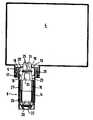
Translated fromKorean제1도는 음료농축액 저장용기가 장착된 음료조제기의 사시도.1 is a perspective view of a beverage preparation machine equipped with a beverage concentrate storage container.
제2도 및 제3도는 각 분배기 및 분배기 고정구가 있는 농축액 저장용기 및 분배기 및 분배기 고정구가 없는 농축액 저장용기의 사시도.2 and 3 are perspective views of the concentrate reservoir with each dispenser and dispenser fixture and the concentrate reservoir without the dispenser and dispenser fixture.
제4도는 분배기 및 분배기 고정구가 있는 음료농축액 저장용기의 단면도.4 is a cross-sectional view of a beverage concentrate storage container having a dispenser and a dispenser fixture.
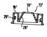
제5도 및 제6도는 분배기 및 분배기 고정구의 입구측 하우징 커버들의 각종형태.5 and 6 illustrate various types of inlet housing covers of the dispenser and the dispenser fixture.
* 도면의 주요부분에 대한 부호의 설명* Explanation of symbols for main parts of the drawings
1 : 하우징 2 : 혼합기1: housing 2: mixer
4 : 저장용기 5 : 연결파이프소켓4: Storage container 5: Connecting pipe socket
6 : 고정구 8 : 덮개6: fixture 8: cover
10 : 포일캡 13 : 하우징덮개10: foil cap 13: housing cover
14 : 분배기하우징 15 : 조절밸브14: distributor housing 15: control valve
본 발명은 저장용기에 사용되는 분배기 및 분배기 고정구, 특히 분배기 하우징과 함께 단위화되어 분배기의 입구측 및 출구측의 배출구들을 교대로 닫을 수 있는 슬라이딩 조절밸브의 고정구에 관한 것이다.The present invention relates to a distributor and a distributor fixture for use in a reservoir, in particular a fixture of a sliding regulating valve which is united with the distributor housing to alternately close the outlets on the inlet and outlet sides of the distributor.
예컨대, 이러한 장치는 바람직하게는 청량음료 제조를 위해 탄산수와 음료농축액을 혼합하는 음료조제기에 사용된다. 음료농축액 저장용기는 대개 크기가 변하지 않고 가스가 침투되지 않는 재료를 사용하여 제작되며 병 또는 입방체 형태를 갖고 있다.For example, such devices are preferably used in beverage preparations which mix carbonated water and beverage concentrates for the production of soft drinks. Beverage concentrate containers are usually made from materials that do not change size and do not penetrate the gas, and are in the form of bottles or cubes.
이러한 저장용기는 음료조제기안에 장착될때 배출구가 아래를 향하도록 배치된다. 슬라이딩 조절밸브에 의해 교대로 닫힐 수 있는 입구측 및 출구측 배출구들을 가진 분배기 및 분배기 고정구가 저장용기의 배출구에 부착된다. 액체(음료농축액)는 고정구의 입구측 배출구가 열릴때 저장용기로부터 분배기 및 분배기 고정구안으로 중력에 의해 흐른다. 슬라이딩 조절밸브에 의해서 이 입구측 배출구가 닫히고 동시에 출구측 배출구가 열리면, 액체는 같은 방법으로 중력에 의해서 분배기로부터 흘러나오게 되는데, 흘러나오는 액체의 양은 분배기 용량에 의해서 결정된다.Such a reservoir is arranged with the outlet facing down when mounted in the beverage preparation. Dispensers and distributor fixtures with inlet and outlet outlets which can be alternately closed by sliding control valves are attached to the outlet of the reservoir. Liquid (beverage concentrate) flows by gravity from the reservoir into the distributor and distributor fixture when the inlet outlet of the fixture is opened. When the inlet outlet is closed by a sliding control valve and at the same time the outlet outlet is opened, the liquid flows out of the distributor by gravity in the same way, the amount of liquid flowing out is determined by the distributor capacity.
그러나 선행기술의 분배기 및 분배기 고정구에서는, 슬라이딩 조절밸브 및 분배기 하우징 사이에서의 누출이 제어가 곤란할 정도로 분배된 양에 영향을 미칠 수 있다. 슬라이딩 조절밸브 및 분배기 하우징 사이에서 이러한 누출흐름을 피하도록 가능한 한 틈이 없도록 하는 안내면의 설계가 크게 문제화되어 있는데, 그 이유는 이 슬라이딩 조절밸브가 분배기 하우징내에서 축방향으로 쉽게 이동이 가능하게 되어 전기적으로 형성된 자장에 의해 솔레노이드 플런저의 형태로 확실하게 조절될 수 있기 때문이다. 이러한 조절방법에서는 기계적 연결이 불필요하므로 음료조제기에서 저장용기의 분배기 및 분배기 고정구의 교체가 쉽게 이루어질 수 있다.However, in the prior art distributors and distributor fixtures, leakage between the sliding regulating valve and the distributor housing can affect the amount dispensed to such an extent that control is difficult. The design of the guiding surface to avoid gaps as much as possible to avoid this leakage flow between the sliding regulating valve and the distributor housing is a major problem because the sliding regulating valve can be easily moved axially within the distributor housing. This is because the magnetic field, which is electrically formed, can be reliably controlled in the form of a solenoid plunger. In such a control method, since no mechanical connection is required, the dispenser and the dispenser fixture of the storage container can be easily replaced in the beverage preparation machine.
부피를 균일하게 하기 위한 역기류 및 대기이하 압력발생에 의해서 액체의 흐름이 방해받지 않도록 하기 위하여 저장용기내의 상부공간(head room)을 배기시키는 것이 가능하다(독일특허 제DE OS 25 44 671호). 이러한 방법은 추가적인 기술적 노력이 필요하며, 아직 유익한 것으로 판명되지 않았는데, 그 이유는 저장용기의 상부공간내의 공기가 쉽게 배출되어 액체의 흐름중에 저장용기의 상부공간에 들어가기 때문이다. 심지어, 선행기술 시스템에서는 상부공간에 대기이하 압력을 형성시켜서 분배플런저 및 분배기 하우징의 벽사이의 누출흐름에 역작용을 가하는 것이 편리한 것으로 판명되었다. 그러나, 체적상 안정된 저장용기안의 압력은 외부의 영향에 따라 특히 단속적인 냉각중의 온도변화에 따라 변한다.It is possible to vent the head room in the storage vessel so that the flow of liquid is not disturbed by backflow and sub-atmospheric pressure for uniform volume (German Patent No. DE OS 25 44 671). . This method requires additional technical effort and has not yet been found to be beneficial because the air in the upper compartment of the reservoir is easily discharged and enters the upper chamber of the reservoir during the flow of liquid. Even prior art systems have proved convenient to create subatmospheric pressure in the upper space to counteract the leakage flow between the dispensing plunger and the wall of the distributor housing. However, the pressure in a volume-stable storage container changes with external influences, in particular with temperature changes during intermittent cooling.
그러므로, 본 발명의 주목적은 환경의 영향과 관계없이 정확한 용적의 분배를 가능케하는 분배기 및 분배기 고정구를 제공하는 것이다. 이를 테면, 음료조제기에서 음료성분들이 반복제조가 가능한 비율로 혼합되도록 하기 위해 고도의 분배정확도가 필요하게 된다.Therefore, it is a primary object of the present invention to provide a dispenser and distributor fixture that allows for accurate volume distribution regardless of environmental influences. For example, a high level of distribution accuracy is required in order to ensure that the beverage ingredients are mixed at a rate capable of repetitive production.
이러한 요구조건에 적합한 설계는 본 발명에 따라 분배기 및 분배기 고정구의 상부공간의 중앙에 분배기 및 분배기 고정구의 입구측 배출구를 배치하고, 이 배출구의 반대편에 튜브형 슬라이딩 밸브상에 밸브 밀폐디스크를 설치하는 것을 특징으로 하는데, 배출구는 이 밀폐 디스크에 의해 리드(lid) 형태로, 슬라이딩 밸브의 이동방향으로 분배기 하우징의 전체 내부에 대해 닫혀질 수 있게 된다. 이 단계에 의해 저장용기로부터 나온 액체는 제어될 수 없는 누출흐름을 가로질러 계속 흐르게 된다. 결과적으로, 저장용기내의 압력은 더 이상 분배량에 영향을 미칠 수 없게 된다. 액체 분배량은 오직 분배기 하우징에 의해 정해진 실제 부피에 따라 결정된다.A design suitable for this requirement is to arrange the inlet side outlet of the distributor and distributor fixture in the center of the upper space of the distributor and distributor fixture according to the invention, and to install a valve closure disc on the tubular sliding valve opposite the outlet. It is characterized in that the outlet can be closed by the closing disc in the form of a lid with respect to the entire interior of the distributor housing in the direction of movement of the sliding valve. This step causes the liquid from the reservoir to continue to flow across uncontrollable leaks. As a result, the pressure in the reservoir can no longer affect the dispense amount. The liquid dispense amount is only determined by the actual volume defined by the dispenser housing.
종종 음료조제기내에서 음료-농축액을 냉각하는 것이 필요하거나 또는 유용하다. 일반적으로, 냉각단계는 간헐적으로 일어난다. 저장용기내의 온도는 간헐적 냉각단게중에 개량 및 냉각기술에 따라서 변동한다. 이러한 온도변동은 체적상 안정되게 설계된 저장용기에 압력변동을 일으킨다. 계량부분에서 분배된 액체의 배출을 위한 유연한 포일자루를 사용하므로써 용적 균일화가 이루어져서 저장용기내의 내부압력의 심각한 변화를 방지하게 된다. 그러나, 상부공간의 중심에 배치되어 슬라이딩 조절밸브의 밸브 밀폐 디스크에 의해 리드(lid) 형태로 닫힐 수 있는 입구측 배출구를 가진 특수형태의 분배기 및 분배기 고정구는 또한 저장용기내의 압력차가 분배량에 대해 어떤 영향을 미칠 수 없게 만든다.It is often necessary or useful to cool the beverage-concentrates in the beverage preparations. Generally, the cooling step occurs intermittently. The temperature in the storage vessel varies with intermittent cooling stages in accordance with improvements and cooling techniques. These temperature fluctuations cause pressure fluctuations in the storage container designed to be stable in volume. By using a flexible foil bag for the discharge of the liquid dispensed in the metering section, volume uniformity is achieved to prevent significant changes in the internal pressure in the reservoir. However, special types of distributors and distributor fixtures having inlet outlets which are arranged in the center of the upper space and which can be closed in the form of lids by the valve closing discs of the sliding control valves, are also known as the pressure difference in the reservoir. It can't affect anything.
바람직한 실시예에 따르면, 본 발명에 따른 분배기 및 분배기 고정구는 밸브 밀폐 디스크 위에 분배기 및 분배기 고정구의 입구측 배출구 안으로 돌출한 안내리드들이 장착된 것을 특징으로 한다. 이것은 슬라이딩 조절밸브를 위한 안내면을 분배기 및 분배기 고정구의 입구측 배출구까지 축방향으로 연장한다.According to a preferred embodiment, the distributor and distributor fixture according to the invention is characterized in that the guide leads protruding into the inlet side outlet of the distributor and distributor fixture on the valve closure disc. This axially extends the guide surface for the sliding regulating valve to the inlet side outlet of the distributor and distributor fixture.
또다른 바람직한 실시예에 따르면, 세로방향의 안내리브들이 튜브형 슬라이딩 조절밸브의 외측 자켓과 분배기 및 분배기 고정구의 원통형벽 사이에 장착된다. 그리하여, 슬라이딩 조절밸브 및 분배기 하우징의 벽사이의 틈은 충분히 확대될 수 있기 때문에 슬라이딩 조절밸브가 분배기안에 접촉하게 되는 위험이 없어지게 되며, 따라서 슬라이딩 조절밸브와 분배기 하우징 사이의 마찰을 줄이게 된다. 제작의 견지에서, 튜브형의 슬라이딩 조절밸브의 외측 자켓상에 세로방향의 안내리브들을 설치하는 것이 유익하다.According to another preferred embodiment, longitudinal guide ribs are mounted between the outer jacket of the tubular sliding control valve and the cylindrical walls of the distributor and distributor fixture. Thus, the gap between the sliding control valve and the wall of the distributor housing can be sufficiently enlarged so that there is no risk of the sliding control valve coming into contact with the distributor, thus reducing the friction between the sliding control valve and the distributor housing. In terms of fabrication, it is advantageous to install longitudinal guide ribs on the outer jacket of the tubular sliding control valve.
분배기 및 분배기 고정구의 주요 부품들을 표준화하고 슬라이딩 조절밸브의 작동 스트로크를 또한 균일한 길이로 만드는 것이 바람직하다. 이 단계는 장치 하우징의 전자석 시스템에 의해서 발생된 자속이 솔레노이드 플런저처럼 작동되는 슬라이딩 조절밸브를 조절하도록된 음료조제기에서의 사용에 매우 중요하다. 부품을 표준화하고 작동 스트로크를 균일한 길이로 하므로써 또한 발생된 자속도 표준화할 수 있다. 그럼에도 불구하고, 계량할 액체, 즉 여러 음료농축액들의 상이한 성질 때문에 액체의 상이한 양을 계량하기 위한 하나의 옵션이 있어야 한다. 사용하는 음료농축액의 특별한 형태에 따라서, 다른 성분, 즉 탄산수와의 혼합비율도 상이하게 할 필요가 있다.It is desirable to standardize the main parts of the distributor and distributor fixtures and to make the operating stroke of the sliding regulating valve also a uniform length. This step is very important for use in beverage dispensers in which the magnetic flux generated by the electromagnet system of the device housing is adapted to regulate a sliding control valve acting like a solenoid plunger. By standardizing the part and making the working stroke uniform, the generated magnetic flux can also be normalized. Nevertheless, there must be one option for weighing different amounts of liquid due to the different nature of the liquid to be weighed, ie the various beverage concentrates. Depending on the particular form of the beverage concentrate to be used, the mixing ratio with other components, that is, carbonated water, needs to be different.
이렇게 상이하게 계량된 분량을 얻기 위하여, 또한 그럼에도 불구하고 가능한 한 단위화된 분배시스템에 의존하기 위하여 본 발명의 범위내에서, 입구측 배출구가 내측용적을 감싸는 측면벽을 가진 분배기 및 분배기 고정구에 분리가능하게 고정된 하우징덮개안에 위치하도록 시스템을 설계하는 것이 유리하다.In order to obtain such differently weighed quantities, and nevertheless to rely on the united distribution system as possible, within the scope of the present invention, the inlet outlet splits into a distributor and distributor fixture with side walls that encase the inner volume. It is advantageous to design the system so that it is located in a possibly fixed housing cover.
슬라이딩 조절밸브의 작동 스트로크를 변화시킬 필요없이, 전체 분배기 및 분배기 고정구의 내측용적은 사용하는 농축물에 따라서 측면벽의 면적을 적절히 연장시키거나 축소시키므로써 다양하고 적절하게 조절될 수 있다. 만일 분배기 및 분배기 고정구의 하우징덮개가 액체 콘테이너의 연결파이프 소켓안에 구조적으로 합체되면, 음료농축액의 종류 및 계량된 양 사이에 직접적인 관계가 성립된다.Without changing the operating stroke of the sliding regulating valve, the inner volume of the entire distributor and distributor fixture can be varied and appropriately adjusted by appropriately extending or reducing the area of the side wall depending on the concentrate used. If the housing cover of the dispenser and the dispenser fixture is structurally incorporated in the connecting pipe socket of the liquid container, a direct relationship is established between the type and the quantity of the beverage concentrate.
한편, 저장용기에 저장된 액체의 성질에 따라 분배기 및 분배기 고정구에 의해 용적분배를 실시할 많은 가능성을 제시하고 또 한편으로는 저장용기의 부적절한 사용을 방지하기 위하여, 분배기 및 분배기 고정구의 일부분, 즉 입구측 부분을 조절피스톤으로 닫을 수 있는 배출구를 통해 저장용기의 연결파이프 소켓안에 합체시키는 것이 유리하다. 이 부분은 분배기 및 분배기 고정구의 주요부품에 일단 연결되면 더 이상 사용할 수 없도록 설계된다. 이러한 분배기 부품들을 연결하기 전에, 연결파이프 소켓의 분배개구부는 포일캡으로 견고하게 밀폐된다.On the one hand, part of the dispenser and distributor fixture, i.e., the inlet, is presented in order to present many possibilities for volumetric distribution by the distributor and distributor fixture according to the nature of the liquid stored in the reservoir and to prevent improper use of the reservoir. It is advantageous to incorporate the side part into the connecting pipe socket of the reservoir via an outlet which can be closed by an adjustment piston. This part is designed so that it can no longer be used once it is connected to the main parts of the distributor and distributor fixture. Before connecting these distributor parts, the distribution opening of the connecting pipe socket is tightly sealed with a foil cap.
본 발명을 실시하는 설계의 상세내용은 도면에 표시한 실제 구체예를 참조하면서 아래에 기술한다.Details of the design for carrying out the invention are described below with reference to the actual embodiments shown in the drawings.
제1도에 표시된 음료조제기는 장치 하우징내의 CO2가스가 농축되고 냉각된 물을 혼합기(2)안의 음료농축액과 혼합시켜 이렇게 얻어진 청량음료를 음료용기속으로 분배하는 역할을 한다. 여러가지 종류의 청량음료를 만들기 위하여, 이 경우에서는 음료조제기 안에서 분배개구부가 아래로 향하게 되도록 혼합기(2) 위에 설치된 세개의 저장용기(4)에 세가지 형태의 음료농축액들이 저장된다. 연결파이프 소켓(5)에서 세개의 저장용기(4) 각각이 분배기 및 분배기 고정구(6)의 분배개구부에 결합된다. 이 분배기 및 분배기 고정구는 강자성체 전기자를 가진 슬라이딩 조절밸브를 포함한다. 하우징(1)안에는 분배기 및 분배기 고정구(6)를 위한 배치슬롯(7)의 근처에 자기장을 발생시킬 수 있는 전자석들이 설치되어 있으며, 이 자기장에 의해 슬라이딩 조절밸브가 분배기 및 분배기 고정구 내측에서 작동된다. 그리하여, 음료농축액의 측량된 량이 혼합기(2)로 주입되고 거기서 측량되어 혼합기(2) 속으로 주입된 탄산수와의 혼합작업이 수행된다. 덮개(8)로 닫을 수 있고 저장용기(4)가 수용되어 있는 이 하우징은 냉동기의 냉동순환로에 연결되어서 음료농축액이 차게 저장되어서 혼합 음료용으로 대기된다.The beverage preparation device shown in FIG. 1 serves to distribute the soft drink thus obtained by mixing the concentrated and cooled water of the CO2 gas in the apparatus housing with the beverage concentrate in the
제2도는 액체농축액용 저장용기(4)를 나타낸다. 연결파이프 소켓(5)의 분배개구부는 포일캡(10)으로 밀봉되어 있다. 제3도는 연결파이프 소켓(5)에 장착된 분배기 및 분배기 고정구가 있는 음료농축액용 저장용기(4)를 나타낸다.2 shows a storage container 4 for a liquid concentrate. The distribution opening of the connecting
저장용기(4) 및 음료농축액용 분배기 및 분배기 고정구의 상세한 내용은 제4도에 표시된 단면도로부터 명백해진다. 이 저장용기(4)는 기본적으로 크기가 안정된 입체형이 되게 설계된다. 저장용기(4)의 분배개구부에서 저장용기의 벽은 크기가 안정된 연결파이프 소켓(5)으로 변형되고 여기에 분배기 및 분배기 고정구가 부착된다.The details of the reservoir 4 and the dispenser and dispenser fixture for the beverage concentrate are evident from the cross section shown in FIG. This storage container 4 is basically designed to have a three-dimensional shape of stable size. At the dispensing opening of the reservoir 4 the wall of the reservoir is deformed into a connecting
분배기 및 분배기 고정구(6)는 하우징덮개(13)로 넓혀진 입구측 분배기 하우징(14)으로 형성되고 이 속에는 수직으로 조정이 가능한 튜브형 슬라이딩 조절밸브(15)가 설치되어 있다.The distributor and the
하우징덮개(13)는 저장용기(4)의 연결파이프 소켓(5)의 구성 부품이다. 분배기 및 분배기 고정구의 하우징(14)은 원주를 따라서 분포된 짧은 나사(29)에 의해서 하우징덮개(13)에 연결되고 하우징덮개(13)에 대해서는 패킹판(16)에 의해 밀폐된다. 밀페링(17)은 공기가 통하지 않게 밀폐하도록 제공되는데, 이것은 제조기술상 나사(25)를 만들기 위하여 하우징덮개(13)의 상부페쇄벽에 개구부(18)가 형성되기 때문이다.The
본질적으로 회전 대칭 설계된 분배기 및 분배기 고정구(6)에는, 입구측 배출개구부(19)가 하우징덮개(13)안에서 축방향으로 중앙에 배치되고 출구측 배출개구부(20)는 분배기 하우징(14)의 하부단부에 배치된다. 이들 배출개구부(19,20)의 반대측에는 슬라이딩 조절밸브(15)상에 밸브 밀폐 디스크(21,22)가 설치되며, 이들은 제4도에 표시된 것같이 슬라이딩 조절밸브(14)의 수직단부 위치에 따라서 입구측 배출개구부(19) 또는 출구측 배출개구부(20)를 교대로 닫는다. 이 슬라이딩 조절밸브(15)는 실질적으로 튜브형태를 가지며 구멍(24)이 있는 실린더형 부착물(23)에 입구측의 밸브 밀폐 디스크(21)를 수반한다. 이 밸브 밀폐 디스크(21) 위에는 십자형의 가이드 리브(25)가 입구측 배출개구부(9) 안으로의 안내요소로써 돌출되어 있다. 이 슬라이딩 조절밸브(15)는 강자성체 재질로된 링(26)을 가져서 이것이 장치 하우징속에 설치된 전자석 시스템 내측에서 하나의 솔레노이드 플런저로서 자기장의 유도에 따라 작동되므로써, 슬라이딩 조절밸브는 출구측 배출개구부(20)가 닫혀있는 도면에 도시된 위치로부터 입구측 배출개구부(19)가 닫혀있는 상부위치까지 상승하게 된다. 슬라이딩 조절밸브(15)의 원주표면에는, 세로방향으로 뻗은 가이드 리브들(27)이 배치되므로써, 슬라이딩 조절밸브(15) 및 분배기 하우징(14)의 벽 사이에 마찰방지 특성이 생기게 된다.In the dispenser and
제4도에 표시된 슬라이딩 조절밸브(15)의 이 위치에서, 저장용기(4)에 저장된 음료농축액은 그 자체의 무게에 의해서 입구측 배출개구부(19)를 통하여 분배기 및 분배기 고정구(6)의 내부로 흐를 수 있다. 분배기 및 분배기 고정구(6) 속에 존재하는 공기량은 저장용기(4)속으로 흐른다. 이렇게 유입되는 공기는 정상적으로 냉각된 분배될 음료농축액 보다 온도가 더 높기 때문에 공기가 냉가되고 나면 용적의 감소현상이 발생하지만 본 발명을 실시하는 분배기 및 분배기 고정구를 사용할때 분배 정밀도에 나쁜 영향을 미치지는 않는다. 마찬가지로, 저장용기내의 온도변화, 따라서 용적변화는 간헐적인 냉각 과정 때문에 유해한 영향을 미치지 않게 된다.In this position of the sliding regulating
장치 하우징(4)에 설치된 전자석 시스템으로 자기장을 발생시키므로써, 슬라이딩 조절밸브(15)의 강자성체 링(26)에는 상승력이 작용한다. 결과적으로, 입구측 배출개구부(19)가 밸브 밀폐 디스크(21)에 의해 닫혀서 더 이상의 음료농축액이 저장용기(4)으로부터 분배기 및 분배기 고정구(6)안으로 들어갈 수 없게되고 한편으로는 출구측 배출개구부(20)가 열려서 분배기 및 분배기 고정구(6)에 들어있던 음료농축액이 배출될 수 있다. 흘러나온 양은 분배기 및 분배기 고정구(6)에서 공기로 대체된다. 이러한 분배기 및 분배기 고정구(6)에 의해서, 분배용적에 있어서의 고도의 정밀도가 달성된다. 이러한 정밀도는 혼합기(2)안으로 주입되는 탄산수와의 최적 혼합비율을 얻는데 가장 중요하다.By generating a magnetic field with an electromagnet system installed in the device housing 4, a lifting force acts on the
다른 음료농축액들을 다르게 계량된 부피를 필요로 하게 된다. 기본적인 구조부품들과 합체된 분배기 및 분배기 고정구에서 이러한 요구사항을 충족시키기 위하여, 다른 분배량을 만드는 대신 하우징덮개(13)의 측벽들(28)의 형태를 다르게 하므로써 기술적인 노력을 줄일 수 있게 된다. 제5도는 제4도에 표시된 것과 동일한 하우징덮개(13)를 나타내고 한편 제6도는 배출개구부(19') 쪽으로 경사진 경사벽(28')을 가진 하우징덮개(13')를 나타낸다. 따라서, 만일 하우징덮개(13')가 제6도와 같이 구성되면, 제5도에 표시된 하우징덮개(13)를 사용할때와 비교할때, 이 영역에 용적변화가 일어나서, 전체 분배기 및 분배기 고정구(6)에 대해서도 용적변화가 일어난다. 이러한 하우징덮개(13) 또는 (13')가 탱크(4)의 연결파이프 소켓(5) 속으로 합체되기 때문에, 사용되는 음료농축액들의 성질과 관련하여 직접적인 관계가 형성된다. 더우기, 분배기 및 분배기 고정구(6)에서의 용적감소는 조절기 플런저속으로 추가적인 파이프를 삽입하므로써 가능하게 된다.Different beverage concentrates require differently weighed volumes. In order to meet these requirements in distributors and distributor fixtures incorporating the basic structural components, the technical effort can be reduced by varying the shape of the
하우징덮개로부터 분배기하우징(14)를 제거한 후, 파열 조인트(rupture joint)(30)(제5도의 30으로 표시된 바와 같이 파열 조인트 부분은 다른부분에 비해 얇게 형성되므로써 파열되기 쉽다)는 플랜지로부터 하우징덮개를 절단하는데 사용되며, 이로써 하우징덮개의 후속결합을 신뢰성 없게 만든다.After removing the dispenser housing 14 from the housing cover, the rupture joint 30 (as indicated by 30 in FIG. 5) is more likely to rupture as the rupture joint portion is thinner than the other portion and the housing cover from the flange It is used to cut, which makes subsequent joining of the housing cover unreliable.
Claims (8)
Translated fromKoreanApplications Claiming Priority (2)
| Application Number | Priority Date | Filing Date | Title |
|---|---|---|---|
| DE19863622745DE3622745A1 (en) | 1986-07-07 | 1986-07-07 | BEVERAGE CONCENTRATE STORAGE TANK FOR USE IN BEVERAGE MACHINES |
| DEP3622745.5 | 1986-07-07 |
Publications (2)
| Publication Number | Publication Date |
|---|---|
| KR880001518A KR880001518A (en) | 1988-04-23 |
| KR950007621B1true KR950007621B1 (en) | 1995-07-13 |
Family
ID=6304557
Family Applications (1)
| Application Number | Title | Priority Date | Filing Date |
|---|---|---|---|
| KR1019870007096AExpired - Fee RelatedKR950007621B1 (en) | 1986-07-07 | 1987-07-03 | Beverage concentrate storage container for use in automatic dispensers |
Country Status (12)
| Country | Link |
|---|---|
| US (1) | US4971231A (en) |
| EP (1) | EP0252421B1 (en) |
| JP (1) | JPS6382993A (en) |
| KR (1) | KR950007621B1 (en) |
| AT (1) | ATE56930T1 (en) |
| AU (1) | AU598000B2 (en) |
| CA (1) | CA1306978C (en) |
| DD (1) | DD262419A5 (en) |
| DE (2) | DE3622745A1 (en) |
| ES (1) | ES2017680B3 (en) |
| GR (1) | GR3000833T3 (en) |
| ZA (1) | ZA874832B (en) |
Families Citing this family (13)
| Publication number | Priority date | Publication date | Assignee | Title |
|---|---|---|---|---|
| DE3940877A1 (en)* | 1989-12-11 | 1991-08-01 | Bosch Siemens Hausgeraete | Liq. dispenser with reservoir and pump |
| DE3940876A1 (en)* | 1989-12-11 | 1991-06-13 | Bosch Siemens Hausgeraete | DRIVE DEVICE IN A LIQUID DISPENSING DEVICE, IN PARTICULAR IN A DRINKING MACHINE |
| DE3940879C1 (en)* | 1989-12-11 | 1991-08-08 | Bosch-Siemens Hausgeraete Gmbh, 8000 Muenchen, De | |
| AT403904B (en)* | 1991-08-12 | 1998-06-25 | Kurt Artmann | PORTIONING DEVICE |
| US5966743A (en)* | 1998-02-09 | 1999-10-19 | Flann; Randall D. | Substance dispensing headgear |
| DE60201094T2 (en) | 2001-01-24 | 2005-10-13 | Lindberg & Jensen Aps | Dosing device for a container |
| US7637384B2 (en)* | 2002-08-09 | 2009-12-29 | Crown Packaging Technology, Inc. | Tamper evident closure with locking band and container therefor |
| EP1598311B1 (en)* | 2004-05-18 | 2007-07-11 | Dannemose, Per Henrik | Dosing device for mounting on a container |
| US20090230157A1 (en)* | 2006-06-16 | 2009-09-17 | Wircon A/S | Pouring stopper |
| PL1975486T3 (en)* | 2007-03-28 | 2015-05-29 | Fillon Tech Sas Societe Par Actions Simplifiee | Dispensing valve |
| USD611376S1 (en) | 2009-03-12 | 2010-03-09 | Bemis Manufacturing Company | Portion of a metering device |
| US20170051842A1 (en)* | 2015-08-20 | 2017-02-23 | Novabay Pharmaceuticals, Inc. | Magnetic Valve System |
| US11709084B2 (en)* | 2020-06-29 | 2023-07-25 | Delaware Capital Formation, Inc. | Multi-reservoir liquid dispenser and associated methods |
Family Cites Families (17)
| Publication number | Priority date | Publication date | Assignee | Title |
|---|---|---|---|---|
| US2759641A (en)* | 1956-08-21 | Liquid measuring and dispensing device | ||
| GB1005693A (en)* | 1963-07-26 | 1965-09-29 | Kenwood Mfg Woking Ltd | Dispensing unit |
| GB1192383A (en)* | 1966-08-24 | 1970-05-20 | Autic Dev Ltd | Improvements in or relating to Liquid Measures |
| US3515312A (en)* | 1968-07-08 | 1970-06-02 | Automatic Retailers Of America | Liquid dispenser |
| US3666150A (en)* | 1968-11-07 | 1972-05-30 | Steli Konsult | Arrangement for delivering predetermined quantities of liquid and solid material |
| US3865277A (en)* | 1972-12-05 | 1975-02-11 | Bras Spa | Beverage-dispensing machine |
| DE2544671C3 (en)* | 1975-10-06 | 1979-05-17 | Dagma Deutsche Automaten- Und Getraenkemaschinen-Gesellschaft Mbh & Co, 2067 Reinfeld | Container for the dosed delivery of liquids |
| GB1577909A (en)* | 1977-01-19 | 1980-10-29 | Donaldson P | Liquid dispensing apparatus |
| AU517767B2 (en)* | 1977-10-12 | 1981-08-27 | Moated. W. And Donaldson P | Dispensing measured quantities from bottle |
| JPS5566938U (en)* | 1978-10-30 | 1980-05-08 | ||
| AU545688B2 (en)* | 1980-06-06 | 1985-07-25 | Precision Measures Limited | Dispenser device |
| DE3033874A1 (en)* | 1980-09-09 | 1982-05-06 | Bosch-Siemens Hausgeräte GmbH, 7000 Stuttgart | CONTAINED, ESPECIALLY DISPOSABLE, FOR DRINK CONCENTRATES, WITH A REUSABLE DOSING DEVICE THAT CAN BE ATTACHED TO ITS OPENING, PREFERABLY MAGNETICALLY ACTUATED |
| DE3033873C2 (en)* | 1980-09-09 | 1986-10-09 | Bosch-Siemens Hausgeräte GmbH, 7000 Stuttgart | Dosing valve, in particular for dispensing beverage concentrates in beverage vending machines |
| NL8203177A (en)* | 1982-08-12 | 1984-03-01 | Douwe Egberts Tabaksfab | OUTLET NIPPLE FOR DISPENSING DEVICES OF BEVERAGE CONCENTRATES. |
| US4509690A (en)* | 1982-12-06 | 1985-04-09 | The Cornelius Company | Carbonated beverage mixing nozzle for a dispenser |
| DE3409142A1 (en)* | 1984-03-13 | 1985-09-26 | Bosch-Siemens Hausgeräte GmbH, 7000 Stuttgart | ARRANGEMENT FOR THE DOSED DISPENSING OF LIQUIDS |
| DE3412545A1 (en)* | 1984-04-04 | 1985-10-17 | Gardena Kress + Kastner Gmbh, 7900 Ulm | AUTOMATICALLY CONTROLLED VALVE DEVICE |
- 1986
- 1986-07-07DEDE19863622745patent/DE3622745A1/ennot_activeWithdrawn
- 1987
- 1987-07-01DEDE8787109456Tpatent/DE3765191D1/ennot_activeExpired - Lifetime
- 1987-07-01ATAT87109456Tpatent/ATE56930T1/ennot_activeIP Right Cessation
- 1987-07-01EPEP87109456Apatent/EP0252421B1/ennot_activeExpired - Lifetime
- 1987-07-01ESES87109456Tpatent/ES2017680B3/ennot_activeExpired - Lifetime
- 1987-07-03ZAZA874832Apatent/ZA874832B/enunknown
- 1987-07-03CACA000541278Apatent/CA1306978C/ennot_activeExpired - Lifetime
- 1987-07-03KRKR1019870007096Apatent/KR950007621B1/ennot_activeExpired - Fee Related
- 1987-07-06DDDD87304674Apatent/DD262419A5/ennot_activeIP Right Cessation
- 1987-07-06AUAU75244/87Apatent/AU598000B2/ennot_activeCeased
- 1987-07-07JPJP62170828Apatent/JPS6382993A/enactiveGranted
- 1988
- 1988-05-03USUS07/189,826patent/US4971231A/ennot_activeExpired - Fee Related
- 1990
- 1990-09-17GRGR90400429Tpatent/GR3000833T3/enunknown
Also Published As
| Publication number | Publication date |
|---|---|
| ZA874832B (en) | 1988-02-24 |
| DE3765191D1 (en) | 1990-10-31 |
| US4971231A (en) | 1990-11-20 |
| ES2017680B3 (en) | 1991-03-01 |
| KR880001518A (en) | 1988-04-23 |
| AU598000B2 (en) | 1990-06-14 |
| AU7524487A (en) | 1988-01-14 |
| CA1306978C (en) | 1992-09-01 |
| EP0252421B1 (en) | 1990-09-26 |
| GR3000833T3 (en) | 1991-11-15 |
| DD262419A5 (en) | 1988-11-30 |
| ATE56930T1 (en) | 1990-10-15 |
| DE3622745A1 (en) | 1988-02-04 |
| JPH0462958B2 (en) | 1992-10-08 |
| EP0252421A1 (en) | 1988-01-13 |
| JPS6382993A (en) | 1988-04-13 |
Similar Documents
| Publication | Publication Date | Title |
|---|---|---|
| KR950007621B1 (en) | Beverage concentrate storage container for use in automatic dispensers | |
| FI65975C (en) | ANORDINATION FOR DOSAGE CONDITIONS AV VAETSKOR | |
| US3926342A (en) | Carbonated water producing apparatus | |
| EP0478624B1 (en) | Apparatus for making or dispensing drinks | |
| JP6998882B2 (en) | Adjustable additive supply system and method | |
| US4410108A (en) | Pressure-actuated valve for use with positive displacement filling machine | |
| KR101783493B1 (en) | Apparatus for dispensing a food product | |
| KR960004729B1 (en) | Apparatus for dispensing metered amounts of liquids | |
| CA1252071A (en) | Gravity dispenser | |
| US3669315A (en) | Liquid-dispensing apparatus having electromagnetically operated valve | |
| AU566173B2 (en) | Dispensing measures of liquids | |
| US12006202B1 (en) | Ingredient container valve control | |
| US12410048B2 (en) | Ingredient container | |
| US6149034A (en) | Paste dispenser | |
| US5417260A (en) | Metering-out device, a metering-out valve, and apparatus for timed metering out of liquid | |
| GB883152A (en) | Liquid dispenser | |
| JPH09292040A (en) | Large cutoff cock device mounted on pallet container | |
| US5322198A (en) | Pump-equipped liquid supply system | |
| CA1272705A (en) | Conical fluid nozzle | |
| KR102185972B1 (en) | An Apparatus for Supplying a Standard Quantity of a Liquid | |
| GB2118054A (en) | Dispensing device for a paint mixing machine | |
| EP1222017B1 (en) | Method and means for mixing | |
| US4310287A (en) | Method and apparatus for operating a water-jet pump | |
| ES274187U (en) | Valve for filling in containers of densive, fluid and foaming liquids. (Machine-translation by Google Translate, not legally binding) | |
| AR008020A1 (en) | A LIQUID DISPENSING APPARATUS IN PRE-ESTABLISHED MEASURES |
Legal Events
| Date | Code | Title | Description |
|---|---|---|---|
| PA0109 | Patent application | St.27 status event code:A-0-1-A10-A12-nap-PA0109 | |
| R17-X000 | Change to representative recorded | St.27 status event code:A-3-3-R10-R17-oth-X000 | |
| PG1501 | Laying open of application | St.27 status event code:A-1-1-Q10-Q12-nap-PG1501 | |
| P11-X000 | Amendment of application requested | St.27 status event code:A-2-2-P10-P11-nap-X000 | |
| P13-X000 | Application amended | St.27 status event code:A-2-2-P10-P13-nap-X000 | |
| A201 | Request for examination | ||
| PA0201 | Request for examination | St.27 status event code:A-1-2-D10-D11-exm-PA0201 | |
| E902 | Notification of reason for refusal | ||
| PE0902 | Notice of grounds for rejection | St.27 status event code:A-1-2-D10-D21-exm-PE0902 | |
| T11-X000 | Administrative time limit extension requested | St.27 status event code:U-3-3-T10-T11-oth-X000 | |
| T11-X000 | Administrative time limit extension requested | St.27 status event code:U-3-3-T10-T11-oth-X000 | |
| T11-X000 | Administrative time limit extension requested | St.27 status event code:U-3-3-T10-T11-oth-X000 | |
| P11-X000 | Amendment of application requested | St.27 status event code:A-2-2-P10-P11-nap-X000 | |
| P13-X000 | Application amended | St.27 status event code:A-2-2-P10-P13-nap-X000 | |
| G160 | Decision to publish patent application | ||
| PG1605 | Publication of application before grant of patent | St.27 status event code:A-2-2-Q10-Q13-nap-PG1605 | |
| E701 | Decision to grant or registration of patent right | ||
| PE0701 | Decision of registration | St.27 status event code:A-1-2-D10-D22-exm-PE0701 | |
| GRNT | Written decision to grant | ||
| PR0701 | Registration of establishment | St.27 status event code:A-2-4-F10-F11-exm-PR0701 | |
| PR1002 | Payment of registration fee | St.27 status event code:A-2-2-U10-U11-oth-PR1002 Fee payment year number:1 | |
| LAPS | Lapse due to unpaid annual fee | ||
| PC1903 | Unpaid annual fee | St.27 status event code:A-4-4-U10-U13-oth-PC1903 Not in force date:19980714 Payment event data comment text:Termination Category : DEFAULT_OF_REGISTRATION_FEE | |
| R18-X000 | Changes to party contact information recorded | St.27 status event code:A-5-5-R10-R18-oth-X000 | |
| PC1903 | Unpaid annual fee | St.27 status event code:N-4-6-H10-H13-oth-PC1903 Ip right cessation event data comment text:Termination Category : DEFAULT_OF_REGISTRATION_FEE Not in force date:19980714 | |
| P22-X000 | Classification modified | St.27 status event code:A-4-4-P10-P22-nap-X000 |