KR950007105B1 - System for automatically genreating tool path data for automatic machining center - Google Patents
System for automatically genreating tool path data for automatic machining centerDownload PDFInfo
- Publication number
- KR950007105B1 KR950007105B1KR1019870009793AKR870009793AKR950007105B1KR 950007105 B1KR950007105 B1KR 950007105B1KR 1019870009793 AKR1019870009793 AKR 1019870009793AKR 870009793 AKR870009793 AKR 870009793AKR 950007105 B1KR950007105 B1KR 950007105B1
- Authority
- KR
- South Korea
- Prior art keywords
- tool
- offset
- data
- tool path
- point
- Prior art date
- Legal status (The legal status is an assumption and is not a legal conclusion. Google has not performed a legal analysis and makes no representation as to the accuracy of the status listed.)
- Expired - Lifetime
Links
- 238000005520cutting processMethods0.000claimsdescription51
- 230000003746surface roughnessEffects0.000claimsdescription41
- 238000012545processingMethods0.000claimsdescription38
- 238000003754machiningMethods0.000claimsdescription20
- 238000005070samplingMethods0.000claimsdescription20
- 238000002485combustion reactionMethods0.000claims1
- 238000000034methodMethods0.000description89
- 238000010586diagramMethods0.000description40
- 238000004364calculation methodMethods0.000description13
- 238000013461designMethods0.000description8
- 238000003801millingMethods0.000description8
- 230000006870functionEffects0.000description5
- 239000000047productSubstances0.000description5
- 230000014509gene expressionEffects0.000description4
- 102100040338Ubiquitin-associated and SH3 domain-containing protein BHuman genes0.000description2
- 101710143616Ubiquitin-associated and SH3 domain-containing protein BProteins0.000description2
- 238000003780insertionMethods0.000description2
- 230000037431insertionEffects0.000description2
- 239000000463materialSubstances0.000description2
- 229920000742CottonPolymers0.000description1
- 238000006243chemical reactionMethods0.000description1
- 239000000470constituentSubstances0.000description1
- 238000010276constructionMethods0.000description1
- 238000013523data managementMethods0.000description1
- 230000001419dependent effectEffects0.000description1
- 238000003379elimination reactionMethods0.000description1
- 238000005516engineering processMethods0.000description1
- 239000004744fabricSubstances0.000description1
- 239000012467final productSubstances0.000description1
- 230000010354integrationEffects0.000description1
- 238000007781pre-processingMethods0.000description1
- 238000007430reference methodMethods0.000description1
- 230000001105regulatory effectEffects0.000description1
- 238000011160researchMethods0.000description1
- 239000000126substanceSubstances0.000description1
- 238000010998test methodMethods0.000description1
Images


Classifications
- G—PHYSICS
- G05—CONTROLLING; REGULATING
- G05B—CONTROL OR REGULATING SYSTEMS IN GENERAL; FUNCTIONAL ELEMENTS OF SUCH SYSTEMS; MONITORING OR TESTING ARRANGEMENTS FOR SUCH SYSTEMS OR ELEMENTS
- G05B19/00—Programme-control systems
- G05B19/02—Programme-control systems electric
- G05B19/18—Numerical control [NC], i.e. automatically operating machines, in particular machine tools, e.g. in a manufacturing environment, so as to execute positioning, movement or co-ordinated operations by means of programme data in numerical form
- G05B19/402—Numerical control [NC], i.e. automatically operating machines, in particular machine tools, e.g. in a manufacturing environment, so as to execute positioning, movement or co-ordinated operations by means of programme data in numerical form characterised by control arrangements for positioning, e.g. centring a tool relative to a hole in the workpiece, additional detection means to correct position
Landscapes
- Engineering & Computer Science (AREA)
- Human Computer Interaction (AREA)
- Manufacturing & Machinery (AREA)
- Physics & Mathematics (AREA)
- General Physics & Mathematics (AREA)
- Automation & Control Theory (AREA)
- Numerical Control (AREA)
Abstract
Translated fromKoreanDescription
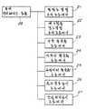
Translated fromKorean제1도는 본원 발명의 공구경로생성시스템의 실시예를 나타내는 CAD/CAM시스템의 전체 구성의 블록도.1 is a block diagram of an overall configuration of a CAD / CAM system showing an embodiment of a tool path generation system of the present invention.
제2도는 공구경로생성시스템의 블록도.2 is a block diagram of a tool path generation system.
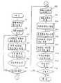
제3도는 공구경로생성시스템의 데이터처리 순서의 플로차트.3 is a flowchart of a data processing sequence of a tool path generation system.
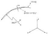
제4도는 기하모델과 설정된 공구경로와의 오차를 나타내는 선도.4 is a diagram showing the error between the geometric model and the set tool path.
제5도는 정밀도결정 프로세스의 원리를 나타내는 선도.5 is a diagram showing the principle of the precision determination process.
제6도는 마무리정밀도결정 프리프로세스의 처리 플로차트.6 is a processing flowchart of the finishing precision determination preprocess.
제7도는 가공물의 표면거칠음의 정의를 나타내는 가공표면의 단면도.7 is a cross-sectional view of a processed surface showing the definition of surface roughness of the workpiece.
제8도는 볼엔드밀을 공구로서 사용했을때의 절삭잔량을 나타내는 단면도.8 is a cross-sectional view showing the remaining amount of cutting when the ball end mill is used as a tool.
제9도는 면거칠음 정도 결정 프리프로세스의 처리 플로차트.9 is a processing flowchart of the surface roughness determination preprocess.
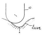
제10도는 자유곡면과 옵셋곡면과의 관계를 나타내는 선도.10 is a diagram showing the relationship between a freeform surface and an offset surface.
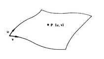
제11도는 파라메트릭표현의 자유곡면을 나타내는 선도.11 is a diagram showing the free surface of parametric representation.
제12도는 자유곡면으로부터 공구경로를 생성하는 한 방법을 나타내는 선도.12 is a diagram showing one method for generating a toolpath from a freeform surface.
제13도는 옵셋 곡면으로부터 공구경로를 생성하는 한 방법을 나타내는 선도.13 is a diagram showing one method for generating a toolpath from an offset surface.
제14도는 공구형상에 기인되는 공구간섭을 나타내는 단면도.14 is a sectional view showing tool interference caused by a tool shape.
제15도는 가공축의 설정조건에 기인되는 공구간섭을 나타내는 단면도.15 is a cross-sectional view showing tool interference caused by setting conditions of a machining axis.
제16도는 공구간섭검정법을 나타내는 단면도.16 is a cross-sectional view showing a tool interference test method.
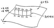
제17도는 “격자(格子)점 높이법”의 알고리즘의 특징을 나타내는 옵셋 다면체의 선도.Figure 17 is a diagram of offset polyhedrons that characterize the algorithm of the "grid point height method".
제18도는 격자점 높이법(제1수법)의 처리순서를 나타내는 플로차트.18 is a flowchart showing the processing procedure of the grid point height method (first method).
제19도는 제18도의 플로차트의 스텝(1)에 대응한 기하곡면의 선도.FIG. 19 is a diagram of a geometric curve corresponding to step (1) of the flowchart of FIG. 18. FIG.
제20도는 스텝(2)에 대응한 옵셋벡터의 선도.20 is a diagram of an offset vector corresponding to step (2).
제21도는 스텝(3)에 대응한 옵셋다면체의 선도.21 is a diagram of an offset polyhedron corresponding to step (3).
제22도는 스텝(4)에 대응한 삼각형(면소)의 선도.22 is a diagram of triangles (facets) corresponding to step (4).
제23도는 스텝(5)에 대응한 XY평면상의 격자점배열의 선도.23 is a diagram of the lattice point array on the XY plane corresponding to step (5).
제24도는 스텝(6)에 대응한 삼각형면소와 격자점과의 관계를 나타내는 선도.24 is a diagram showing a relationship between a triangular facet and a lattice point corresponding to Step (6).
제25도는 스텝(7)에 대응한 삼각형 내부의 격자점의 특정법을 나타내는 선도.25 is a diagram showing a method for specifying a lattice point in a triangle corresponding to step (7).
제26도는 스텝(10)에 대응한 공구경로의 선도.26 is a diagram of a tool path corresponding to
제27도는 공구간섭을 회피한 옵셋곡면의 외포(外包) 곡면을 나타내는 선도.27 is a diagram showing an enveloped curved surface of an offset curved surface avoiding tool interference.
제28도는 다면체에 근사한 옵셋면을 나타내는 선도.28 is a diagram showing an offset plane approximating a polyhedron.
제29도는 격자점 높이법의 순서의 개요를 나타내는 선도.29 is a diagram showing an outline of a procedure of grid point height method.
제30도는 공구간섭을 회피한 옵셋곡면의 외포면을 나타내는 선도.30 is a diagram showing an envelope of an offset curved surface that avoids tool interference.
제31도는 세그멘트 높이법의 원리를 나타내는 선도.31 is a diagram showing the principle of the segment height method.
제32도는 공구간섭을 제거한 선분군의 선도.32 is a diagram of a group of segments removing tool interference.
제33도는 세그멘트 높이법의 처리순서를 나타내는 플로차트.33 is a flowchart showing the processing sequence of the segment height method.
제34도는 제33도의 플로차트의 스텝(1)에 대응한 기하곡면의 선도.FIG. 34 is a diagram of a geometric curve corresponding to step (1) of the flowchart of FIG.
제35도는 스텝(2)에 대응한 옵셋벡터의 선도.35 is a diagram of an offset vector corresponding to step (2).
제36도는 스텝(3)에 대응한 옵셋다면체의 선도.36 is a diagram of an offset polyhedron corresponding to step (3).
제37도는 스텝(4)에 대응한 샘플링위치와 데이터메모리배열을 나타내는 선도.37 is a diagram showing a sampling position and a data memory array corresponding to Step (4).
제38도는 스텝(5)에 대응한 옵셋다면체의 4변형면소를 나타내는 선도.38 is a diagram showing quadrilateral facets of the offset polyhedron corresponding to step (5).
제39도는 스텝(6)에 대응한 세그멘트샘플링의 선도.39 is a diagram of segment sampling corresponding to step (6).
제40도는 스텝(7)에 대응한 선분군의 위치를 나타내는 선도.40 is a diagram showing the position of the line segment group corresponding to step (7).
제41도는 스텝(7)에 대응한 공구간섭제거처리를 행한 선분군의 선도.41 is a diagram of a line segment group that has performed a tool interference elimination process corresponding to step (7).
제42도는 스텝(8)에 대응한 공구경로의 선도.42 is a diagram of a tool path corresponding to step (8).
제43a, b도는 세그멘트 높이법에 있어서 선분의 오버랩 및 크로스를 나타내는 선도.43a and b are diagrams showing line overlap and cross in the segment height method.
제44도는 제33도의 스텝(7)의 처리순서의 상세를 나타내는 플로차트.FIG. 44 is a flowchart showing details of the processing procedure of step (7) of FIG.
제45도-제47도는 두개의 인접한 선분의 위치관계의 여러가지 상태를 나타내는 선도.45 to 47 are diagrams showing various states of the positional relationship of two adjacent line segments.
제48도는 옵셋다면체에 대한 격자점 높이법에 의한 공구경로의 오차를 나타내는 선도.48 is a diagram showing the error of the tool path by the grid point height method with respect to the offset polyhedron.
제49도는 옵셋다면체와 세그멘트 높이법에 의한 공구경로와의 관계를 나타내는 선도.Fig. 49 is a diagram showing the relationship between the offset polyhedron and the tool path by the segment height method.
제50도는 세그멘트 높이법의 처리순서의 개요를 나타내는 선도.50 is a diagram showing an outline of a processing procedure of the segment height method.
제51도는 공구경로 생성시스템의 블록도.51 is a block diagram of a toolpath generation system.
* 도면의 주요부분에 대한 부호의 설명* Explanation of symbols for main parts of the drawings
(1) : 자유곡면생성처리시스템 (2) : 자유곡면절삭용 공구경로 생성시스템(1): Free surface creation processing system (2): Tool path generation system for free surface cutting
(3) : NC 밀링머신 (4) : 입력장치(3): NC milling machine (4): Input device
(5) : 디스플레이 (21) : 정밀도결정 프리프로세서(5): display 21: precision determination preprocessor
(22) : 면거칠음 정도 결정 프리프로세서(22) Predetermination of Surface Roughness
(23) : 거친절삭용 프로세서 (24) : 마무리절삭용 프로세서23: rough cutting processor 24: finishing cutting processor
본원 발명은 3차원 자유곡면을 NC머시닝센터 등으로 자동절삭가공하기 위한 가공정보(공구경로데이터)를 생성하는 장치(시스템)에 관한 것이다.The present invention relates to an apparatus (system) for generating machining information (tool path data) for automatically cutting a three-dimensional free-form surface with an NC machining center.
3차원 자유곡면의 데이터로부터 수치제어공장기계용의 공구경로 데이터를 생성할때에 가공형상의 치수정밀도(공차)를 고려한 다면체 근사(近似)를 행하는 동시에, 가공표면 거칠음을 고려해서 공구 이송폭을 정하고, 다면체 위를 샘플링해서 얻은 좌표와 공구이송폭으로 공구경로데이터를 생성하는 것을 특징으로 하고, 마무리 물품의 정밀도, 표면거칠기등에 과부족이 생기지 않는 최적 공구경로를 고능률로 고속으로 생성시킬 수 있는 장치이다.When generating toolpath data for a numerically controlled factory machine from three-dimensional free-form surface data, a polyhedral approximation taking into account the dimensional accuracy (tolerance) of the machining shape is performed, and the tool feed width is considered in consideration of the roughness of the machining surface. The tool path data can be generated using the coordinates and the tool feed width obtained by sampling on the polyhedron. The optimum tool path can be generated with high efficiency and high speed without causing excessive shortage of the precision and surface roughness of the finished product. Device.
계산기 내부에서 3차원 자유곡면의 데이터를 취급하고, 이들 데이타로부터 최종적인 제품 또는 금형을 NC공작기계등으로 자동가공하기 위한 NC데이터(공구경로데이터)를 생성하는 CAD/CAM시스템이 실용화되어 가고 있다.CAD / CAM systems that handle three-dimensional free-form data inside the calculator and generate NC data (tool path data) for automatically processing the final product or mold from the NC machine are being put to practical use. .
공구경로생성의 한 수법으로서 종래부터 알려져 있는 것에 APT(Automatically programmed Tools)가 있다. APT의 주체는 영어에 유사한 기재 양식을 가진 다축(多軸) 윤곽제어용의 범용(凡用) 자동프로그래밍 언어이다. 이 언어는 공작물과 공구의 기하학적 형상, 공작물에 대한 공구의 운동 외에, 공작기계의 기능, 허용오차, 산술계산등에 관한 명령, 정의를 포함한다. 이 언어로 기술한 프로그램을 대형 컴퓨터에 걸면, NC 테이프를 출력할 수가 있다.One known method for generating tool paths is APT (Automatically Programmed Tools). The principal of APT is a general-purpose automatic programming language for multi-axis contour control with a similar description format in English. This language includes instructions and definitions of machine tool functions, tolerances, arithmetic calculations, etc., in addition to the workpiece and tool geometry and the movement of the tool relative to the workpiece. When a program written in this language is run on a large computer, NC tape can be output.
한편, 계산기내에서 제품 외경 등의 곡면을 취급할 경우 형상의 제어성이 좋다(변형이나 수정이 용이)던가 계산이 용이하다고 하는 설계에 바람직한 성질을 가진
공구경로생성에 내재하는 가장 근본적인 문제는 가공정밀도를 고려한 데이터생성의 효율의 문제 및 공구 간섭판정이 문제이다.The most fundamental problems inherent in tool path generation are problems of efficiency of data generation in consideration of machining precision and tool interference determination.
상기 APT는 사용자가 공구왕복로를 지시(프로그램)하고, 그 결과 자유곡면의 절삭데이터가 생성되는 것으로써 계산기내에서 생성된 기하모델에서 자동적으로 공구경로를 생성하는 것은 아니다. 원래 CAD/CAM 시스템은 설계시의 형상 정보를 가공으로 전달하기 때문에 전체로서 효율이 좋아지는 것이며, APT와 같이 설계는 따로 이루어지고, 요구형상을 의식하면서 가공용의 공구 경로를 프로그램하는 것으로는 효율향상은 바랄 수 없다.The APT does not automatically generate a tool path from the geometric model generated in the calculator by the user indicating (programming) the tool reciprocating path, and as a result, cutting data of the free curved surface is generated. Originally, the CAD / CAM system transmits the shape information at the time of design to the machining, so the efficiency is improved as a whole.The design is done separately like the APT. I can't hope.
한편, 파라메트릭으로 표현된 곡면은 좌표계에 의존하지 않기 때문에 형상의 정의에는 합리적이다. 그러나 곡면을 절삭하는 공작기계는 좌표계가 정해져 있으므로, 계산기내에서 생성한 곡면 데이터로부터 가공데이터(공구경로데이터)에 정밀도 높게 변환할 수는 없다. 이 때문에 가공정밀도가 저하한다. 또한 파라메트릭 표현에 따라서 직접 절삭가공하면, 공구 또는 공구홀더와 마무리형상과의 간섭(충돌)을 체크하는 것이 기술적으로 곤란하며, 필요 부분을 절삭해 버리는 불합리함이 생긴다.On the other hand, since the curved surface expressed in parametric does not depend on the coordinate system, it is reasonable to define the shape. However, since a machine tool for cutting a curved surface has a fixed coordinate system, it is not possible to accurately convert the curved surface data generated in the calculator into the machining data (tool path data). For this reason, processing precision falls. In addition, when cutting directly according to the parametric representation, it is technically difficult to check the interference (collision) between the tool or the tool holder and the finish shape, resulting in unreasonable cutting of the necessary part.
그 밖에 알려져 있는 다면체 근사에 의한 곡면표현으로는 처리능력을 초과하는 방대한 데이터를 취급하지 않으면 충분한 가공 정밀도를 얻지 못한다. 따라서 실용에 응용할 수 있는 정도의 실제 단시간내의 가공데이터의 생성은 도저히 바랄 수 없다. 고속처리를 하기 위해 곡면표현의 데이터수를 적게하면 가공정밀도가 거칠어지고, 설계된 곡면의 공차를 만족할 수 없게 된다.In addition, known surface expressions based on polyhedral approximation do not obtain sufficient processing precision unless a large amount of data is exceeded. Therefore, the generation of the processing data in the actual short time which can be applied to practical use is hardly desired. If the number of data in the surface representation is reduced for high speed processing, the processing precision becomes rough and the tolerance of the designed surface cannot be satisfied.
본원 발명은 상기 문제를 감안하여 공구의 간섭, 비간섭을 판정하면서 필요한 가공정밀도를 만족하는 공구경로데이터를 고속으로 생성하는 것을 목적으로 한다.It is an object of the present invention to generate tool path data at a high speed that satisfies the required machining accuracy while determining the interference and non-interference of a tool in view of the above problems.
본원 발명은 3차원 자유곡면을 표현한 데이터를 가공해서 NC밀링머신과 같은 적어도 3축 제어와 수치제어공작기계용의 공구경로데이터를 생성하는 시스템이다.The present invention is a system for processing data representing a three-dimensional free-form surface to generate tool path data for at least three-axis control and numerically controlled machine tools such as NC milling machines.
자유곡면을 절삭용 면소(面素)로 분할하고, 또한 공구의 형상에 따라서 자유곡면에서 옵셋(offset)시킨 옵셋다면체를 생성하기 위해, 상기 자유곡면과 옵셋다면체와의 차가 부여된 치수정밀도내가 되도록 면소분할수를 결정하는 정밀도결정수단(정밀도 프리프로세서(21))을 구비한다.In order to create the offset polyhedron which is divided into the surface for cutting and the offset polyhedral offset from the free surface according to the shape of the tool, the difference between the free surface and the offset polyhedron is within the given dimensional accuracy. Precision determining means (precision 21) for determining the surface dividing number is provided.
지정된 표면거칠음을 만족하는 가공면이 얻어지도록 표면거칠음 지시치에 따라서 공구이송폭을 결정하는 면거칠음 정도 결정수단(면거칠음정도결정 프리프로세서(22))를 구비한다.Surface roughness determination means (surface roughness determination preprocessor 22) is provided for determining the tool feed width in accordance with the surface roughness indication value so that a machined surface satisfying the specified surface roughness is obtained.
그리고 상기 옵셋다면체의 표면을 샘플링해서 얻어지는 좌표 데이터와 상기 공구이송폭의 데이터에 따라서 공구경로데이터를 생성하는 공구경로생성수단(마무리절삭용 프로세서(23))를 구비한다.And tool path generation means (finishing cutting processor 23) for generating tool path data in accordance with the coordinate data obtained by sampling the surface of the offset polyhedron and the data of the tool feed width.
최종 마무리 물품의 치수정밀도와 표면거칠음을 고려해서 공구경로데이터를 생성하므로, 취급하는 데이타량과 연산량이 최소가되고, 보다 소규모의 계산기로 고속처리가 가능해진다.Tool path data is generated in consideration of the dimensional accuracy and surface roughness of the final finished product, thereby minimizing the amount of data to be handled and the amount of calculation, and enabling a high speed processing with a smaller calculator.
[G1: 시스템 전체의 구성][G1 : System-wide configuration]
제1도에 실시예의 CAD/CAM시스템의 전체 구성을 나타낸다. 제1도에서 자유곡면생성처리시스템(1)은 CAD에 해당하는 부분이며, 목적물의 3차원 자유곡면을 표현하는 기하모델의 형상데이터를 오퍼레이터의 입력조작에 따라서 생성하고, 화일에 축적한다. 목적물은 기계가공부품이나 몰드금형이다.1 shows the overall configuration of the CAD / CAM system of the embodiment. In FIG. 1, the free curved surface
작성된 형상데이터는 자유곡면절삭용 공구경로생성시스템(2)에 있어서 가공데이터, 즉 절삭공구의 이동경로를 결정하는 데이터로 변환된다. 가공데이터는 플로피디스크로 떨어지고, NC밀링머신(3)(NC프라이스반 또는 머시닝센터)에 플로피디스크를 장착하므로서 자동가공이 이루어진다.The created shape data is converted into machining data in the free path cutting tool
자유곡면생성처리시스템(1) 및 자유곡면절삭용 공급경로시스템(2)의 실체는 컴퓨터이며, 유저인터페이스(user interface)를 위해 키보드나 디지타이저 등의 입력장치(4) 및 CRT등의 디스플레이장치(5)가 부속되어 있다.The substance of the free-form
공구경로생성시스템(2)는 (1) 자유곡면의 형상정밀도, (2) 자유곡면의 표면거칠음정도(표면거칠기), (3) 공구간섭체크를 고려하고, 또한 고속으로 가공데이터를 생성하도록 연구된 알고리즘으로 동작한다.The tool path generation system (2) considers (1) the shape precision of the free surface, (2) the surface roughness of the free surface (surface roughness), and (3) the tool interference check, and also generates the machining data at high speed. Works with a modified algorithm.
[G2: 공구경로생성시스템의 구성][G2 : Configuration of Tool Path Generation System]
제2도에 나타낸 바와 같이 공구경로생성시스템은 순차적으로 또는 평행해서 기동되는 복수의 프로그램모듈을 포함한다. 각 프로그램모듈은 전용데이터프로세서라고 생각되므로 이하 프로세서라고 부른다.As shown in FIG. 2, the tool path generation system includes a plurality of program modules that are started sequentially or in parallel. Each program module is called a processor because it is considered a dedicated data processor.
먼저 예비처리단계에서 기동되지만 정밀도결정 프리프로세서(21) 및 면거칠음결정 프리프로세서(22)이다. 정밀도결정 프리프로세서(21)은 목적가공물에 대해서 지정된 공차에 따라서 CAD단계에서 생성된 기하모델의 곡면을 다수의 4변형(또는 3각형)으로 분할하기 위한 분할세밀도를 결정한다. 이 다면체분할에 따라서 공차내에서 근사된 절삭형상(절삭모델)을 생성할 수가 있다. 공차를 고려한 다면체 근사에 의해서 필요 이상으로 고정밀도가 아니고, 더우기 설계시방을 만족하는 절삭가공을 실행하기 위한 최적공구경로를 결정할 수가 있다.First, it is started in the preprocessing stage, but is the
공구경로는 생성된 다면체 위에 설정된다. 즉 공구는 공간내의 점에서 점으로 미세하게 직선운동하면서 곡면을 절삭한다. 이와 같은 절삭가공은 통상의 3축 제어 NC밀링머신으로 실현할 수가 있다.The toolpath is set on the generated polyhedron. In other words, the tool cuts the curved surface while making a fine linear movement from point to point in space. Such cutting can be realized with a conventional three-axis control NC milling machine.
또한 실제의 공구경로는 가공면에 대해서 공구의 날끝에서 공구중심(공구이동의 지령위치)까지 옵셋한 가상의 옵셋다면체 위에 설정된다.In addition, the actual tool path is set on the virtual offset polyhedral offset from the tool edge to the tool center (tool movement command position) with respect to the machining surface.
다음에 면거칠음정도결정 프리프로세서(22)는 목적가공물에 대해서 지정된 표면거칠기에 따라서 공구이송폭(이송피치)를 결정한다. 일반적으로 공구이송폭이 좁으면, 표면은 보다 매끄럽게 절삭된다. 그러나 공구이송폭을 1/2로 하면, 공구경로를 규정하는 데이터량은 2배가 된다. 따라서 최소의 공구경로데이터로 필요한 마무리표면거칠기를 얻기 위해, 공구이송폭은 최적으로 설정되지 않으면 안된다. 면거칠음정도결정 프리프로세서(22)에서는, 부여된 표면거칠기를 만족하는 공구이송폭을 산출하기 위한 알고리즘을 포함한다.Next, the surface
이들 정밀도결정 프리프로세서(21) 및 면거칠음정도결정 프리프로세서(22)에 의해서 얻어진 옵셋다면체의 분할세밀도와 공구이송피치의 데이터는 거친절삭용 프로세서(23) 및 마무리절삭용 프로세서(24)로 이루어진 공구경로생성 프로세서에 보내지고, 이에 따라서 기하모델의 곡면데이터가 순차적으로 처리되어 공구경로데이터가 최종적으로 생성된다. 또한 거친절삭과 마무리절삭과는 공구의 크기와 이송폭과 마무리 이유의 유무가 각각 다를 뿐이고, 데이터처리 알고리즘은 동일하다고 생각해도 된다. 또한 거친절삭 프로세서에 있어서는, 공차와 면거칠음정도에 대해서 고려하지 않아도 된다.The data of the divided fineness and the tool feed pitch of the offset polyhedron obtained by the
이들 공구경로생성의 프로세서(23), (24)의 가장 중요한 기능은 공구간섭을 회피한 공구경로를 결정하는 것이다. 공구간섭은 공구외경이 큰 거친절삭 프로세스에서 가장 생기기 쉽다. 그리고 공구경로생성 알고리즘을 연구하므로서, 이들 프로세서(23), (24)에 있어서 고속으로 공구경로를 생성할 수 있도록 되어 있다. 생성된 공구경로데이터는 거친절삭과 마무리절삭의 순서로 플로피디스크등을 매체로 해서 제1도의 NC밀링머신(3)으로 보내고, 블록소재에 대해서 밀링(프라이스) 절삭가공이 실행된다.The most important function of the
또한 제2도에 나타낸 공구경로생성 시스템에는 파라미터절삭용 프로세서(25)가 부속되어 있고, 파라미터 표현의 원(原) 곡면형상 데이터에 따라서 직접으로 절삭가공하는 것도 가능하게 되어 있다. 이 프로세서(25)에서는 공구간섭체크를 하지 않으나, 간섭이 생기지 않는다고 예측할 수 있는 곡면에 대해서는 곡면형상에 따라서 파라미터절삭을 선택할 수가 있다.In addition, the tool path generation system shown in FIG. 2 is attached with a
그리고 공구경로생성시스템은 공구경로표시 프로세서(26)과 간섭위치표시 프로세서(27)을 포함한다. 이들 프로세서에 의한 3차원 화상표시에 의해 공구경로나 공구간섭을 시각적으로 인식할 수 있다.The tool path generation system includes a tool
공구경로생성시스템의 각 프로세서 또는 프리프로세서는 유저 인터페이스모듈(28)을 통해서 입출력기기와 데이터를 넣고 빼고 할 수 있다. 키보드나 디스플레이, XY플로터 등의 입출력기기를 사용해서, 오퍼레이터는 각 프로세서를 동작시키고 처리결과를 얻을 수가 있다.Each processor or preprocessor of the tool path generation system can insert and extract input and output devices and data through the
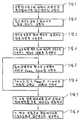
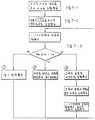
제3도에 제2도의 공구경로생성시스템의 처리 플로차트를 나타낸다. 먼저 곡면데이터를 계산기 화일에서 읽어 넣는다(입력 P1). 다음에 곡면데이터를 표시해서 데이터를 확인한다(표시 P2). 다음에 거친절삭용 프로세스로 진행하고, 거친절삭용 공구경로를 생성시킨다. 거친절삭 프로세서에서는 먼저 마무리여유와 공구경을 지정한다(조작 P3). 이들 지정치와 곡면데이터에 따라서 공구간섭을 회피한 공구경로를 거친절삭용 프로세서(23)(루틴 P4)에서 생성된다. 이로서 생성된 데이터에 의해서 거친절삭용 공구경로, 절삭개시점, 절삭종료점을 표시한다(표시 P5). 이때 불가피한 공구간섭장소가 있으면 이것을 표시한다(표시 P6). 공구간섭이 생긴 경우(판단 P7), 공구경로를 변경하기 위해 조작 P3로 복귀, 재차 공구경로의 생성을 실행한다.3 shows a processing flowchart of the tool path generation system of FIG. First, the surface data is read from the calculator file (input P1). Next, curved data is displayed to confirm the data (display P2). The process then proceeds to a rough cutting process and generates a rough cutting toolpath. In the rough cutting processor, first the finishing margin and the tool diameter are specified (operation P3). According to these specified values and curved surface data, the tool path for avoiding tool interference is generated by the rough cutting processor 23 (routine P4). The tool path for rough cutting, the cutting start point, and the cutting end point are displayed according to the data thus generated (display P5). At this time, if there is an unavoidable place of tool interference, it is displayed (display P6). If tool interference occurs (judgment P7), the tool path is returned to operation P3 to change the tool path, and the tool path is generated again.
판단 P7에서 공구간섭이 없다고 판정되면, 다음의 마무리 절삭 프로세스로 진행한다. 이 프로세스에서는 먼저 마무리 공구경을 지정한다(조작 P8). 그리고 등록되어 있는 일반 공차 테이블의 공차등급(허용공차)를 지정한다(조작 P9). 다음에 마무리 정밀도결정의 프리프로세서(21)(루틴 P10)을 기동하여, 지정된 공사테이블과 절삭치수와의 대조에 의해, 마무리 정밀도(옵셋 다면체에의 분할세밀도)를 결정한다. 그리고 설계도면에 지정된 면거칠음 정도의 값을 입력한다(조작 P11). 이 면거칠음정도 지정치에 의해, 공구이송폭이 마무리 면거칠음정도결정 프리프로세서(22)(루틴 P12)에 의해서 결정된다.If it is determined in tool P7 that there is no tool interference, the process proceeds to the next finishing cutting process. In this process, the finishing tool diameter is first specified (operation P8). Then, the tolerance class (allowed tolerance) of the registered general tolerance table is specified (operation P9). Next, the preprocessor 21 (routine P10) for determining the finishing precision is started, and the finishing precision (divided fineness to the offset polyhedron) is determined by comparing the designated construction table with the cutting dimension. Then, the value of surface roughness specified in the design drawing is input (operation P11). By this surface roughness designation value, the tool feed width is determined by the finishing surface roughness determination preprocessor 22 (routine P12).
다음에 허용공차와 지정면 거칠음정도에 따라서 결정된 다면체의 분할세밀도와 공구이송폭의 데이터에 따라서 마무리 절삭용 프로세서(24)(루틴 P13)을 기동시키고, 마무리절삭용 공구경로를 생성시킨다. 생성된 공구경로데이터에 의해 마무리절삭용 공구경로를 표시시키는 동시에, 공구간섭장소를 표시시킨다(표시 P14, P15), 공구간섭이 생겨 있으면, 판단 P16에 조작 P8로 복귀하고, 부분적으로 마무리 공구경로를 변경하고, 재차 공구경로를 생성시킨다. 이 공구변경에 의해 간섭이 제거되면, 생성된 경로데이터를 화일에 기입해서 일련의 처리가 종료한다.Next, the finishing cutting processor 24 (routine P13) is started in accordance with the data of the divided fineness of the polyhedron and the tool feed width determined according to the tolerance and the degree of roughness of the designated surface, thereby generating a tool cutting path for finishing cutting. The tool path data for finishing cutting is displayed on the basis of the generated tool path data, and the place of tool interference is displayed (indications P14 and P15). If there is any tool interference, the process returns to operation P8 in judgment P16, and the tool path is partially finished. Change the value and generate the tool path again. When the interference is eliminated by this tool change, the generated route data is written to the file to complete a series of processes.
[G3: 정밀도결정 프리프로세서의 상세][G3 : detail of precision determination preprocessor]
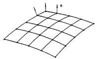
제4도에 기하모델과 생성된 공구경로와의 오차를 나타낸다. X-Y-Z의 3축 제어에 의해 가공하는 경우, 공구는 경로 G에 나타낸 바와 같이 공간내의 점에서 점으로 직선운동한다. 따라서 곡면을 절삭하는 경우, 곡면(기하모델 S)과 절삭한 형상(절삭모델)과의 사이에 차가 생긴다. 이 차를 작게 하는데는, 기하모델에서 다수점을 샘플링해서 취해야 한다. 그러나 샘플링점이 과다하면, 방대한 공구경로데이터가 생성되고, 공작기계의 기억용량을 초과해 버린다. 반대로 데이터의 수를 감소시키며, 곡면부가 직선으로 절삭되어 버리기 때문에 곡면감이 희박해진다.Figure 4 shows the error between the geometric model and the generated toolpath. In the case of machining by three-axis control of X-Y-Z, the tool moves linearly from point to point in space as shown in the path G. Therefore, when cutting a curved surface, a difference arises between the curved surface (geometric model S) and the cut shape (cutting model). To make this difference small, we need to sample a number of points in the geometric model. However, if the sampling point is excessive, a large amount of tool path data is generated and the storage capacity of the machine tool is exceeded. On the contrary, the number of data is reduced, and the curved surface becomes thin because the curved portion is cut in a straight line.
이 때문에 설계시에 설정된 일반공차(특별지정이 없는 부분의 치수의 허용오차)를 만족할만한 샘플링수를 결정할 필요가 있다.For this reason, it is necessary to determine the number of sampling that satisfies the general tolerance (dimension tolerance of the part without special designation) set at the time of design.
일반공차는 JIS 또는 각 제조자에 있어서 규정되어 있으며, 예를 들면 출원인에 있어서 사용하고 있는 일반공차등급의 STS-1은 표 1과 같다.General tolerance is prescribed | regulated by JIS or each manufacturer, For example, STS-1 of the general tolerance grade used by the applicant is shown in Table 1.
[표 1]TABLE 1
일반공차등급 STS-1(단위 mm)General tolerance grade STS-1 (unit mm)

이 표에서, 제4도의 곡율반경 360mm의 부분의 공차는 ±0.5mm가 된다. 따라서 기하곡면 S와 공구경로 G와의 오차가 0.5mm이하가 되도록 다면체에의 분할세밀도를 결정하면 된다.In this table, the tolerance of the portion of 360 mm radius of curvature of FIG. 4 is ± 0.5 mm. Therefore, what is necessary is just to determine the division granularity to a polyhedron so that the error of geometric curve surface S and tool path G may be 0.5 mm or less.
제5도에 분할세밀도를 결정하는 원리를 나타낸다. 거리 ℓ의 공구경로 P1, P2를 설정한 경우, 그 중간점 PM은 P1, P2와 동일평면상에 있고, 각 점에 있어서의 곡율반경 ρ도 변화하지 않는다고 생각된다. 최대오차 δ는 상기 중간점 PM에 있어서 생기고,
이다. 식 (1)에서,to be. In equation (1),

이며, 식 (2)에서,In the formula (2),

이며, sin2θ+cos2θ=1이므로,Because itis, sin 2 θ + cos 2 θ = 1,

따라서,therefore,
ℓ2+4(ρ-δ)2=4ρ2ℓ2 +4 (ρ-δ)2 = 4ρ2
ℓ2=4δ(2ρ-δ)……………………………………………………(6)l2 = 4δ (2ρ-δ)... … … … … … … … … … … … … … … … … … … … (6)
δ>0, 2ρ-δ>0이므로Since δ> 0, 2ρ-δ> 0

가 된다.Becomes
이 식(7)에 의해, 오차 δ가 공차내가 되도록 공구경로 P1-P2의 길이, ℓ, 즉 기하모델 곡면상의 샘플링의 폭을 정하는 것이 마무리정밀도 프리프로세서(21)이다.According to the equation (7), the finishing
제6도에 마무리정밀도결정 프리프로세서의 처리플로를 나타낸다. 먼저 계산기 화일에서 곡면데이터를 읽어 넣는다(입력 P1), 그리고 공차등급(랭크)을 지정한다(조작 P2), 공차등급은 곡면이 지니고 있는 제기능이나 소재의 성상(性狀)에 따라서 정한다. 또한 계산기 내부에는, 이미 설명한 표 1과 같이 공차등급마다 치수에 대응하는 허용차의 테이블이 미리 등록되어 있다.6 shows the processing flow of the finishing precision determination preprocessor. First, the surface data is read from the calculator file (input P1), and the tolerance class (rank P2) is specified (operation P2). The tolerance class is determined according to the features of the surface and the properties of the material. In addition, a table of tolerances corresponding to the dimensions for each tolerance class is registered in advance in the calculator as shown in Table 1 described above.
다음에 처리 P3에서 곡면의 곡율반경을 계산하고, 허용차 테이블에 따라서 처리 P4에서 각 곡율반경의 허용차를 결정한다. 이 허용차를 δ로 하여 식 (7)에 대입해서, 샘플링간격 ℓ을 결정한다. ℓ의 값에 따라서 기하모델 곡면을 구성하는 각 면소를 몇개의 4변형으로 분할하느냐가 결정되고, 곡면상의 샘플링점이 정해진다. 이 결과는 공구경로생성프로세서(루틴 P6)에 인도된다. 이 루틴에서는 후술하는 바와 같이, (7)식에 따라서 설정된 격자모양의 샘플링점에 관해서 옵셋다면체를 생성하고, 이 다면체에 따라서 공차를 만족하는 절삭모양(절삭모델)이 얻어지는 공구경로를 생성한다.Next, the radius of curvature of the curved surface is calculated in process P3, and the tolerance of each radius of curvature is determined in process P4 according to the tolerance table. By setting this tolerance as δ and substituting it into equation (7), the sampling interval L is determined. Depending on the value of l, it is determined how many quadrilaterals each surface element constituting the geometric model curved surface is, and the sampling point on the curved surface is determined. This result is passed to the toolpath generation processor (routine P6). In this routine, as described later, an offset polyhedron is generated with respect to the grid-shaped sampling point set in accordance with Equation (7), and a tool path is obtained in which a cutting shape (cutting model) satisfying the tolerance is obtained according to this polyhedron.
[G4 : 면거칠음정도결정 프리프로세서의 상세][G4: Detail of Surface Roughness Determination Preprocessor]
가공부품의 표면거칠기(相度)는 제7도에 나타낸 바와 같이 표면의 요철의 최대치 HMAX(피크피크치)를 가지고 정의할 수가 있다. 설계 도면상은 여러가지의 표면거칠기의 표기가 사용되고 있으나, 규정되어 있는 표면거칠기를 HMAX로 변환하는 것은 용이하다.The surface roughness of the machined part can be defined with the maximum value HMAX (peak peak value) of surface irregularities as shown in FIG. Although various notations of surface roughness are used on the design drawings, it is easy to convert prescribed surface roughness into HMAX .
제8도에 나타낸 바와 같이 앞끝이 반구형상의 볼엔드밀(10)을 공구로 해서 사용할 것을 생각하면 가공물(11)의 절삭잔량에서 표면거칠기를 산출할 수가 있다. 또한 볼엔드밀(10)은 제8도의 도면과 직각방향의 직선경로를 따라서 연속적으로 이동되고, 또한 한개의 직선경로의 절삭이 종료할때마다 이송폭 Δ으로 스텝 이송된다.As shown in Fig. 8, when the front end is used to use the hemispherical
H=R-Rcosθ………………………………………………(8)H = R-Rcos? … … … … … … … … … … … … … … … … … (8)
Δ=2Rsinθ…………………………………………………(9)Δ = 2Rsin? … … … … … … … … … … … … … … … … … … (9)
따라서,

sin2θ+cos2θ=1이므로,sin2 θ + cos2 θ = 1

Δ2=4H(2R-H)……………………………………………(12)Δ2 = 4H (2R-H)... … … … … … … … … … … … … … … … … (12)
H>0, 2R-H>0이면If H> 0, 2R-H> 0

이 식 (13)에 의해, 표면거칠음정도가 지정치이내가 되도록 공구이송폭 Δ을 정하는 것이 면거칠음정도결정 프리프로세서(22)이다. 또한 공구의 스텝이송방향에 대해서 가공면이 경사져 있을 경우에는, 경사각도의 여현(餘弦)을 공구이송폭 Δ에 공해서 경사의 정도에 따라서 이송폭을 좁힐 필요가 있다.In this equation (13), the surface
제9도에 면거칠음정도결정 프리프로세스의 처리 플로를 나타낸다. 먼저 계산기 화일에서 곡면데이터를 읽어 넣는다(입력 P1).9 shows the processing flow of the surface roughness determination preprocess. First read the surface data from the calculator file (input P1).
그리고 면거칠음정도를 여러가지 지칭방법으로 입력하다(조작 P2), 다음으로 면거칠음정도를 미리 계산기내에 등록된 변환테이블에 의해서 최대의 요철 높이 HMAX로 변환한다(처리 P3). 다시, 식(13)을 사용해서 면거칠음정도를 만족하는 공구이송폭 Δ을 정한다(처리 P5). 이 결과는 공구경로생성 프로세스(루틴 P5)로 인도되고, 요구면거칠음정도를 만족하는 공구이송폭이며, 공구경로가 이미 설명한 옵셋다면체 위에 설정된다.Then, the surface roughness is input by various reference methods (operation P2). Next, the surface roughness is converted into the maximum uneven height HMAX by a conversion table registered in the calculator in advance (process P3). Again, using the formula (13), the tool feed width Δ that satisfies the surface roughness is determined (process P5). This result is led to the tool path generation process (routine P5), the tool feed width which satisfies the required surface roughness, and the tool path is set on the offset polyhedron already described.
[G5: 공구경로생성 프로세스의 기본 개념][G5 : Basic Concept of Tool Path Generation Process]
거친절삭용 프로세서(23)가 마무리절삭용 프로세서(24)로 이루어진 공구경로생성 프로세스는 기본적으로는 기하모델의 곡면데이터에서 옵셋다면체를 생성하고, 이 다면체에서 공구간섭이 없는 공구경로데이터를 고속으로 생성하는 순서이다.The toolpath generation process, in which the
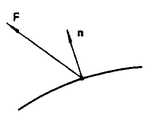
제10도와 같이 볼엔드밀(10)로 자유곡면 S의 점 A를 절삭할 경우, 점 A는 자유곡면과 볼엔드밀의 날면과의 접점이 된다. 이 경우, 볼엔드밀(10)의 구(球)부분의 중심 0과 점 A를 잇는 벡터
일반적으로 곡면상에 있는 점에 있어서의 옵셋벡터란, 그 점을 시발점으로 하고, 그 점을 절삭하기 위해 공구를 접촉시켰을때 공구내에 정한 기준점이 종점이 되는 벡터이다. 벡터 F는 일반적으로 법선벡터 n의 함수 F(n)이다. 볼엔드밀의 경우 F(n)=rn(r은 구면부의 반경)이 된다.In general, an offset vector at a point on a curved surface is a vector whose starting point is the starting point, and the reference point determined in the tool is the end point when the tool is contacted to cut the point. Vector F is generally a function F (n) of normal vector n. In the case of a ball end mill, F (n) = rn (r is the radius of the spherical portion).
자유곡면상의 모든 점에 있어서의 옵셋벡터를 생각하면 그 종점은 하나의 곡면을 형상한다. 이 곡면을 옵셋곡면이라 하면, 분명히 공구중심이 옵셋곡면상에 있도록 공구를 이동시키면, 목적하는 자유곡면을 가공할 수가 있다.Considering the offset vector at all points on the free-form surface, the end point forms one curved surface. If the curved surface is called an offset surface, the desired free surface can be machined by moving the tool so that the tool center is clearly on the offset surface.
옵셋곡면을 기초로 공구경로를 생성하는 가장 단순한 수법은 자유곡면상에서 절삭되는 점의 열을 고려하여, 각 점에 있어서의 옵셋벡터의 종단점(終端店)의 열을 공구경로로 하는 수법이다. 이 수법은 주로 파라메트릭한 식으로 표현된 자유곡면에 대해서 사용되고 있다.The simplest method of generating the tool path based on the offset curve is a method of using the row of the end point of the offset vector at each point as the tool path in consideration of the row of the points to be cut on the free surface. This technique is mainly used for freeform surfaces represented by parametric equations.
예를 들면, 제11도와 같은 파라메트릭 표현의 자유곡면을 생각한다. 곡면상의 점의 위치 P(x, y, z)는,For example, consider a free surface of parametric representation as shown in FIG. The position P (x, y, z) of the point on the surface is
x=f1(u, v)x = f1 (u, v)
y=f2(u, v)y = f2 (u, v)
z=f3(u, v)z = f3 (u, v)
에 의해서 파라미터 u, v의 함수로서 부여된다. 이와 같은 곡면에서는, u, v를 부여하면, 곡면상의 점과 법선방향이 용이하게 구해지므로, u, v를 변화시키므로서 제12도에 나타낸 바와 같이 점열(點列)[A]를 만들고, 이에 대응하는 공구 중심의 점열[0]을 공구경로로서 얻을 수 있다.Is given as a function of the parameters u and v. In such a curved surface, when u and v are given, the points and normal directions on the curved surface are easily obtained. Thus, as shown in FIG. 12, a point sequence [A] is made by changing u and v. The corresponding point sequence [0] of the tool center can be obtained as the tool path.
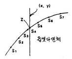
다른 수법으로서, 제13도에 나타낸 바와 같이, 자유곡면에서 그에 대응하는 옵셋곡면을 생성하고, 옵셋곡면상의 점을 파라메트릭으로 지정하므로서 공구경로를 생성하는 수법도 있다. 예를 들면 자유곡면이 다음 식으로 표현되어 있는 경우,As another method, as shown in FIG. 13, a tool path is generated by generating an offset curved surface corresponding to the free curved surface and specifying a point on the offset curved surface as a parametric. For example, if the free surface is represented by
x=g1(u,v)=c11u3+c12u2v+c13uv2+c14v3+c15u2+c16uv+c17v2+c18u+c19v+c1Ax = g1 (u, v) = c11 u3 + c12 u2 v + c13 uv2 + c14 v3 + c15 u2 + c16 uv + c17 v2 + c18 u + c19 v + c1A
y=g2(u,v)=c21u3+c22u2v+c23uv2+c24v3+c25u2+c26uv+c27v2+c28u+c29v+c2Ay = g2 (u, v) = c21 u3 + c22 u2 v + c23 uv2 + c24 v3 + c25 u2 + c26 uv + c27 v2 + c28 u + c29 v + c2A
z=g3(u,v)=c31u3+c32u2v+c33uv2+c34v3+c35u2+c36uv+c37v2+c38u+c39v+c3Az = g3 (u, v) = c31 u3 + c32 u2 v + c33 uv2 + c34 v3 + c35 u2 + c36 uv + c37 v2 + c38 u + c39 v + c3A
자유곡면점 10의 점 P1-P10에서의 옵셋벡터를 고려하여, 그 종점 Q1-Q10을 지나는 곡면으로서, 옵셋곡면을 구할 수가 있다. 이 옵셋곡면에 있어서, 파라미터 u, v를 변화시키므로서 공구경로를 생성할 수가 있다.In consideration of the offset vector at the points P1 -P10 of the free
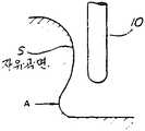
상기 공구경로의 생성수법에서는 공구간섭이 고려되어 있지 않다. 예를 들면 제14a도, b도에 나타낸 바와 같이 A의 부분을 절삭하고져 하면 그 근처의 필요한 부분이 절삭되어 버리고 만다. 이것은 공구형상에 기인하는 공구간섭이다. 또는 제15도에 나타낸 바와 같이, 볼엔드밀의 각도를 바꾸지 않는 한, 공구간섭을 회피해서 A부를 절삭할 수 없는 경우도 생긴다. 이것은 가공축의 설정조건에 기인하는 공구간섭이다.Tool interference is not considered in the generation method of the tool path. For example, as shown in FIG. 14A and FIG. B, when the portion of A is cut off, a necessary portion near the portion is cut off. This is a tool interference due to the tool shape. Alternatively, as shown in FIG. 15, there is a case where the part A cannot be cut by avoiding tool interference unless the angle of the ball end mill is changed. This is a tool interference due to the setting conditions of the machining axis.
공구간섭을 발견하는데는 볼엔드밀과 목적하는 자유곡면과의 교차점을 구하는 계산을 하면 되지만, 이 정도의 정밀도를 얻기 위해서는 다대한 계산시간을 필요로 하기 때문에, 실제로는 공구간섭이 일어나지 않도록 사람이 확인하면서 공구경로를 생성시키고 있다.In order to detect tool interference, a calculation is required to find the intersection point between the ball end mill and the desired free surface.However, to obtain this degree of precision requires a large amount of calculation time, it is necessary to confirm that the tool interference does not actually occur. Creating a toolpath.
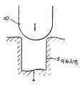
이와 같은 공구간섭문제를 해결하기 위해 제16도와 같은 Z축 방향의 검정법을 사용할 수가 있다. 이 방법으로는, 볼엔드밀의 축을 Z축 방향으로 잡고, Z축과 평행인 직선 ℓ을 고려하여 이것과 옵셋곡면의 교차점을 구한다. 공구간섭이 생겨 있는 경우에는, 도면과 같이 옵셋곡면상의 공구경로가 루프를 그러므로, 한개의 직선 ℓ에 대해서 복수개의 교차점 H1, H2, H3이 구해진다. 이들 교차점의 Z축 방향의 값(높이)에 관하여 가장 큰 값을 가진 점 H1이 공구간섭을 회피한 옵셋면상의 점이 된다.In order to solve such a tool interference problem, a Z-axis calibration method as shown in FIG. 16 may be used. In this method, the axis of the ball end mill is held in the Z-axis direction, and the intersection point of this and the offset curved surface is determined in consideration of the straight line l parallel to the Z-axis. In the case where tool interference occurs, as shown in the drawing, the tool path on the offset curved surface loops, so that a plurality of intersection points H1 , H2 , H3 are obtained for one straight line l. The point H1 having the largest value with respect to the value (height) in the Z-axis direction of these intersection points becomes a point on the offset plane that avoids tool interference.
이와 같은 옵셋곡면은 직선 ℓ의 x, y좌표와 교차점의 z좌표로 표현된다.Such an offset curved surface is represented by the x, y coordinate of the straight line l, and the z coordinate of the intersection point.
[G6: 공구경로생성 프로세스의 구체예]G6 : Specific Example of Tool Path Generation Process
상기 원리에 의한 구체적인 공구경로생성 프로세스는 기본적으로 다음의 스텝으로 이루어진다.The specific tool path generation process based on the above principle basically consists of the following steps.
제1스텝 : 자유곡면에서 옵셋다면체를 생성한다.Step 1: Create an offset polyhedron on the freeform surface.
제2스텝 : XY평면상의 점에 있어서의 옵셋곡면의 최고위치를 구한다.2nd step: The highest position of the offset curved surface in the point on an XY plane is calculated | required.
제2스텝의 알고리즘으로서, XY평면상의 점 군을 격자점으로 지정하여 Z축의 계산을 하는 “격자점 높이법”(제1수법)을 다음에 설명한다. 그리고 이와는 별도로, X축에 평행인 주사선을 따라서 그어진 옵셋면상의 선분(세그멘트)에 관해서 Z축의 계산을 하는 “세그멘트 높이법”(제2수법)을 후술한다.As the algorithm of the second step, the "lattice point height method" (first method) that calculates the Z axis by designating a group of points on the XY plane as a lattice point will be described next. Apart from this, the "segment height method" (second method) for calculating the Z axis with respect to the line segment (segment) on the offset plane drawn along the scanning line parallel to the X axis will be described later.
(Ⅰ) 격자점 높이법(Ⅰ) Grid Point Height Method
제17도에 이 알고리즘의 특징을 나타낸다. 옵셋곡면은 다면체에 근사하다. 대상이 되는 기하모델의 곡면상에 격자모양으로 점 군을 배치하고, 각 점에서의 옵셋벡터(볼엔드밀의 경우는 법선벡터)를 계산하고, 옵셋곡면 위의 격자점을 구한다. 격자(4변형)의 하나 하나를 두개의 3각형으로 분할하면, 옵셋다면체가 얻어진다. 공구 간섭이 있는 부분에는 제17도에 나타낸 바와 같이 Z축 방향으로 옵셋다면체끼리의 겹쳐짐이 있다.Figure 17 shows the features of this algorithm. The offset surface is close to the polyhedron. Place a group of points in the shape of a grid on the curved surface of the target geometry model, calculate the offset vector (or normal vector in the case of ball-end mill) at each point, and find the grid points on the offset surface. By dividing one of the grids (quadrome) into two triangles, an offset polyhedron is obtained. In the part where tool interference exists, as shown in FIG. 17, the offset polyhedrons overlap in the Z-axis direction.
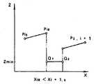
다음에 NC밀링머신의 공구축을 Z축으로 하는 직교좌표계를 취한다. XY평면은 수평면이 된다. XY평면상에 격자점 군(x1, y1)를 부여하고, 각 점에 대응한 옵셋다면체의 높이를 구한다. 이 문제는 XY평면상의 격자점을 지나는 Z축에 평행직선과, 옵셋다면체의 하나의 3각형과의 해(解)(교차점)를 구하는 문제로서 용이하게 풀 수가 있다. 구한 옵셋다면체의 높이 z1, z2의 높은쪽을 선택하므로서 공구간섭을 피할 수가 있다. 공구 경로는 옵셋다면체 위에 설정한다.Next, an orthogonal coordinate system in which the tool axis of the NC milling machine is the Z axis is taken. The XY plane becomes a horizontal plane. A grid point group (x1 , y1 ) is given on the XY plane, and the height of the offset polyhedron corresponding to each point is obtained. This problem can be easily solved as a problem of finding a solution (intersection point) between a parallel line on the Z axis passing through a lattice point on the XY plane and one triangle of an offset polyhedron. Tool interference can be avoided by selecting the higher height of the offset polyhedron z1 and z2 obtained. The tool path is set on the offset polyhedron.
제18도에 격자점 높이법의 처리순서를 나타낸다.18 shows a processing procedure of the grid point height method.
[스텝 1(제19도)][Step 1 (Fig. 19)]
기하모델 곡면상의 격자점에서의 법선벡터 n을 구한다. 각 격자점(샘플점)은 이미 설명한 정밀도 결정프리프로세서(21)의 결과(샘플링간격 ℓ)을 기초로 요구 공차를 만족하도록 곡면 위에 격자모양으로 배치하므로서 얻어진다. 격자간격, 즉 다면체에의 분할세밀도는 그 곡면마다의 곡율과 지정된 공차등급으로 정해진다.Find the normal vector n at the grid points on the surface of the geometric model. Each lattice point (sample point) is obtained by arranging in a lattice shape on a curved surface so as to satisfy a required tolerance based on the result (sampling interval L) of the
또한 제19도는 기하모델을 구성하는 면소의 1매(패치)를 나타내고, 이것은 16개의 제어점에 의해 파라메트릭에 표현되어 있다. 이 패치를 격자모양으로 세분할때에 정밀도결정 프리프로세서(21)에 의한 결과를 사용하여, 최종 마무리형상이 공차내에 들어갈 수 있는 분할을 하고 있다.Fig. 19 also shows one sheet (patch) of cotton fabrics constituting the geometric model, which is represented parametrically by 16 control points. When the patch is subdivided into a lattice shape, the result obtained by the
[스텝 2(제20도)][Step 2 (Fig. 20)]
각 점에서의 법선벡터 n에서 옵셋벡터 F를 구한다. 함수 F(n)는 공구형상에 의해 결정한다.Find the offset vector F from the normal vector n at each point. The function F (n) is determined by the tool geometry.
[스텝 3(제21도)][Step 3 (Fig. 21)]
옵셋벡터의 종점에서 정해지는 옵셋곡면 위의 각 4변형을 둘로 분할하여 3각형을 면소로 하는 옵셋다면체를 얻는다.Offset polyhedrons are triangulated by dividing each of the quadrilaterals on the offset surface determined at the end point of the offset vector into two.
[스텝 4(제22도)][Step 4 (Fig. 22)]
옵셋다면체를 구성하는 하나의 3각형을 취하고, 그 3정점을 지나는 평면의 방정식을 구한다.Take one triangular constituent of the offset polyhedron and find the equation of the plane passing through those three vertices.
z=C1X+C2y+c3z = C1X + C2 y + c3
[스텝 5(제23도)][Step 5 (Fig. 23)]
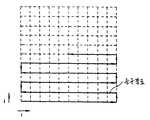
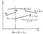
XY평면 위에 격자점(i, j)를 고려하고, 그 점의 좌표(xij, yij)를,Consider the grid points (i, j) on the XY plane, and plot the coordinates (xij , yij ) of that point,
xij=iㆍΔ+xcxij = i · Δ + xc
yij=jㆍΔ+ycyij = j.Δ + yc
로 정한다. (xc, yc)은 정점(定點)의 좌표이며, Δ는 격자간격이다.Decide on (xc , yc ) is the coordinate of the vertex, and Δ is the lattice spacing.
Δ는 이미 설명한 면거칠음정도결정 프리프로세서(22)이며, 설계시에 부여된 표면거칠기 지정에서 산출한 공구이송폭과 같든가 또는 그 이하의 값으로 설정한다.Δ is the surface
여기서 z(i, j)라는 배열의 메모리를 준비하고, 점(i, j)에 있어서의 3각형의 z축 방향의 높이를 기억하는 장소로 할당한다.Here, a memory of an array called z (i, j) is prepared and assigned to a place to store the height of the triangular z-axis direction at the point (i, j).
[스텝 6(제24도)][Step 6 (Fig. 24)]
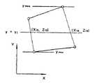
3각형의 XY평면에의 정사영(正射影)을 고려하여, 3각형에 대응한 XY평면의 격자점 군을 한정한다. 이 점 군은 3각형의 정점을 지나는 X축과 Y축에 평행인 직선 xmin, xmax, xmin, xmax(제24도의 점선)으로 구획된 장방형의 내부로 한정할 수가 있다.In consideration of orthogonal projection to a triangular XY plane, a group of grid points of the XY plane corresponding to the triangular shape is defined. This point group can be limited to the interior of a rectangle divided by straight lines xmin , xmax , xmin , and xmax (dotted line in FIG. 24) parallel to the X and Y axes passing through the triangle vertices.
[스텝 7(제25도)][Step 7 (Fig. 25)]
스텝 6에서 한정한 점 군(i, j)이 3각형의 정사영의 내부에 포함되는지의 여부를 판정한다. 그곳에는 예를 들면 점(xij, yij)가 3각형의 한변의 직선(x1, y1)-(x2, y2)에 관해서 점(x3, y3)과 같은쪽에 있는지의 여부를 판정하고, 3각형의 다른 2변에 대해서도 같은 것을 행하면 된다.It is determined whether or not the point groups i and j defined in
3각형의 한변과 일치하는 방정식은, (y-y1)(x2-x1)-(y2-y1)(x-x1)=0가 된다. 좌변을 F(x, y)로 하여, F(xij, yij)와 F(x3, y3)이 같은 부호이면 점(xij, yij)와 점(x3, y3)이 같은 쪽에 있다고 판정된다. 같은 처리를 직선(x2, y2)-(x3, y3), 직선(x3, y3)-(x1, y1)에 따라서 행하고, 점(xij, yij)가 각각 점(x1, y1), (x2, y2)와 같은 쪽에 있으면, 점(xij, yij)는 3각형의 내부에 있다고 판정할 수 있다.The equation that coincides with one side of the triangle is (yy1 ) (x2 -x1 )-(y2 -y1 ) (xx1 ) = 0. If the left side is F (x, y) and F (xij , yij ) and F (x3 , y3 ) have the same sign, then the points (xij , yij ) and point (x3 , y3 ) It is determined to be on the same side. The same process is performed along the straight lines (x2 , y2 )-(x3 , y3 ), straight lines (x3 , y3 )-(x1 , y1 ), and the points (xij , yij ) are respectively If the points (x1 , y1 ) and (x2 , y2 ) are on the same side, it can be determined that the points (xij , yij ) are inside the triangle.
[스텝 8][Step 8]
스텝 4에서 구한 3각형의 3정점을 지나는 방정식에 의해, 점(xij, yij)에 있어서의 3각형의 면상의 높이 zij를 구한다.The triangular plane height zij at the points (xij , yij ) is obtained by the equation passing through the three vertices of the triangle obtained in
zij=C1xij+C2yij+C3zij = C1 xij + C2 yij + C3
[스텝 9][Step 9]
메모리배열 z(i, j)내의 이전의 값과 스텝 8에서 구한 새로운 zij를 비교하여Compare the old value in the memory array z (i, j) with the new zij obtained in
zij>z(i, j)zij > z (i, j)
이면, 메모리 값을 zij로 바꾸어 놓는다. 바꾸어 놓은 부분은 공구간섭이 생기고 있다고 생각된다. 이 처리에 의해 Z축에 관하여, 고위(高位)의 옵셋다면체가 남고 공구간섭이 제거된다., Change the memory value to zij . The changed part is considered to cause tool interference. This process leaves a high offset polyhedron with respect to the Z axis and tool interference is eliminated.
[스텝 10(제26도)][Step 10 (Fig. 26)]
이와 같이 해서 얻어진 메모리내의 z(i, j)에 대응하는 점 군은 옵셋다면체상에 있고, 또한 그 정사영이 XY평면 위의 격자점과 합치하므로, 메모리배열에서 용이하게 경구경로를 생성할 수가 있다. 예를 들면 제26도에 나타낸 바와 같이 i방향으로 연속스캔하고, j방향으로 스텝 이송하므로서 공구경로를 생성한다.The group of points corresponding to z (i, j) in the memory thus obtained are on the offset polyhedron and the orthogonal projections coincide with the lattice points on the XY plane, so that oral paths can be easily generated from the memory array. . For example, as shown in FIG. 26, the tool path is generated by continuously scanning in the i direction and step feeding in the j direction.
실제로는, 3축 밀링머신의 공구를 X축 방향으로 연속이동(스캔)시키면서, 메모리의 어드레스 포인터 i를 증가시킨다. 1구간의 스캔이 종료할때마다 Y축방향으로 공구를 피치 Δ만큼 이동시키고, 어드레스포인터 j를 하나 증가시킨다. Z축 방향의 공구제어는 어드레스(i, j)에 의해서 메모리에서 판독된 값 z(i, j)로 행한다. 가공시간을 단축하기 위해 X축의 공구이동은 제26도에 나타낸 바와 같이 왕복으로 행하는 것이 좋다.In practice, the address pointer i of the memory is increased while continuously moving (scanning) the tool of the three-axis milling machine in the X-axis direction. Whenever scanning of one section is completed, the tool is moved in the Y-axis direction by the pitch Δ, and the address pointer j is increased by one. Tool control in the Z-axis direction is performed with the value z (i, j) read from the memory by the addresses (i, j). In order to shorten the machining time, the tool movement in the X axis is preferably reciprocated as shown in FIG.
그리고 스캔라인을 다른 공구경로 뿐만이 아니고, 등고선을 따른 공구경로를 생성하는 것도 가능하다.It is also possible to generate the scan path along the contour as well as other tool paths.
[종래 기술과의 비교][Comparison with Conventional Technology]
이상 설명한 “격자점 높이법”에 의해 고속으로 공구경로를 생성할 수 있다.The tool path can be generated at high speed by the "grid point height method" described above.
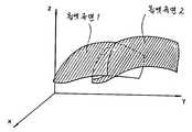
일반적으로는, 공구간섭이 없는 공구경로생성은 제27도에 나타낸 바와 같이 옵셋곡면의 Z축 방향의 외포곡면을 구하는 문제라고 생각할 수가 있다. 외포곡면을 얻는데는 동일 x, y좌표에 있어서의 곡면의 높이 z1(옵셋곡면 1), z2(옵셋곡면 2)를 구하고 대소 비교하면 된다. 그러나 일반적으로는 옵셋곡면이 다음과 같이 파라메트릭한 형태로 표현되어 있다.In general, tool path generation without tool interference can be considered to be a problem of obtaining the outer curved surface in the Z-axis direction of the offset curved surface as shown in FIG. In order to obtain an outer curved surface, the heights z1 (offset curved surface 1) and z2 (offset curved surface 2) of the curved surfaces at the same x and y coordinates may be calculated and compared. In general, however, the offset surface is expressed in a parametric form as follows.
x=ø1(u, v)x = ø1 (u, v)
y=ø2(u, v)y = ø2 (u, v)
z=ø3(u, v)z = ø3 (u, v)
따라서, x, y에서 z를 구하는데는 반복해서 얻어진 필요한 수속(收束) 계산을 사용하지 않으면 안된다. 그리고 곡면이 복수개 존재하는 경우, 점(x, y)를 지나는 곡면을 곡면 전체의 집합에서 탐색하지 않으면 안된다. 따라서 방대한 양의 계산을 하지 않으면 안된다.Therefore, it is necessary to use the necessary procedure calculation repeatedly obtained to find z from x and y. In the case where a plurality of surfaces exist, the surfaces passing through the points (x, y) must be searched in the entire set of surfaces. Therefore, a huge amount of calculations must be made.
파라메트릭에 표현된 옵셋면을 다면체로 근사케하는 방법도 있다. 예를 들면 제28도에서는, 옵셋곡면이 평면 S1-S7에서 이루어지는 다면체로 근사케되어 있다. S1-S7은 선형방정식There is also a way to approximate the face of the parametric offset into a polyhedron. For example, in FIG. 28, the offset curved surface is approximated by a polyhedron formed in the planes S1-S7. S1-S7 is a linear equation
Ψ1=(x, y, z)=0Ψ1 = (x, y, z) = 0
로 표현할 수가 있다. 이 방정식은 용이하게It can be expressed as This equation is easy
z=f1(x, y)z = f1 (x, y)
의 형태로 변경할 수 있으므로, 위치(x, y)를 면 S4가 포함하는 것을 탐색하면, 다음은 반복해서 계산을 하지 않고, z치를 구할 수가 있다.Since the position (x, y) is searched for including the plane S4, the z value can be obtained without performing the calculation repeatedly.
이 수법(격자점 높이법)은 면의 탐색도 하지 않는 것을 특징으로 한다. 그 때문에 위치(x, y)는 격자(Grid)와의 위치라 하고, 격자 위의 높이를 가진 배열 z(i, j)를 준비해 둔다.This technique (lattice point height method) is characterized in that no face is searched for. Therefore, the position (x, y) is called the position with the grid, and an array z (i, j) having a height on the grid is prepared.
그리고 제29도에 나타낸 바와 같이 옵셋다면체 U로부터 순차적으로 평면 Si를 선출하고, 이에 대응하는 위치(i, j)에 있어서의 높이 z를 구하고, 배열 z(i, j)에 써넣어간다(스텝 4-8). 이 방법에서는, 점(x, y)위에 있는 평면 Si를 전 옵셋다면체 중에서 탐색할 필요가 없다. 따라서 옵셋 다면체의 면 Si의 총수 n의 순서로 고속으로 처리할 수가 있다.As shown in FIG. 29, the plane Si is sequentially selected from the offset polyhedron U, the height z at the positions i and j corresponding thereto is obtained, and written in the array z (i, j) (step). 4-8). In this method, the plane Si on the point (x, y) does not need to be searched among full offset polyhedra. Therefore, it can process at high speed in order of the total number n of surface Si of an offset polyhedron.
이에 대해 어떤 xy평면상의 1점의 위치에 대응한 3각형의 탐색을 하면, 해당하는 3각형의 개수를 m로 하고, 총수 m×n의 처리가 필요해진다. 이 오버헤드를 회피하기 위해 종래에는 처리의 대상이 되는 다면체의 수를 줄이는 등의 연구가 필요해지고, 가공 정밀도의 저하가 문제로 되어 있다.On the other hand, when the triangular search corresponding to the position of one point on a certain xy plane is performed, the number of the corresponding triangles is m, and the total number of m x n processes are required. In order to avoid this overhead, researches such as reducing the number of polyhedrons to be processed are conventionally required, and a decrease in machining accuracy is a problem.
(Ⅱ) 세그멘트 높이법(Ⅱ) Segment height method
이 제2수법은 이미 설명한 제1수법인 “격자점 높이법”에서 행하고 있는 격자점마다의 샘플링에 기이하는 정밀도 저하 및 데이터량의 증대의 문제를 회피한 것이다. 제1수법으로는 피절삭물의 완성정밀도가 격자간격에 크게 의존하고, 정밀도가 높은 가공을 하는데는 격자간격을 작게 한 모델의 계산을 고쳐서 할 필요가 있다. 이 제2수법에서는 얻어진 데이터는 옵셋다면체와 같은 정밀도를 가지고 있다. 또한 계산에서 소비하는 메모리의 양을 대폭적으로 적게 하고 있다.This second method avoids the problem of a drop in accuracy and an increase in the amount of data, which is odd in sampling for each grid point performed by the first method described above, which is the "grid point height method". In the first method, the finished precision of the workpiece is largely dependent on the lattice spacing, and in order to perform high-precision machining, it is necessary to correct the calculation of a model having a smaller lattice spacing. The data obtained in this second method has the same precision as the offset polyhedron. It also significantly reduces the amount of memory consumed by calculations.
이 제2수법도 제1수법과 같이 기본적으로는 옵셋곡면의 외포면을 구하는 문제의 해법을 부여하는 것이다.Like the first method, this second method basically provides a solution to the problem of finding the outer envelope of the offset curved surface.
즉 제30도에 나타낸 바와 같이 오버랩하는 옵셋곡면 1, 2중 Z축 방향의 상위의 면에 간섭이 없는 공구경로가 존재한다.That is, as shown in FIG. 30, there is a tool path without interference on the overlapping offset
제31도에 세그멘트 높이법의 특징을 나타낸다. 이 수법으로는, 옵셋면의 표본화를 예를 들면 Y축을 따른 한방향만으로 하므로써 높은 정밀도로 공구경로를 생성할 수 있도록 하고 있다. 즉, 제1수법의 점에서의 샘플링에 대하여, 선에서의 샘플링을 하고 있다. 즉 y좌표가 [yj]의 등간격의 각 위치에서 샘플링을 하도록 한다. 각 위치에서 평면 y=yj를 생각하고, 이 평면을 따라서 옵셋다면체의 단면을 취했을때의 교차선에 대응하는 선분 군을 구한다.Fig. 31 shows the characteristics of the segment height method. In this technique, the tool path can be generated with high precision by sampling the offset plane in only one direction along the Y axis, for example. That is, sampling on a line is performed with respect to sampling at the point of the first technique. In other words, y coordinates should be sampled at the same interval of [yj ]. Consider the plane y = yj at each position, and find the line segment group corresponding to the intersection line when the cross section of the offset polyhedron is taken along this plane.
선분 군의 각각은 옵셋다면체를 이루는 4각형의 각 변과 평면 y=yj와의 교차점을 차례로 이음으로서 얻어진다.Each of the line segment groups is obtained by successively intersecting the intersection point of the plane y = yj with each side of the quadrangle that forms the offset polyhedron.
다음에, 이와 같이 해서 얻어진 선분 군에 따라서, 제32도에 나타낸 바와 같이 Z축 방향의 최대높이를 가진 선분 군을 생성하므로서 공구간섭이 없는 공구경로가 얻어진다.Next, according to the line segment group thus obtained, as shown in FIG. 32, a tool path without tool interference is obtained by generating a line segment group having the maximum height in the Z-axis direction.
제33도에 세그멘트 높이법의 처리 순서를 나타낸다.33 shows the processing procedure of the segment height method.
[스텝 1-3(제34도-제36도)][Step 1-3 (Figs. 34-36)]
제1수법과 같이, 곡면 위에 설정한 격자점에 있어서의 법선벡터를 구하고, 법선벡터로부터 옵셋벡터를 구한다. 옵셋벡터의 종점은 제36도에 나타낸 바와 같이 옵셋곡면 위의 격자점을 형성한다. 또한 격자를 구성하는 요소(4변형)은 평면을 이루지 않으므로 정확하게는 옵셋다면체는 생성되지 않는다.As in the first method, a normal vector at a grid point set on a curved surface is obtained, and an offset vector is obtained from the normal vector. The end point of the offset vector forms a lattice point on the offset curve as shown in FIG. In addition, since the elements constituting the lattice (quadrate) do not form a plane, an offset polyhedron is not generated precisely.
[스텝 4(제37도)][Step 4 (Fig. 37)]
Y축 방향의 각 샘플링위치 yi에 대응하는 옵셋면상의 선분군을 격납하는 메모리배열을 준비한다. 하나의 선분은 개시단 좌표치(xis, zis) 및 종료단의 좌표치(xie, zie)로 표시된다.A memory array for storing a group of line segments on the offset plane corresponding to each sampling position yi in the Y-axis direction is prepared. One line segment is represented by the starting end coordinate values (xis , zis ) and the ending end coordinate values (xie , zie ).
또한 샘플링간격은 이미 설명한 면거칠음정도 결정 프리프로세서(22)에 의해서 도면지정의 표면거칠기를 만족하도록 계산된 공구이송폭 Δ와 같거나 또는 그 이하로 한다.The sampling interval is equal to or less than the tool feed width Δ calculated by the surface
[스텝 5(제38도)][Step 5 (Fig. 38)]
옵셋면상의 격자에서 하나의 4변형 요소를 취하고, y좌표 최소치 ymin및 최대치 ymax를 구한다.Take one quadrilateral element in the grid on the offset plane and find the y-coordinate minimum ymin and maximum ymax .
[스텝 6(제39도)][Step 6 (Fig. 39)]
ymin-ymax의 구간에 들어가는 yi에 대해서 평면 y=yi와 4변형과의 교차점(두개)을 구하고, yi마다 메모리 배열에 교차점의 좌표(xis, zis)(xie, zie)를 기입한다. 이것을 모든 4변형에 대해서 반복한다.For yi in the interval ymin -ymax , find the intersection of the plane y = yi and the quadrilateral (two), and for each yi , the coordinates of the intersection (xis , zis ) in the memory array (xie , zie ). Repeat this for all four variants.
[스텝 7(제40도, 제41도)][Step 7 (40, 41)]
yi마다 선분 군의 데이터를 사용하여, Z축 방향의 최상위의 선분데이터로 변환한다. 즉 yi에 대해서 제40도와 같이 Z축 방향으로 겹쳐짐이 생기고 있는 복수의 선분 군이 얻어져 있는 경우 제41도와 같이 최상위의 선분 군 이외를 소거해서 새로운 선분 군 데이터를 생성한다. 얻어진 선분 군의 데이터는 공구간성을 회피한 공구경로를 나타낸다.The data of the line segment group for every yi is converted into the highest line segment data in the Z-axis direction. That is, when a plurality of line segment groups having overlapping in the Z-axis direction with respect to yi are obtained as shown in FIG. 40, new line segment group data is generated by erasing other than the uppermost line segment group as shown in FIG. The data of the line segment group obtained shows the tool path which avoided the intertool tool.
[스텝 8(제42도)][Step 8 (Fig. 42)]
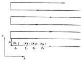
이와 같이 해서 얻어진 제37도의 메모리배열내의 선분 군의 좌표데이터로서 공구경로를 정할 수가 있다. 예를 들면 제42도에 나타낸 바와 같이 x축 방향으로 연속적으로 공구를 등속스캔시키면서 Z축 방향의 공구 높이가 각 선분과 일치하도록 Z축 제어를 한다. Y축 방향에는 공구를 피치 Δ씩 스텝 이동시킨다. 가공시간을 단축하기 위해 X축의 공구이동은 왕복으로 하는 것이 좋다.The tool path can be determined as the coordinate data of the line segment group in the memory arrangement of FIG. 37 obtained in this way. For example, as shown in FIG. 42, the Z-axis control is performed so that the tool height in the Z-axis direction coincides with each line while continuously scanning the tool in the x-axis direction. In the Y-axis direction, the tool is moved in steps of pitch Δ. In order to reduce the machining time, the tool movement in X axis should be reciprocated.
[세그멘트 높이법의 고속연산 알고리즘][High-speed Algorithm of Segment Height Method]
다음에 제33도의 스텝 7(제41도)에서 필요한 연산처리를 고속화하는 수법에 대해서 설명한다. 이 스텝 7에서 행해지는 연산은 Z축에 관하여 최상위의 선분군을 생성하는 과정이며, 가장 시간이 걸리는 처리이다. 연산처리는 제43a, b도의 2타입과 그 조합으로 이루어지는 성분의 위치관계에 대해서 한다. 타입 a도는 두개의 선분의 오버랩이며, 타입 b도는 두개의 선분의 크로스이다. 어느 경우라도 점선부분을 소거하기 위해 선분을 재정의한다.Next, a method of speeding up the arithmetic processing required in Step 7 (FIG. 41) of FIG. 33 will be described. The calculation performed in
타입 a도에서는, 선분


타입 b도에서는, 선분


제44도에 스텝 7의 처리 순서를 상세하게 나타낸다. 스텝 6에서는 옵셋면을 나타내는 선분군의 끝점이 yi마다 구해진 순서로 메모리배열로 축적되어 있다. 각 선분은
Pis=(xis, zis)Pis = (xis , zis )
Pie=(xie, zie)Pie = (xie , zie )
로 되어 있다.It is.
[스텝 7-1][Step 7-1]
xis≤xie가 되도록 xis와 xie를 교환한다. 즉 개시단에서 종료단으로의 방향이 X축의 마이너스방향을 향하고 있는 선분에 대해서는, xie<xis이므로, 개시단과 그 종료단의 x좌표만을 교환하여 전 선분이 X축의 플러스방향을 향하도록 오리엔테이션 한다. z좌표는 변화하지 않았으므로, 각 선분의 높이 즉 공구경로 자체는 변화하지 않는다. 오리엔테이션의 목적은 공구경로를 X축의 한쪽방향으로 한정하기 위해서이다.xis ≤x exchange and xis such that xieie. That is, for a line segment from the start end to the end end in the negative direction of the X axis, xie <xis, so that only the x coordinates of the start end and the end end thereof are exchanged so that all the segments face the positive direction of the X axis. do. Since the z-coordinate has not changed, the height of each line segment, that is, the tool path itself, does not change. The purpose of the orientation is to define the tool path in one direction of the X axis.
[스텝 7-2][Step 7-2]
각 선분
[스텝 7-3][Step 7-3]
i 및 i+1번째가 인접한 선분

① xie=xi+1.s의 경우(제45도)① For xie = xi + 1.s (Fig. 45)
인접한 두개의 선분의 종료단과 개시단과의 x좌표가 일치되어 있는 경우, 공구간섭이 없으므로, i를 하나 증가하고, 새로운 두개의 선분을 취한다.If the x-coordinates of the end and the start of two adjacent line segments coincide, there is no tool interference, so i is increased by one and two new lines are taken.
② xie=x1+1.s의 경우(제46도)② For xie = x1 + 1.s (Fig. 46)
앞의 선분의 종료단과 뒤의 선분의 개시단과의 x좌표가 떨어져 있는 경우에는, 미리 정해진 zmin의 높이를 가진 선분


③ xie=xi+1.s의 경우(제47도)③ For xie = xi + 1.s (Figure 47)
앞의 선분의 종료단이 뒤의 선분의 개시단보다 x축에 관하여 뒷쪽에 있을 경우에는, 선분끼리의 오버랩이 있고, 공구간섭이 생기고 있다. 이 경우에는, 제47도와 같이 두개의 선분의 최대 4개의 구간 Ⅰ-Ⅳ으로 분할한다.When the end of the previous line segment is behind the x-axis from the start of the rear line segment, there is overlap between the line segments, and tool interference occurs. In this case, as shown in FIG. 47, a maximum of four sections I-IV of two line segments are divided.
(a) xis≠Pi+1.s의 경우, 구간 Ⅰ가 존재한다.(a) For xis ≠ Pi + 1.s , interval I exists.
(b) 선분

(c) xis≠xi+1.e의 경우, 구간 Ⅳ이 존재한다.(c) For xis ≠ xi + 1.e , the section IV exists.
다음에 구간 Ⅱ, Ⅲ에 있어서, Z축의 위쪽에 있는 선분을 선택한다. 그리고 원래의 선분

상기 스텝 7-3은 i=n이 될때까지 반복된다. 단 처리중에 n(총수)의 값은 변화한다.Step 7-3 is repeated until i = n. However, the value of n (total number) changes during processing.
상기의 처리에 의해서, 공구간섭의 발생부분을 검지하여 간섭을 배제할 수가 있다. 또한 간섭이 없는 부분에서는, 단순히 제44도의 ① 또는 ②의 처리를 지나는 루프를 돌으므로 매우 고속처리가 가능하다.By the above process, the occurrence of tool interference can be detected and interference can be eliminated. In the absence of interference, the loop simply passes through the processing of ① or ② in FIG. 44, so that very high speed processing is possible.
[격자점 높이법(제1수법)과의 비교][Comparison with Grid Point Height Method (First Method)]
제48도는 격자점 높이법에 의해서 얻어지는 공구경로(실선)과 옵셋다면체(점선)과의 오차를 나타낸다. 이 제1수법에서는 XY평면의 격자점에서 표본화를 하고 있으므로, 표본위치에 의존해서 옵셋다면체를 정확하게 표현할 수 없다. 근사한 정밀도를 높이는데는 샘플링간격 Δ를 작게 할 필요가 있으나, 방대한 메모리의 소비량, 연산시간이 필요하다.Fig. 48 shows the error between the tool path (solid line) and the offset polyhedron (dashed line) obtained by the grid point height method. In this first method, since sampling is performed at grid points of the XY plane, the offset polyhedron cannot be accurately represented depending on the sample position. In order to increase the approximate precision, it is necessary to reduce the sampling interval Δ, but a large amount of memory consumption and computation time are required.
한편, 세그멘트 높이법의 공구경로는 제49도에 나타낸 바와 같이 옵셋다면체 위의 선분(점선)에 대한 직접의 연산처리로 구해지므로 공구경로 생성시에 원리적으로 오차가 생기지 않는다.On the other hand, as shown in FIG. 49, the tool path of the segment height method is obtained by direct arithmetic processing on the line segment (dotted line) on the offset polyhedron, so that no error occurs in principle when generating the tool path.
격자점 높이법으로는, 제29도에 나타낸 바와 같이 옵셋다면체에서 하나의 3각형을 취하고, 그 XY평면에의 정사영을 덮는 격자점의 z좌표를 메모리에 기입하고, 그때에 메모리내의 앞의 값과 비교해서 z치가 큰쪽을 보존하므로서 공구간섭을 제거할 수가 있다. 따라서 연산순서는 단순하고 상당한 고속처리가 기대된다.As the grid point height method, as shown in Fig. 29, one triangular is taken from the offset polyhedron, and the z coordinate of the grid point covering the orthogonal projection to the XY plane is written into the memory, and the previous value in the memory is then. Compared to this, tool interference can be eliminated by preserving the larger z value. Therefore, the operation sequence is simple and considerable high speed processing is expected.
이에 대해서 세그멘트 높이법에서는 제50도에 그 개요를 나타낸 바와 같이 옵셋다면체로부터 하나의 4변형을 취하고, 평면 yi에서 샘플링하여, yi에 대응한 메모리영역에 일단 모든 선분데이터를 격납하고, 이 데이터에 따라서 공구간섭을 제거하는 연산을 한다. 선분데이터는 적당한 순서로 메모리에 격납되므로, 이미 설명한 바와 같이 x좌표에 대해서 소팅을 할 필요가 있다.On the other hand, in the segment height method, as shown in FIG. 50, one quadrilateral is taken from an offset polyhedron, sampled on a plane yi , and once all line segment data is stored in a memory area corresponding to yi . The operation to remove tool interference is performed according to the data. Since the line segment data is stored in the memory in a proper order, it is necessary to sort the x coordinate as described above.
실제로는 격자점 높이법에서는 격자간격 Δ를 상당히 작게 하지 않으면 필요한 정밀도를 얻을 수 없으므로, 연산량은 세그멘트 높이법쪽이 적을 경우가 많다. 그리고 세그멘트 높이법에서는 선분의 양끝의 좌표데이터만을 취급하므로, 메모리영역도 작아도 된다. 따라서 세그멘트 높이법은 보다 공구경로 생성의 효율이 좋고, 소용량의 데이터프로세서로 고정밀도의 공구경로 생성이 가능하다.In practice, in the grid point height method, the required precision cannot be obtained unless the grid spacing Δ is considerably reduced, so the amount of calculation is often smaller in the segment height method. In addition, since the segment height method handles only coordinate data at both ends of the line segment, the memory area may be small. Therefore, the segment height method is more efficient in generating tool paths, and it is possible to generate high-precision tool paths with a small data processor.
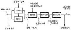
제51도에 세그멘트 높이법에 의한 공구경로생성시스템을 블록도로 나타낸다. 각 블록은 다음 프로그램모듈에 대응한다.51 shows a tool path generation system by the segment height method in a block diagram. Each block corresponds to the next program module.
[DIVIDE][DIVIDE]
Bezier 곡면에서 옵셋다면체를 생성한다(또한 면소는 4변형이며 평면은 아니다).Create an offset polyhedron from the Bezier surface (also facet is quadrilateral, not planar).
[EDGE][EDGE]
경계에서 위치, 접평면이 불연속인 부분을 보충하는 옵셋다면체를 생성한다.Creates an offset polyhedron that compensates for the discontinuities in the position and tangent planes at the boundary.
[SLIGE][SLIGE]
옵셋다면체를 Y축과 직교한 평면으로 절단하고, 선분 군을 생성한다.The offset polyhedron is cut in a plane orthogonal to the Y axis and a line segment is created.
[DPVECT][DPVECT]
공구간섭을 제거하는 연산을 한다.Calculate to eliminate tool interference.
[CRPATH][CRPATH]
계산오차 등에 의해 생기는 잘못된 선분데이터를 제거한다. 그리고 평행으로 이어진 선분의 통합 등의 불필요한 데이터를 제거한다.Eliminate incorrect line segment data caused by calculation errors. Then, unnecessary data such as integration of parallel line segments is removed.
본원 발명은 상기와 같이 최종 마무리 물품의 치수정밀도와 표면거칠음에 관하여 설계시방을 만족하도록 가장 적합한 공구경로 데이터를 생성하였으므로, 취급하는 데이터량에 과부족이 없고, 따라서 데이터생성효율을 높여서 보다 고속처리를 할 수가 있고, 매우 실용성이 높은 자동 가공시스템이 얻어진다.Since the present invention generates the most suitable toolpath data to satisfy the design specification with respect to the dimensional accuracy and surface roughness of the final finished product as described above, there is no oversufficiency in the amount of data to be handled, thus increasing the data generation efficiency to achieve faster processing. A highly practical automatic processing system can be obtained.
Claims (1)
Translated fromKoreanApplications Claiming Priority (4)
| Application Number | Priority Date | Filing Date | Title |
|---|---|---|---|
| JP86-208548 | 1986-09-04 | ||
| JP61208548AJP2531148B2 (en) | 1986-09-04 | 1986-09-04 | Free curved surface processing information generation method |
| JP86-208553 | 1986-09-04 | ||
| JP61208553AJP2652848B2 (en) | 1986-09-04 | 1986-09-04 | Machining information generation method for free-form surface avoiding tool interference |
Publications (2)
| Publication Number | Publication Date |
|---|---|
| KR880004362A KR880004362A (en) | 1988-06-07 |
| KR950007105B1true KR950007105B1 (en) | 1995-06-30 |
Family
ID=26516894
Family Applications (1)
| Application Number | Title | Priority Date | Filing Date |
|---|---|---|---|
| KR1019870009793AExpired - LifetimeKR950007105B1 (en) | 1986-09-04 | 1987-09-04 | System for automatically genreating tool path data for automatic machining center |
Country Status (1)
| Country | Link |
|---|---|
| KR (1) | KR950007105B1 (en) |
- 1987
- 1987-09-04KRKR1019870009793Apatent/KR950007105B1/ennot_activeExpired - Lifetime
Also Published As
| Publication number | Publication date |
|---|---|
| KR880004362A (en) | 1988-06-07 |
Similar Documents
| Publication | Publication Date | Title |
|---|---|---|
| JP2531148B2 (en) | Free curved surface processing information generation method | |
| Chen et al. | Offset surface generation and contouring in computer-aided design | |
| US4868761A (en) | Method for evaluating free surface and NC system thereof | |
| Broomhead et al. | Generating NC data at the machine tool for the manufacture of free-form surfaces | |
| US5953233A (en) | Process of generating discrete points defining cutter path, so as to meet selected workpiece machining requirements | |
| JP2804829B2 (en) | Curved surface processing method | |
| Wang et al. | Five-axis NC machining of sculptured surfaces | |
| JPH07195253A (en) | Processing method of processing CAM system | |
| Inui et al. | Cutter Engagement Feature Extraction Using Triple-Dexel Representation Workpiece Model and GPU Parallel Processing Function. | |
| JP2652848B2 (en) | Machining information generation method for free-form surface avoiding tool interference | |
| KR950007105B1 (en) | System for automatically genreating tool path data for automatic machining center | |
| JP2647650B2 (en) | Generation method of machining information of free-form surface without tool interference | |
| JP2531149B2 (en) | A method for generating machining information of free-form surface in consideration of finishing accuracy | |
| JPH0767659B2 (en) | Free curved surface machining information generation system considering finish surface roughness | |
| Maeng et al. | Feature-based machining of curved surfaces using the steepest directed tree approach | |
| JP2001242919A (en) | Tool reference plane calculation method, computer-readable recording medium storing tool reference plane calculation program, and tool reference plane calculation apparatus | |
| JPS6364110A (en) | Processing information generating system for free curved surface evading tool interference | |
| JP2822194B2 (en) | Method and apparatus for creating a two-dimensional projection diagram of a three-dimensional shape model using a computer | |
| JP2859824B2 (en) | Numerical Control Milling Method for Curved Workpieces by Tracking the Maximum Slope Direction Tree | |
| JP2918192B2 (en) | Processing data creation method | |
| Huang et al. | An image detection approach to NC rough-cut milling from solid models | |
| JP2003044110A (en) | Cutter path generating method for nc contour cutting | |
| Hermann | Algorithms for real-time tool path generation | |
| JPS6324305A (en) | Generating method for tool path data | |
| Bey et al. | A new approach for finishing free-form surfaces based on local shapes |
Legal Events
| Date | Code | Title | Description |
|---|---|---|---|
| PA0109 | Patent application | Patent event code:PA01091R01D Comment text:Patent Application Patent event date:19870904 | |
| PG1501 | Laying open of application | ||
| A201 | Request for examination | ||
| PA0201 | Request for examination | Patent event code:PA02012R01D Patent event date:19920820 Comment text:Request for Examination of Application Patent event code:PA02011R01I Patent event date:19870904 Comment text:Patent Application | |
| G160 | Decision to publish patent application | ||
| PG1605 | Publication of application before grant of patent | Comment text:Decision on Publication of Application Patent event code:PG16051S01I Patent event date:19950531 | |
| E701 | Decision to grant or registration of patent right | ||
| PE0701 | Decision of registration | Patent event code:PE07011S01D Comment text:Decision to Grant Registration Patent event date:19950922 | |
| GRNT | Written decision to grant | ||
| PR0701 | Registration of establishment | Comment text:Registration of Establishment Patent event date:19950926 Patent event code:PR07011E01D | |
| PR1002 | Payment of registration fee | Payment date:19950926 End annual number:3 Start annual number:1 | |
| PR1001 | Payment of annual fee | Payment date:19970828 Start annual number:4 End annual number:4 | |
| PR1001 | Payment of annual fee | Payment date:19980918 Start annual number:5 End annual number:5 | |
| PR1001 | Payment of annual fee | Payment date:19990915 Start annual number:6 End annual number:6 | |
| PR1001 | Payment of annual fee | Payment date:20001017 Start annual number:7 End annual number:7 | |
| PR1001 | Payment of annual fee | Payment date:20020517 Start annual number:8 End annual number:8 | |
| PR1001 | Payment of annual fee | Payment date:20030516 Start annual number:9 End annual number:9 | |
| PR1001 | Payment of annual fee | Payment date:20040517 Start annual number:10 End annual number:10 | |
| PR1001 | Payment of annual fee | Payment date:20050531 Start annual number:11 End annual number:11 | |
| PR1001 | Payment of annual fee | Payment date:20060607 Start annual number:12 End annual number:12 | |
| PR1001 | Payment of annual fee | Payment date:20070531 Start annual number:13 End annual number:13 | |
| PR1001 | Payment of annual fee | Payment date:20080527 Start annual number:14 End annual number:14 | |
| FPAY | Annual fee payment | Payment date:20090527 Year of fee payment:15 | |
| PR1001 | Payment of annual fee | Payment date:20090527 Start annual number:15 End annual number:15 | |
| EXPY | Expiration of term | ||
| PC1801 | Expiration of term |