KR930010545B1 - Apparatus for inspecting fuction of liver - Google Patents
Apparatus for inspecting fuction of liverDownload PDFInfo
- Publication number
- KR930010545B1 KR930010545B1KR1019900007493AKR900007493AKR930010545B1KR 930010545 B1KR930010545 B1KR 930010545B1KR 1019900007493 AKR1019900007493 AKR 1019900007493AKR 900007493 AKR900007493 AKR 900007493AKR 930010545 B1KR930010545 B1KR 930010545B1
- Authority
- KR
- South Korea
- Prior art keywords
- photoelectric conversion
- specific pigment
- blood
- light
- sampling
- Prior art date
- Legal status (The legal status is an assumption and is not a legal conclusion. Google has not performed a legal analysis and makes no representation as to the accuracy of the status listed.)
- Expired - Fee Related
Links
Images


Classifications
- A—HUMAN NECESSITIES
- A61—MEDICAL OR VETERINARY SCIENCE; HYGIENE
- A61B—DIAGNOSIS; SURGERY; IDENTIFICATION
- A61B5/00—Measuring for diagnostic purposes; Identification of persons
- A—HUMAN NECESSITIES
- A61—MEDICAL OR VETERINARY SCIENCE; HYGIENE
- A61B—DIAGNOSIS; SURGERY; IDENTIFICATION
- A61B5/00—Measuring for diagnostic purposes; Identification of persons
- A61B5/02—Detecting, measuring or recording for evaluating the cardiovascular system, e.g. pulse, heart rate, blood pressure or blood flow
- A61B5/026—Measuring blood flow
- A61B5/0261—Measuring blood flow using optical means, e.g. infrared light
- A—HUMAN NECESSITIES
- A61—MEDICAL OR VETERINARY SCIENCE; HYGIENE
- A61B—DIAGNOSIS; SURGERY; IDENTIFICATION
- A61B5/00—Measuring for diagnostic purposes; Identification of persons
- A61B5/0059—Measuring for diagnostic purposes; Identification of persons using light, e.g. diagnosis by transillumination, diascopy, fluorescence
- A—HUMAN NECESSITIES
- A61—MEDICAL OR VETERINARY SCIENCE; HYGIENE
- A61B—DIAGNOSIS; SURGERY; IDENTIFICATION
- A61B5/00—Measuring for diagnostic purposes; Identification of persons
- A61B5/42—Detecting, measuring or recording for evaluating the gastrointestinal, the endocrine or the exocrine systems
- A61B5/4222—Evaluating particular parts, e.g. particular organs
- A61B5/4244—Evaluating particular parts, e.g. particular organs liver
Landscapes
- Health & Medical Sciences (AREA)
- Life Sciences & Earth Sciences (AREA)
- Surgery (AREA)
- Animal Behavior & Ethology (AREA)
- Pathology (AREA)
- Engineering & Computer Science (AREA)
- Biomedical Technology (AREA)
- Heart & Thoracic Surgery (AREA)
- Medical Informatics (AREA)
- Molecular Biology (AREA)
- Physics & Mathematics (AREA)
- Biophysics (AREA)
- General Health & Medical Sciences (AREA)
- Public Health (AREA)
- Veterinary Medicine (AREA)
- Gastroenterology & Hepatology (AREA)
- Physiology (AREA)
- Endocrinology (AREA)
- Hematology (AREA)
- Cardiology (AREA)
- Measurement Of The Respiration, Hearing Ability, Form, And Blood Characteristics Of Living Organisms (AREA)
- Investigating Or Analysing Biological Materials (AREA)
Abstract
Translated fromKoreanDescription
Translated fromKorean제1도 내지 제4도는 본 발명의 원리를 설명하기 위한 도면.1 to 4 are diagrams for explaining the principle of the present invention.
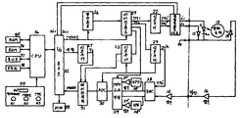
제5도는 본 발명의 일실시예의 개략블록도.5 is a schematic block diagram of one embodiment of the present invention.
제6도는 피측정물의 소정광로내를 통과한 후에 있어서의 파장 λ1, λ2의 광량을 검출하기 위한 타이밍도.6 is a timing chart for detecting the amount of light having wavelengths λ1 and λ2 after passing through a predetermined optical path of a measurement target.
제7도는 제1도에 도시한 RAM에 기억되는 데이터를 표시한 도면.FIG. 7 is a diagram showing data stored in the RAM shown in FIG.
제8a도 내지 제8c도는 본 발명의 일실시예의 구체적인 동작을 설명하기 위한 순서도로서, 제8a도는 데이터 샘플서브루우틴을 표시하고, 제8b도는 캘리브레이션 모우드를 표시하고, 제8c도는 측정모우드를 표시한 도면.8A to 8C are flowcharts for explaining a specific operation of an embodiment of the present invention. FIG. 8A shows a data sample subroutine, FIG. 8B shows a calibration mode, and FIG. 8C shows a measurement mode. One drawing.
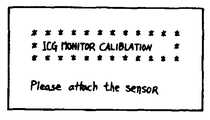
제9도 내지 제12도는 제5도에 표시한 표시부의 표시예를 도시한 도면.9 to 12 show examples of displays on the display unit shown in FIG.
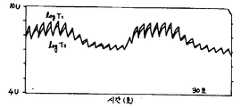
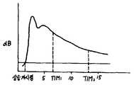
제13도는 본 발명에 의해서 측정되는 특정색소의 소실곡선의 일예를 표시한 도면.13 is a view showing an example of the disappearance curve of a specific pigment measured by the present invention.
* 도면의 주요부분에 대한 부호의 설명* Explanation of symbols for main parts of the drawings
10 : 센서부 11 : 제1광원10: sensor unit 11: first light source
12 : 제2광원 13 : 수광소자12 second light source 13 light receiving element
14 : 프리앰프 15 : 앰프14: preamp 15: amplifier
20 : 측정처리부 21 : 정(定) 전류회로20
23 : 타이밍회로 24 : 클록발생부23: timing circuit 24: clock generator
28 : 샘플호울드회로 29 : 멀티플렉서28: sample holder circuit 29: multiplexer
30 : A/D변환기 31 : 데이터래치회로30: A / D converter 31: Data latch circuit
32 : I/O포오트 33 : 버저32: I / O port 33: Buzzer
34 : CPU 35 : RAM34: CPU 35: RAM
36 : ROM 37 : 표시부36: ROM 37: display unit
38 : 프린터 39 : 조작부38: printer 39: control panel
40 : 경보 LED 41 : 캘리브레이션키이40: alarm LED 41: calibration key
42 : 스타아트키이 43 : 프린트키이42: Star Art Key 43: Print Key
본 발명은 간기능검사장치에 관한 것으로서, 특히, 선택적으로 간장에서만 섭취, 배설되는 특정색소를 혈액속에 주입해서, 혈액속의 특정색소농도에 상관하는 값을 연산하고, 간기능검사장치에 관한 것이다.BACKGROUND OF THE
간 기능을 검사진단하기 위한 종래의 혈장소실률과 정체율의 측정법은, 특정의 색소로서 인도시아닌그리인(이하, ICG라 부름)을 사용해서 채혈에 의해 측정하는 방법이 사용되고 있었다.As a conventional method for measuring the blood loss rate and the retention rate for examining and diagnosing liver function, a method of measuring by blood collection using indocianingrin (hereinafter referred to as ICG) as a specific pigment has been used.
이 방법에 의하면, ICG를 피검자에 정주(靜注)한 후, 주사후 5분, 10분, 15분의 3회 채혈하고, 혈병(血餠)의 응축을 기다려서 혈청을 분리하고, 분광광도계를 사용하여, 파장 805nm에 있어서의 흡광도를 측정하고, 미리 얻고 있던 검량선(ICG 혈중대응농도 V, S, 흡광도)으로부터 5분, 10분, 15분 후의 혈청속의 ICG농도를 구하여, 이 농도변화로부터 혈장소실률과 정체율을 산출하는 것이다.According to this method, after ICG is settled in a subject, blood is collected 3 times, 5 minutes, 10 minutes, and 15 minutes after injection, and serum is separated by condensation of a blood clot, and a spectrophotometer is used. The absorbance at wavelength 805 nm was measured, and the ICG concentration in serum after 5 minutes, 10 minutes, and 15 minutes was obtained from the calibration curve (ICG blood response concentrations V, S, and absorbance) previously obtained, and the plasma was changed from this concentration change. It is to calculate the loss rate and stagnation rate.
또, 이 측정을, 채혈하는 일없이도 체표(體表)로부터 광을 조사하고, ICG의 흡광감도가 높은 파장과 감도가 거의 없는 파장의 생체로부터의 반사광량을 측정하고, 이 시간변화(색소소실곡선)로부터 혈장소실률과 정체율을 구하는 방법이 일본국 특공소 60-58649호 공보에서 제안되고 있었다. 이 제안된 방법에 의하면, 체표에 의해 광을 조사하고, ICG의 흡광감도가 높은 파장과 감도가 거의 없는 파장의 생체로부터의 투과 또는 반사된 광량을 측정하고, 이 시간변화(색소소실곡선)로부터 혈장소실률과 정체율을 구한다.In addition, this measurement irradiates light from the body surface without collecting blood, measures the amount of reflected light from the living body at a wavelength having a high absorption sensitivity of ICG and a wavelength having little sensitivity, and then changes this time (pigment loss). The method of calculating the plasma loss rate and the retention rate from the Japanese Patent Application Publication No. 60-58649 has been proposed. According to this proposed method, light is irradiated by the body surface, and the amount of transmitted or reflected light from a living body having a wavelength of high absorption sensitivity of ICG and a wavelength having little sensitivity is measured, and from this time variation (pigment loss curve) Find the plasma loss rate and retention rate.
또, 일본국 특개소 64-17630호 공보에 있어서도, 체표에 의해 광을 조사하여, ICG의 흡광량을 측정하고, 이 시간변화(색소소실곡선)로부터 혈장소실률과 정체율을 구하는 장치를 개시하는 것으로서, 측정전에 캘리브레이션하므로서, 생체내의 혈액량의 변동을 없애도록(Cancel)한 것이다.In addition, Japanese Unexamined Patent Publication No. 64-17630 also discloses an apparatus for irradiating light with a body surface to measure the absorbance of ICG, and to determine the plasma loss rate and retention rate from this time variation (pigment loss curve). This is to cancel the fluctuation of blood volume in the living body by calibrating before measurement.
종래의 방법인 채혈법은, 주사후의 채혈시간을 정확하게 측정할 필요가 있다. 그러나, 실제의 검사에서는, 정밀도 좋게 측정되고 있지 않으며, 측정조작도 번잡하였다. 또, 채혈에 의한 피검자에의 정신적, 육체적 부담이 컸었다. 또, 혈장소실률을 ICG 주입량을 변화시켜서 수회 측정해서 구하는 Rmax 측정법은, 최근 한창 행하여지게 되고 있으나, 이 방법에서는, 수회의 채혈을 필요로 하여, 피검자의 부담은 한층 더 커진다고 하는 문제점이 있었다.In the conventional blood collection method, it is necessary to accurately measure the blood collection time after injection. However, in the actual inspection, the measurement was not performed with high accuracy, and the measurement operation was also complicated. Moreover, the mental and physical burden on the subject by blood collection was large. Moreover, the Rmax measuring method which measures and measures the plasma loss rate by changing ICG injection amount several times is performed in full swing in recent years, but this method requires the collection of several times, and there existed a problem that the burden of a test subject became much larger.
또, 상기한 일본국 특공소 60-58649호 공보나 일본국 특개소 61-162934호 공보에 개시되어 있는 채혈없이 측정하는 방법에서는, 실제로 센서를 생체에 장착하였을 경우, 혈관압박에 의한 혈류장해, 피측정물인 생체의 요동, 생체내의 맥동이나 생체내의 혈류량의 변화(예를 들면, 팔의 상하만으로 혈류량은 변화한다)등의 영향에 의해, 출력이 변동하여, 정확한 색소소실곡선을 얻을 수 없다.In addition, in the method of measuring without blood collection disclosed in Japanese Laid-Open Patent Publication No. 60-58649 or Japanese Laid-Open Publication No. 61-162934, when a sensor is actually mounted on a living body, blood flow problems due to vascular compression are The output fluctuates due to the fluctuation of the living body, the pulsation in the living body, the change in the blood flow in the living body (for example, the blood flow changes only by the upper and lower arms), and an accurate pigmentation curve cannot be obtained.
이 때문에, 이 곡선에 의해 얻어지는 혈장소실률과 정체율도 정확한 것이라고 할 수 없다.For this reason, the plasma loss rate and retention rate obtained by this curve cannot be said to be accurate either.
일본국 특개소 64-17630호 공보에 개시되어 있는 장치는, 측정전에 캘리브레이션을 행할 필요가 있기 때문에, 조작이 번잡하였다. 또, 생체내의 혈액량의 변동을 어느정도 없앨 수는 있으나, 반드시 충분하다고는 말할 수 없었다. 그것은, 이 캘리브레이션은, 특정색소의 주입직전에 행하는 것이 바람직하나, 실제상, 특정색소의 주입에는 시간이 소요되기 때문에, 모처럼의 캘리크레이션도 측정의 정밀도를 올리는데에는 한계가 있기 때문이다.Since the apparatus disclosed in Japanese Patent Laid-Open No. 64-17630 needs to be calibrated before the measurement, the operation is complicated. Moreover, although the fluctuation | variation of the blood volume in a living body can be eliminated to some extent, it cannot be said that it is necessarily enough. It is preferable that this calibration is performed immediately before the injection of a specific color. However, since the injection of a specific color takes time in practice, even a slight calibration has a limit in increasing the accuracy of the measurement.
그러므로, 본 발명의 주된 목적은, 센서의 생체장착시에 있어서의 혈류장해나 생체의 요동, 생체내의 맥동, 생체내의 혈류량의 변화의 인위구조(artifact)를 제거할 수 있어, 보다 한층 정확한 측정이 가능한 간기능검사장치를 제공하는 일이다.Therefore, the main object of the present invention is to eliminate blood flow disturbances, fluctuations of living organisms, pulsations in living organisms, and artifacts of changes in blood flow in living organisms. To provide a possible liver function test device.
본 발명은 간기능을 검사하기 위한 간기능검사장치로서, 생체조직의 혈액속에 투여되고 또한 간장에서 섭취 및 배설되는 특정의 색소에 흡광되는 파장의 제1광과, 흡광되지 않는 파장의 제2광을 상기 생체조직에 조사하는 광원수단, 상기 광원수단에 의해서 상기 생체 조직에 조사되고, 상기 생체조직으로부터 얻어지는 상기 제1 및 제2광에 대응하는 제1 및 제2의 광전변환기호를 출력하는 광전변환수단, 상기 광전변환수단으로부터의 상기 제1 및 제2의 광전변환출력을 샘플링하기 위한 샘플링수단, 상기 광전변환수단으로부터의 상기 제1 및 제2의 광전변환출력의 맥동성분만을 검출하기 위한 맥파검출수단, 상기 특정색소의 주입직전의 상기 맥파검출수단으로부터 얻은 제1 및 제2의 광전변환출력의 맥파성분의 강도 사이에 있어서의 직선회귀식의 계수 및 상기 샘플링수단에 의해서 샘플링된 상기 제1 및 제2의 광전변환신호와 상기 직선회귀식의 계수를 사용해서 베이스치를 결정하는 결정수단 및 상기 특정색소의 주입으로부터 소정시간동안에 있어서의 상기 샘플링수단의 샘플링신호출력과 상기 결정수단에 의해서 결정된 직선회귀식에 의거해서, 상기 혈액속의 특정색소농도에 상관하는 값을 연선하는 수단을 구비한 것을 특징으로 한다.BACKGROUND OF THE
본 발명의 보다 바람직한 태양으로서, 상기한 간기능검사장치로서, 상기 맥파검출수단은, 상기 제1 및 제2의 광전변환신호를 복수회 검출하기 위한 수단을 포함하고, 상기 직선회귀식의 계수를 결정하는 수단은, 상기 맥파검출수단에 의해서 복수회 검출된 상기 제1 및 제2의 광전변환출력의 맥파성분의 강도를 T1p, T2p로 하였을 때,As a more preferable aspect of the present invention, in the liver function test apparatus, the pulse wave detecting means includes means for detecting the first and second photoelectric conversion signals a plurality of times, and the linear regression coefficient is calculated. The means for determining is assuming that the intensity of the pulse wave components of the first and second photoelectric conversion outputs detected by the pulse wave detection means a plurality of times is T1 p, T2 p,

의 연산식에 따라서, 직선회귀분석을 행하여, 정수 A를 구하고, 상기 샘플링수단에 의해서 샘플링된 상기 제1 및 제2의 광전변환신호를 T1c, T2c로 하였을 때,When a linear regression analysis is performed to obtain the constant A and the first and second photoelectric conversion signals sampled by the sampling means are T1 c and T2 c.

의 연산식에 따라서, 베이스치 So'를 구하는 동시에 상기 복수회 샘플링된 상기 제1의 광전변환신호의 최대치를 T1o로서 구하는 수단을 포함하는 것이다.And means for obtaining the base value So 'and obtaining the maximum value of the first photoelectric conversion signal sampled a plurality of times as T1 o according to the equation
다른 보다 바람직한 태양으로서, 상기 연산수단은, 상기 샘플링된 제1 및 제2의 광전변환신호의 값을 T1, T2로 하였을 때, 상기 결정수단에 의해서 구하게 된 정수 A, So' 및 최대치 T1o에 의거해서, 상기 특정색소농도에 상관하는 값 Sg를 다음의 연산식에 따라서 연산하는 수단을 포함하는 것이다.As another more preferable aspect, the calculating means includes the constants A, So 'and maximum value T obtained by the determining means when the values of the sampled first and second photoelectric conversion signals are T1 and T2 . Based on1 o, a means for calculating the value Sg correlated with the specific pigment concentration according to the following formula is included.

본 발명의 다른 태양은, 구하여진 시뮬레이션함수의 계수에 의거해서, 특정색소의 혈장소실률 또는, 혹은 동시에 특정색소의 소정시간에 있어서의 정체율을 구하는 수단을 구비한다.According to another aspect of the present invention, there is provided a means for calculating the plasma loss rate of a specific pigment or the retention rate at a predetermined time at a time based on the coefficients of the obtained simulation function.
본 발명에 관한 간기능검사장치는, 생체조직내에 제1 및 제2의 광을 조사하고, 생체로부터 얻어지는 광에 대응하는 광전변환신호를 샘플링하고, 미리 특정색소주입직전에 측정한 캘리브레이션커어브로부터 생체내의 혈액변동을 제거하는 연산을 사용해서 특정색소의 혈중농도에 대응하는 값을 산출하고, 최소 2승법을 사용해서 특정색소의 혈중농도에 대응하는 값을 산출하고, 최소 2승법을 사용해서 2연산 결과의 시간변화에 있어서의 시뮬레이션커어브의 함수를 연산하고, 그 함수에 의거해서, 색소농도에 상관하는 값을 구하는것이며, 더욱 바람직하게는, 특정색소의 혈장소실률 K 또는, 혹은 동시에 T분 정체율 R%를 구하도록 하였으므로, 체혈의 필요가 전혀 없게 되고, 피검자의 부담을 특정색소의 정주만으로 할 수 있어, 피검자의 정신적, 육체적 부담을 대폭적으로 경감할 수 있다. 또, 센서의 생체장착시에 있어서의 혈류장해나 생체의 요동, 맥동 등의 인위구조를 제거할 수 있다.The liver function test apparatus according to the present invention is characterized by irradiating first and second light into a living tissue, sampling a photoelectric conversion signal corresponding to the light obtained from the living body, and measuring the calibration curve before measurement of a specific pigment in advance. Using a calculation to remove blood fluctuations in vivo, a value corresponding to the blood concentration of a specific pigment is calculated, a value corresponding to the blood concentration of a specific pigment is calculated using the least-squares method, and 2 It is to calculate a function of the simulation curve in the time variation of the calculation result, and to calculate a value correlated with the pigment concentration based on the function. More preferably, the plasma loss rate K of the specific pigment, or T at the same time. Since the stagnation rate R% was obtained, there was no need for a bodily blood, and the burden of the test subject could be made only by a specific color settling, and the mental and physical condition of the test subject We can greatly reduce burden. In addition, it is possible to remove artificial structures such as blood flow disturbances, fluctuations of the living body, and pulsation when the sensor is mounted.
제1도-제4도는 본 발명의 원리를 설명하기 위한 도면이다.1 to 4 are diagrams for explaining the principle of the present invention.
특정색소에 크게 흡광되는 파장 λ1과 흡수되지 않는 파장 λ2의 생체조직에의 입사광량을 I1, I2로 하고, 생체조직의 소정의 광로내를 통과한 후의 광량을 각각 T1, T2로 한다. 특정색소를 주입하였을 때의 I1, I2, T1및 T2의 관계는 이하와 같이 된다.The amount of light incident on the biological tissue at the wavelength λ1 that is largely absorbed by the specific pigment and the wavelength λ2 not absorbed is set to I1 and I2 , and the amounts of light after passing through the predetermined optical path of the biological tissue are T1 and T, respectively.2 The relationship between I1 , I2 , T1, and T2 when a specific pigment is injected is as follows.


각 계수나 변수는 제1도에 표시되어 있다. 여기서, f1, f2는 파장 λ1, λ2에 있어서의 혈액의 특성에 의해 결정되는 함수이다.Each coefficient or variable is shown in FIG. Here, f1, f2, is a function that is determined by the characteristics of blood at the wavelengths λ1, λ2.
한편, 특정색소를 주입하기전의 I1, I2, T1및 T2의 관계는On the other hand, the relationship between I1 , I2 , T1 and T2 before injecting a specific pigment


로 된다.It becomes
여기서, T1, T2의 맥동성분만을 검출하면, ③,④식은,Here, if only the pulsating components of T1 and T2 are detected,
Δlog I1/T1=f1(Cb, ΔVb)Δlog I1 / T1 = f1 (Cb, ΔVb)
Δlog I2/T2=f2(Cb, ΔVb)Δlog I2 / T2 = f2 (Cb, ΔVb)
로 되며, 이 관계는, 제2도와 같이 측정되고, 제3도에 표시한 바와같이 선형의 관계가 된다. 이것은, 센서를 생체에 장착하여, 생체내의 혈액량을 변동시켰을 때의 데이터이다. 이 선형성(linearity)은 재형성이 있고, 또한 개체차(個體差)가 없는 것을 확인하고 있다. 고로 ③, ④식은,This relationship is measured as shown in FIG. 2 and becomes a linear relationship as shown in FIG. This is data when the sensor is mounted on a living body and the blood volume in the living body is varied. This linearity confirms that there is remodeling and there is no individual difference. So, ③ and ④ are

로 된다. 즉,It becomes In other words,

로 표시된다.Is displayed.
여기서, 특정색소주입전의 ③, ④식에 있어서도 변화하는 것은 혈액이 주된 성분이기 때문에,Here, the change in

로 할 수 있다.You can do
다음에, 특정색소를 주입한 후의 ①, ②식을 사용해서,Next, using the

을 구하면,If you find,

여기서, ⑥식을 사용하면,Here, using ⑥,

로 된다.It becomes
또, 특정색소가 주입되기전의 S'o를,
고로, 제3도를 생체캘리브레이션커어브로서 사용하면, S의 신호가 얻어지는 것을 알 수 있다.Therefore, it can be seen that the signal of S is obtained by using FIG. 3 as the biocalibration curve.
그러나, S로는 Kg는 일정한, Vb에 의한 변동이 있고, 정확한 Cg를 얻을 수 없다. 즉, 생체내의 혈액량에 의해 영향을 받는다.However, with S, Kg is constant and there is a variation by Vb, and accurate Cg cannot be obtained. That is, it is affected by the blood volume in vivo.
그래서, 제4도에 있어서,

다음에, ⑨식의 Vb는

로 생각할 수 있다.You can think of it as
고로, Cg에 대응하는 신호 Sg는 ⑦및 ⑩식에 의해,Therefore, the signal Sg corresponding to Cg is expressed by? And?

를 얻게 된다.You get
이하, 본 발명의 실시예에 대하여 첨부도면을 참조하여 상세히 설명한다.Hereinafter, exemplary embodiments of the present invention will be described in detail with reference to the accompanying drawings.
제5도는 본 발명의 일실시예의 개략블록도이다.5 is a schematic block diagram of one embodiment of the present invention.
제5도에 있어서, 간기능검사장치는 센서부(10)과 측정처리부(20)으로 구성되어 있다. 센서부(10)는, 제1광원(11)과 제2광원(12)와 수광소자(13)과 프리앰프(14)를 포함한다.5, the liver function test apparatus is composed of a
제1광원(11)과 제2광원(12)는, 특정색소의 흡광도가 큰 파장 λ1과 흡광도가 없는 파장 λ2의 광펄스를 각각 발생한다.The first light source 11 and the second
수광소자(13)는, 광원(11) 및 (12)로부터 생체조직(15)에 조사되고, 소정의 광로내를 통과한 광을 수광한다. 또한 광원(11) 및 (12)는, 각각 교호로 펄스동작으로 광을 발광하도록, 측정처리부(20)에 의해서 구동된다.The light receiving element 13 is irradiated to the
측정처리부(20)은, 연산수단으로서의 CPU(34)를 포함한다. CPU(34)는 I/O 포오트(32)를 통해서, 스타아트신호를 발진회로(24)와 타이밍회로(23)에 인가한다. 발진회로(24)는 상시 소정의 블록을 발진하고 있다.The
이 블록과 상기 스타아트신호를 사용해서, 타이밍회로(23)과 디코우더 1(22)를 통해서, 정전류회로(21)로부터 제1광원(11)과 제2광원(12)에 정전류(定電流)il과 i2를 제6도의 타이밍 TMl"과 TMl"로 인가한다.Using this block and the star art signal, a constant current is established from the constant
제1광원(11)과 제2광원(12)에 의해 발광된 광은, 생체조직(15)의 소정로 광통내를 통과해서, 수광소자(13)에 입사된다. 수광소자(13)으로부터 발생한 전류는, 프리엠프(14)에 의해 전류-전압 변환과 증폭을 받는다.The light emitted by the first light source 11 and the second
측정처리부(20)내에 있는 앰프(16)에 의해 소정의 범위내에 증폭되어, 제6도의 VPD와 같은 출력을 얻을 수 있는 이 신호는, 타이밍회로(23)과 디코우더 2(25)에 의해 발생한 제6도에 표시한 타이밍 TM2'에 의해 구동되는 샘플호울드회로(SHC)(28)에 의해, 샘플호울드된다.This signal, which is amplified within a predetermined range by the
제6도에 표시한 전압 T1과 T2가 유지되고, 멀티플렉서(MPX)(25)와 AD 변환기(ADC)(30)과 데이터래치회로(31)에 의해 각각 디지탈신호를 변환된후, 데이터래치된다. 이때, 멀티플랙서(25)와 AD변환기(30)과 데이터래치회로(31)의 타이밍은, 타이밍회로(23)과 디코우더 2(26)에 의해 제어된다.The voltages T1 and T2 shown in FIG. 6 are maintained, and the digital signals are converted by the multiplexer (MPX) 25, the AD converter (ADC) 30, and the
래치된 데이터는,
또, 샘플호울드된 신호는, 제5도에 표시한 바와같이, 고대역통과 필터(HPF)와 증폭기를 사용해서 느린 성분을 제외하고, 맥파성분만을 뽑아내고 있다. 이것은 T1및 T2다같이 행하여 지며, 각각 앰프(16)에 의해서 증축한후, 멀티플렉서(25)에 의해 상기한 바와 같이 디지탈신호로서 RAM(35)에 집어넣게 된다.In addition, as shown in FIG. 5, the sample-bound signal extracts only the pulse wave component except for the slow component using a high pass filter (HPF) and an amplifier. This is done in combination with T1 and T2 , and then expanded by the
RAM(35)는 후술하는 제7도에 표시한 바와같은 데이터를 기억하는 것으로서, ROM(36)은 후술하는 제8a도-제8c도에 표시한 순서도에 의거한 프로그램을 기억한다. 표시부(37)은 후술하는 제9도-제12도에 표시한 바와같은 데이터를 표시한다. 프린터(38)은 간기능검사결과를 프린트하는 것이다.The RAM 35 stores data as shown in FIG. 7 to be described later. The
조작부(39)는 경로 LED(40)과 캘리브레이션키이(41)과 스타아트키이(42)와 프린트키이(43)을 포함한다. 경보 LED(40)은, 검사 결과의 신뢰도가 작을 경우에 경보를 표시하는 것이며, 캘리브레이션키이(41)은 캘리브레이션모우드를 설정하기 위한 것이며, 스타아트키이(42)는 측정모우드의 개시를 지령하는 것이며, 프린트키이(43)은 검사결과의 프린트아우트를 지령하는 것이다.The
제8a도-제8c도는 본 발명의 일실시예의 구체적인 동작을 설명하기 위한 순서도이다. 제7도는 제5도에 표시한 RAM(35)에 기억되는 데이터를 표시한 도면이며, 제9도 내지 제12도는 제5도에 표시한 표시부의 표시예를 도시한 도면이다.8A to 8C are flowcharts for describing a specific operation of an embodiment of the present invention. FIG. 7 is a diagram showing data stored in the RAM 35 shown in FIG. 5, and FIGS. 9 to 12 are views showing display examples of the display section shown in FIG.
다음에 제5도, 제6도 내지 제13도를 참조해서 본 발명의 일실시예의 구체적인 동작을 설명한다.Next, the specific operation of one embodiment of the present invention will be described with reference to FIGS. 5 and 6 to 13.
먼저, 제8도에 표시한 스텝(도면에서는 SP로 약칭함) SP11내지 SP16은, 1짝의 파장 λ1, λ2의 피측정물통과후의 광의 광량을 샘플해서, RAM(35)에 기억하는 것이다. 즉, CPU(34)는, SP11에 있어서 제5도에 표시한 라인으로부터 I/O 포오트(23)을 개재해서, 스타아트신호를 출력한다. 스타아트신호에 의해 상기한 바와같이 T1, T2의 값이 데이터래치된다. SP12에서는 래치될때까지 대기하고 있다.First, the steps shown in FIG. 8 (abbreviated as SP in the drawing) SP11 to SP16 sample the amount of light after passing through the measured object having a pair of wavelengths λ1 and λ2 to the RAM 35. To remember. That is, the
다음에, SP13에서는 CPU(34)는, 제5도에 표시한 선택라인(select line)에 I/O 포오트를 개재해서 선택신호를 출력하고, SP14에서 먼저 T1의 데이터를 I/O 포오트(32)를 개재해서 판독해넣고, 제6도에 표시한 RAM(35)의 기억영역(8'a1) 에 메모리된다.Next, SP13 in the CPU (34), the selection shown in FIG. 5 line via a I / O port oats in (select line) outputs a selection signal, and in the SP14, first I data of T1 / It reads in through the O-
마찬가지로, SP15, SP16에 있어서, T2의 데이터가 RAM(35)의 기억영역(8a2)에 메모리된다.Similarly, in SP15 and SP16 , the data of T2 is stored in the storage area 8a2 of the RAM 35.
상기 스텝 SP16에 있어서의 연산을 완료하면 CPU(34)는 원래의 스텝으로 리터언한다.After completing the operation in the above-mentioned step SP16 CPU (34) is frozen liter to the previous step.
이에 대해서는 캘리브레이션모우드를 표시한 제8b도에서 설명한다.This is illustrated in FIG. 8B in which the calibration mode is indicated.
이 캘리브레이션모우드는, 후술하는 제8c도에 표시한 측정 모우드의 동작전에 개시된다. 스텝 SP21에 있어서, CPU(34)는 표시부(37)에 캘리브레이션 모우드를 표시시킨다. 이 표시에 대해서는, 예를들면, 제9도에 표시한 바와같이, 캘리브레이션모우드로 들어가 있는 것을 표시하는 동시에, 센서부(10)의 장착을 지시하는 것이다. 이 지시에 따라서, 측정자는 센서부(10)을 피측정물(13)에 장착한다.This calibration mode is started before the operation of the measurement mode shown in FIG. 8C to be described later. In step SP21 , the
그후, CPU(34)는 스텝 SP22에 있어서, 캘리브레이션키이(41)이 조작될때까지 대기한다. 캘리브레이션키이(41)이 조작되면, CPU(34)는 스텝 SP23으로 나아가, 상기한 제8a도에 표시한 데이터샘플의 서브루우틴을 실행한다.Then, CPU (34), the processing awaits until at the step SP22, a calibration key 41 is operated. When the calibration key 41 is operated, CPU (34) is further to the step SP23, and executes the sub Lou tin of data samples shown in the above-described first 8a Fig.
다음에, SP23에서 판독해 넣은 T1, T2가 RAM(35)내의 (8b1), (8b2)에 있는 TMAX와 TMIN의 범위에 들어가도록, 제5도에서 CPU(34)는 Si1, Si2라인을 사용해서 정전류회로(21)을 제어한다. 그리고, 이 Si1, Si2의 전류설정치를 RAM 내의 (8c1), (8c2)에 메모리한다.Next, the
이후, Si1, Si2의 전류가 상시 광원(11), (12)에 흐른다.Thereafter, currents of Si1 and Si2 flow through the
이어서, SP25에서는 버저소리를 울리게하여, 파우어설정이 종료된 것을 알린후, 측정모우드로 이행한다.Subsequently, in SP25 , a buzzer sounds, notifying that the power setting is completed, and then proceeding to the measurement mode.
다음에, 제8c도를 참조해서, 측정모우드에 대해서 설명한다.Next, the measurement mode will be described with reference to FIG. 8C.
JP26-SP25는, 상기한 생체캘리브레이션을 행하는 순서도이다. 구체적으로는, SP26, SP27에서 맥파신호로 변환된 CT1, CT2의 값을 각각 n회 샘플해서, CT1(1)-CT1(n)을 (8d1)-(8dn), CT2(1)-CT2(n)을 (8e1)-(8en)에 메모리 한다.JP26- SP25 is a flowchart for performing the above-described biocalibration. Specifically, the values of CT1 and CT2 converted into pulse wave signals at SP26 and SP27 are sampled n times, and CT1 (1) -CT1 (n) is (8d1 )-(8dn ). , CT2 (1) -CT2 (n ) is stored in (8e1 )-(8en ).
다음의 SP28에서는, logCT1(I)과 logCT2(I)(I=1~n)에 대해서 2변수 통계계산을 행하고,In the next SP28 , two-variable statistical calculation is performed on logCT1 (I) and logCT2 (I) (I = 1 to n),
logCT1(I)=A·logCT2(I)logCT1 (I) = AlogCT2 (I)
의 A치와 상관계수 r1과 동시에 계측한 n개의 T1(I)과 T2(I)을 사용하고,Use of n T1 (I) and T2 (I) measured at the same time as the correlation coefficient r1, and A values, and

로부터 S'를, 그리고 T1(I)(I=1~n)의 최대치 T10를 구하고, 각각 RAM내의

이 표시에 대해서는, 예를들면, 제10도에 표시한 바와같이, 특정색소, 예를들면, IOG를 주입하는 것을 지시하는 표시가 행하여 진다. 이 표시에 따라서, 측정자는 특정색소를 피검자에 주입하기 위한 준비를 행한다. 다음에, CPU(34)는 스텝 SP42에 있어서, 스타아트키이(42)가 온될때까지 대기한다. 이 대기동안, SP26-29의 동작 즉 생체 캘리브레이션은, 반복행하여지고, 스타아트키이(42)가 눌러지는 직전의 캘리브레이션은, 반복행하여지고, 스타나트키이(42)가 눌러지는 직전의 캘리브레이션(A, r1, So', T10)이 RAM내의
스타아트키이(42)가 눌려지면, 그 직전의 캘리브레이션 데이터가 이후의 측정에 채용된다.When the star art key 42 is pressed, the calibration data immediately before that is adopted for subsequent measurement.
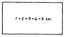
CPU(34)는 스타아트키이(42)가 조작된 것을 판별하면, 스텝 SP43에 있어서, 특정색소의 타이밍을 표시하는 동시에, 버저(33)에 의해서 경보소리를 알리게 된다.When the
이것은, 예를 들면, 제11도와 같이, 1≥2≥3≥4≥5와 같이 표시되고, 측저자는 "5"가 표시되었을 때, 특정색소의 주입을 행한다. 또, CPU(34)는 표시가 "1", "2", "3", "4"일때 제1의 소리를 버저로부터 발생시키고, "5"가 표시되었을때는, 버저(33)으로부터 달라진 소리를 발생시킨다.For example, as shown in Fig. 11, 1? 2? 3? 4? 5 is displayed, and the side author performs injection of a specific color when? 5? Is displayed. In addition, the
측정자는 이 소리나 표시가 발생하였을때, 특정색소의 주입을 행한다. CPU(34)는 스텝 SP44에 있어서, 타이머의 초기치로서 "0"을 설정한다.The measurer injects a specific pigment when this sound or indication occurs. CPU (34) is set to "0" as the initial value of the timer, in step SP44.
다음에, CPU(34)는 스텝 SP45에 있어서, 상기한 제8a도에서 설명한 서브루우틴인 데이터샘플프로그램을 실행한다. 그러자, RAM(24)의 기억영역(8a1) 내지 (8a2)에 T1내지 T2로서 각각 기억된다. 스텝 SP46에 있어서, CPU(34)는 상기한 제8b도에서 설명한 캘리브레이션모우드로 RAM(35)의 기억영역


이 Cg(I)의 값은, 스텝 SP46에 있어서, 예를 들면, 제12도에 표시한 바와 같은 태양으로 표시부(37)에 표시된다. 제12도에 있어서, 횡축은 특정색소주입후로부터의 경과시간을 표시하고 종축은 Cg(I)의 값이다. 여기서, 특정색소의 소실곡선의 샘플링수를 m로 하면, I는 1 내지 n의 정수(整數)이며, 소실곡선의 측정시간을 Ts로 하면, 1호의 샘플링타임은 ITM=Ts/(m-1)이다. 물론 I=1의 경우는, 특정색소의 주입시에 일치한다. 스텝 SP47에 있어서, CPU(34)는, 이 샘프링타임 ITM의 동안 대기한다.The value of the Cg (I) is, in step SP46, for example, 12 is shown in one embodiment as a
이 대기시간을 경과하면, CPU(34)는 스텝 SP48에 있어서, i가 n보다도 큰지 안큰지를 판별한다. i가 n보다도 클 경우는 스템 SP45로 나아가나, 작을 경우에는, 다시 스텝 SP45로 되돌아가, 반복하여 샘플링을 행한다. 여기서, RAM(24)의 기억열역(8g1) 내지 8gm에 기억되어 있는 데이터 Cg(I)는, 예를들면, 제13도에 표시한 바와같은 특정색소의 소실곡선을 그리나, 이 상승 시작점을 검출하고, 스텝 SP45에 있어서, 그앞의 데어터를 베이스 라인으로 해서, 각 Cg(I)로부터 감산하고, 재차기억영역(8g1) 내지 (8gm)에 기억한다. 물론, 측정정밀도를 높이기 위하여 스텝 SP45의 T1내지 T2는 K회의 평균치라도 된다.If the limit is exceeded the standby time, the CPU (34) determines, i is greater than n not large at the step SP48. If i is larger than n, the flow advances to the stem SP45 , and if it is small, the flow returns to step SP45 again and sampling is repeated. Here, the data Cg (I) stored in the storage train regions 8g1 to 8gm of the RAM 24, for example, draws a disappearance curve of a specific color as shown in FIG. and, in step SP45, to the deeoteo of geuap as a baseline, and is subtracted from each of Cg (I), is again stored in the storage area (8g1) to (8gm). Of course, T1 to T2 in step SP45 may be an average value of K times in order to increase the measurement accuracy.
다음에, CPU(34)는 스텝 SP51에 있어서, 기억영역(8g1) 내지 (8gm)에 기억된 Cg(I)의 데이터중, 시간 T1내지 T2(0<T1<T2<T3)동안의 데이터에 대해서,Next, CPU (34) is, in step SP51, the storage area (8g1) to of the data of the Cg (I) stored in the (8gm), time T1 toT 2 (0 <T 1 < T 2 <T3 ) For data during
Cg(t)=CgO·e8.tCg (t) = CgOe8.t
t=Ts/(n-1)(분)t = Ts / (n-1) (minutes)
의 시뮬레이션커어브에 의해서 최소 2승법을 사용해서, 정수 A, B를 구한다.The constants A and B are found by using the least square method with the simulation curve of.
다음에, CPU(34)는 스텝 SP(52)에 있어서 혈장소실률 K=-B, T분 정체을 R%≡eBT의 연산을 행하여, K, R을 구한다. 그리고, 구한 K, R을 RAM(35)의 기억영역(8j1), (8j2)에 각각 기억시킨다. 이때, CPU(34)는 최소 2승법에서의 상관계수 r2를 연산하고, 연산한 상관계수 r2를 RAM(35)의 기억영역(8j3)에 기억하게 된다. 또, CPU(34)는, 이때에 버저(14)로부터 종료 버저소리를 발생시킨다.Next, in step SP52, the
또, CPU(34)는 K의 값과 R%의 값을, 예를들면, 제12도에 표시한 바와같은 태양으로 표시부(37)에 표시하게 한다. 다음에, CPU(34)는 스텝 SP53에 있어서, 상관계수 r2가, 예를 들면, -0.95보다도 작은지 안작은지를 판별한다. 이것은, 상관계수 r2가 -1에 가까울수록 상관이 좋기 때문에, 그 상관도를 체크하는 것이다. 다만, -0.95라고 하는 값은, 0 내지 -1의 사이의 값으로서, 잠정적이며, 물론 -1에 가까울수록 장치의 신뢰성이 향상된다.In addition, the
여기서, 상관계수 rχ
그리고 CPU(34)는 스텝 SP55에 있어서, 프린트키이(43)이 조작되어 있는지 여부를 판별하고, 조작되어 있으면, 프린터(38)에 의해서 K의 값과 R%의 값을 프린트시킨다.And the CPU (34) is, in step SP55, if the print key 43 is the determination whether the operation, and operation, the print values to the value of the R% of K by the
또, 만약 필요하다면, RAM(35)의 기억영역(8g1) 내지 (8gn)에 기억되어 있는 Cg(I)의 특성색소 소실곡선도 프린트시켜서, 상기한 제8b도에 표시한 캘리브레이션모우드를 이행한다.If necessary, the characteristic color disappearance curve of Cg (I) stored in the storage areas 8g1 to 8gn of the RAM 35 is also printed, and the calibration mode shown in FIG. 8B is executed. .
또, 스텝 SP55에 있어서, 프린트키이(43)의 조작안되어 있는 것을 판별하였을 때에도 캘리브레이션모우드로 이행한다.Further, the process proceeds to the calibration Modal even when, in step SP55, determines that the operation of the print key in less than 43.
또, 스텝 SP55에 있어서, 프린트 키이(43)의 조작되어 있는 않는 것을 판별하였을 때에도, 캘리브레이션모우드로 이행한다.In addition, even when determining that the operation is in the step SP55, the print key 43, the process proceeds to the calibration modal.
또한, 본 발명에 의해서 얻어진 K의 값을 이용해서, 여러가지의 ICG 투여량의 K의 값을 구하여 산술하는 RMAX를 측정하는 장치에도 확장할 수 있다.Moreover, it can be extended also to the apparatus which measures RMAX which calculates and calculates the value of K of various ICG doses using the value of K obtained by this invention.
이상과 같이, 본 발명에 의하면, 특정색소에 크게 흡수되는 파장의 광펄스와 흡수되지 않는 파장의 광펄스를 소정의 레벨로 생체조직에 조사하여, 생체조직의 소정의 광로내를 통과한 광펄스를 검지하여, 그 출력에 의거해서 생체 캘리브레이션을 행하고, 그 계수를 사용하여, 특정색소가 주입된 후에, 주입시부터 소정시간까지의 수광출력에 의거해서, 소정의 연산식에 따라서 특정색소의 혈장소실률과 정체율을 구하여 출력하도록 하였으므로, 정확하게 특정색소의 소실곡선의 시간관리가 가능해지고, 정확한 데이터를 얻을 수 있다.As described above, according to the present invention, an optical pulse of a wavelength that is largely absorbed by a specific pigment and an optical pulse of a wavelength that is not absorbed are irradiated to the biological tissue at a predetermined level, and the optical pulse passed through the predetermined optical path of the biological tissue. Is detected, and bio-calibration is performed based on the output, and after the specific pigment is injected using the coefficient, the plasma of the specific pigment is determined according to a predetermined formula based on the light receiving output from the time of injection to the predetermined time. Since the loss rate and the retention rate are calculated and outputted, accurate time management of the disappearance curve of a specific color can be obtained and accurate data can be obtained.
또, 종래의 채혈법에 의한 몇점의 샘플이 아니고, 소실곡선의 다수의 데이터로부터 혈장소실률이나 정체율을 구할 수 있다.In addition, the plasma loss rate and the retention rate can be obtained from a large number of data of the disappearance curve instead of a few samples by the conventional blood collection method.
또, 종래의 ICG 주입량을 변화시켜서, 몇번 측정해서, 혈장소실률이나 정제율을 구하는 검사법에 비해서, 보다 측정법을 간략화 할 수 있다.Moreover, the measurement method can be simplified more than the inspection method which changes a conventional ICG injection amount, measures several times, and calculates a plasma loss rate and a purification rate.
또, 종래 문제가 되고 있던 센서의 생체장착시에 있어서의 혈류장해나 생체의 동요, 생체내의 맥동이나 생체내의 혈류량의 변화의 인위 구조도 제거할 수 있어, 정확한 측정이 가능하게 되었다. 또한, 캘리브레이션을 측정의 직전에 행하므로, 더한층 정밀도가 향상된다. 이 때문에, 무침습(無侵濕)으로 생체내의 색소를 측정하는 분야전반에 이용하면 효과적이다.In addition, the artificial structure of blood flow disturbance and fluctuation of the living body, fluctuations in the living body and changes in the blood flow in the living body at the time of mounting the sensor, which has become a problem in the past, can be eliminated, thereby enabling accurate measurement. Moreover, since calibration is performed just before a measurement, further precision improves. For this reason, it is effective when used for the whole field | area which measures the pigment | dye in a living body by non-invasiveness.
Claims (1)
Translated fromKoreanApplications Claiming Priority (2)
| Application Number | Priority Date | Filing Date | Title |
|---|---|---|---|
| JP1-132345 | 1989-05-24 | ||
| JP1132345AJPH02309929A (en) | 1989-05-24 | 1989-05-24 | Liver function testing device |
Publications (2)
| Publication Number | Publication Date |
|---|---|
| KR900017550A KR900017550A (en) | 1990-12-19 |
| KR930010545B1true KR930010545B1 (en) | 1993-10-28 |
Family
ID=15079173
Family Applications (1)
| Application Number | Title | Priority Date | Filing Date |
|---|---|---|---|
| KR1019900007493AExpired - Fee RelatedKR930010545B1 (en) | 1989-05-24 | 1990-05-24 | Apparatus for inspecting fuction of liver |
Country Status (7)
| Country | Link |
|---|---|
| US (1) | US5178141A (en) |
| EP (1) | EP0399482B1 (en) |
| JP (1) | JPH02309929A (en) |
| KR (1) | KR930010545B1 (en) |
| CN (1) | CN1025452C (en) |
| CA (1) | CA2017413A1 (en) |
| DE (1) | DE69015694T2 (en) |
Families Citing this family (16)
| Publication number | Priority date | Publication date | Assignee | Title |
|---|---|---|---|---|
| US5337745A (en)* | 1992-03-10 | 1994-08-16 | Benaron David A | Device and method for in vivo qualitative or quantative measurement of blood chromophore concentration using blood pulse spectrophotometry |
| JP3270917B2 (en)* | 1994-06-02 | 2002-04-02 | 日本光電工業株式会社 | Oxygen saturation measuring device, blood light absorbing substance concentration measuring device, and biological signal processing method |
| US6280703B1 (en) | 1997-03-13 | 2001-08-28 | Mallinckrodt Inc. | Simultaneous multimodal measurement of physiological function |
| US6228344B1 (en) | 1997-03-13 | 2001-05-08 | Mallinckrodt Inc. | Method of measuring physiological function |
| ES2220105T3 (en)* | 1998-07-01 | 2004-12-01 | Andreas Prof. Dr. Med. Hoeft | DETERMINATION OF HEPATIC FUNCTION THROUGH A DISASSEMBLY RATE OF PLASMA. |
| US6339714B1 (en)* | 1999-09-13 | 2002-01-15 | Bo Chen | Apparatus and method for measuring concentrations of a dye in a living organism |
| US6519485B2 (en)* | 2000-12-13 | 2003-02-11 | The General Hospital Corporation | Minimally invasive system for assessment of organ function |
| DE60127810T2 (en) | 2001-04-27 | 2007-12-27 | CSEM Centre Suisse d`Electronique et de Microtechnique S.A. - Recherche et Développement | Time-keeping device with automatic time correction and method for time correction of such a device |
| US7074190B2 (en)* | 2002-10-09 | 2006-07-11 | Industrial Technology Research Institute | Non-invasive apparatus system for monitoring drug hepatoxicity and uses thereof |
| JP5115855B2 (en)* | 2008-06-19 | 2013-01-09 | 日本光電工業株式会社 | Pulse oximetry and pulse oximeter |
| ES2732832T3 (en) | 2010-07-30 | 2019-11-26 | Smartdyelivery Gmbh | Measurement procedure to determine a function of an organ |
| US8951781B2 (en)* | 2011-01-10 | 2015-02-10 | Illumina, Inc. | Systems, methods, and apparatuses to image a sample for biological or chemical analysis |
| CN102488525B (en)* | 2011-12-14 | 2014-04-16 | 吉林大学 | Hepatic functional reserve detector capable of removing blood oxygen fluctuation interference |
| CN102551670A (en)* | 2011-12-23 | 2012-07-11 | 北京华亘安邦科技有限公司 | Liver reserving function analyzer |
| CN107072505B (en) | 2014-04-05 | 2021-03-12 | 手术感应设备公司 | Devices, systems and methods for mapping of tissue oxygenation |
| CN104688234A (en)* | 2015-03-17 | 2015-06-10 | 吉林大学 | Noninvasive and disturbance-resistant detection method for ICG pigment concentration spectrum |
Family Cites Families (7)
| Publication number | Priority date | Publication date | Assignee | Title |
|---|---|---|---|---|
| GB1095114A (en)* | 1963-12-09 | 1967-12-13 | Atlas Werke Ag | Apparatus for the measurement of dye dilution in blood |
| US4017192A (en)* | 1975-02-06 | 1977-04-12 | Neotec Corporation | Optical analysis of biomedical specimens |
| US4602641A (en)* | 1983-08-15 | 1986-07-29 | The Regents Of The University Of California | Method and apparatus for NMR detection and imaging of flowing fluid nuclei |
| IL84356A (en)* | 1986-11-05 | 1991-08-16 | Sumitomo Electric Industries | Liver function testing apparatus |
| KR910002651B1 (en)* | 1987-11-13 | 1991-04-27 | 스미또모 덴끼 고교 가부시끼가이샤 | Liver function search instrument |
| JPH01129838A (en)* | 1987-11-13 | 1989-05-23 | Sumitomo Electric Ind Ltd | Liver function examination apparatus |
| JPH0657216B2 (en)* | 1988-09-14 | 1994-08-03 | 住友電気工業株式会社 | Liver function test device |
- 1989
- 1989-05-24JPJP1132345Apatent/JPH02309929A/enactivePending
- 1990
- 1990-05-21USUS07/526,885patent/US5178141A/ennot_activeExpired - Fee Related
- 1990-05-22EPEP90109734Apatent/EP0399482B1/ennot_activeExpired - Lifetime
- 1990-05-22DEDE69015694Tpatent/DE69015694T2/ennot_activeExpired - Fee Related
- 1990-05-23CNCN90104093Apatent/CN1025452C/ennot_activeExpired - Fee Related
- 1990-05-23CACA002017413Apatent/CA2017413A1/ennot_activeAbandoned
- 1990-05-24KRKR1019900007493Apatent/KR930010545B1/ennot_activeExpired - Fee Related
Also Published As
| Publication number | Publication date |
|---|---|
| CA2017413A1 (en) | 1990-11-24 |
| JPH02309929A (en) | 1990-12-25 |
| EP0399482A2 (en) | 1990-11-28 |
| CN1047571A (en) | 1990-12-05 |
| EP0399482A3 (en) | 1991-05-02 |
| KR900017550A (en) | 1990-12-19 |
| DE69015694T2 (en) | 1995-05-11 |
| CN1025452C (en) | 1994-07-13 |
| DE69015694D1 (en) | 1995-02-16 |
| EP0399482B1 (en) | 1995-01-04 |
| US5178141A (en) | 1993-01-12 |
Similar Documents
| Publication | Publication Date | Title |
|---|---|---|
| KR930010545B1 (en) | Apparatus for inspecting fuction of liver | |
| KR910008650B1 (en) | Liver function testing apparatus | |
| US4908762A (en) | Oximeter with system for testing transmission path | |
| JP2003194714A (en) | Measuring apparatus for blood amount in living-body tissue | |
| JPH11183377A (en) | Optical component meter | |
| CN117434040A (en) | Fluorescence measurement module for water quality multiparameter detection and measurement method thereof | |
| KR910002651B1 (en) | Liver function search instrument | |
| KR910002652B1 (en) | Liver function inspecting instrument | |
| EP0298122B1 (en) | Liver function inspection apparatus | |
| US5300769A (en) | Method and system of compensating for signal artifacts in a fiber-optic sensing system | |
| JP3524976B2 (en) | Concentration measuring device | |
| ITBS20070161A1 (en) | METHOD AND INSTRUMENT FOR THE NON-INVASIVE MEASUREMENT OF OXYGENATION / SATURATION OF A BIOLOGICAL FABRIC | |
| CN112485206B (en) | Correction method of contact type measuring device and percutaneous jaundice instrument | |
| JPH0534979B2 (en) | ||
| JPH0534978B2 (en) | ||
| JP2011506915A (en) | Method and measuring instrument for collecting spectroscopic examination signals from biological tissue | |
| Ntziachristos et al. | Accuracy limits in the determination of absolute optical properties using time-resolved NIR spectroscopy | |
| CN120577256A (en) | A device for detecting hemoglobin in peritoneal drainage fluid | |
| JPH0628655B2 (en) | Oxygen saturation measuring device | |
| JPH06181930A (en) | Organismic light measuring device | |
| JPH01129839A (en) | Liver function testing device | |
| JPH0351177B2 (en) | ||
| JPH04336057A (en) | Liver function testing device |
Legal Events
| Date | Code | Title | Description |
|---|---|---|---|
| A201 | Request for examination | ||
| PA0109 | Patent application | St.27 status event code:A-0-1-A10-A12-nap-PA0109 | |
| PA0201 | Request for examination | St.27 status event code:A-1-2-D10-D11-exm-PA0201 | |
| R17-X000 | Change to representative recorded | St.27 status event code:A-3-3-R10-R17-oth-X000 | |
| PG1501 | Laying open of application | St.27 status event code:A-1-1-Q10-Q12-nap-PG1501 | |
| E902 | Notification of reason for refusal | ||
| PE0902 | Notice of grounds for rejection | St.27 status event code:A-1-2-D10-D21-exm-PE0902 | |
| T11-X000 | Administrative time limit extension requested | St.27 status event code:U-3-3-T10-T11-oth-X000 | |
| T11-X000 | Administrative time limit extension requested | St.27 status event code:U-3-3-T10-T11-oth-X000 | |
| T11-X000 | Administrative time limit extension requested | St.27 status event code:U-3-3-T10-T11-oth-X000 | |
| T11-X000 | Administrative time limit extension requested | St.27 status event code:U-3-3-T10-T11-oth-X000 | |
| T11-X000 | Administrative time limit extension requested | St.27 status event code:U-3-3-T10-T11-oth-X000 | |
| E601 | Decision to refuse application | ||
| PE0601 | Decision on rejection of patent | St.27 status event code:N-2-6-B10-B15-exm-PE0601 | |
| J2X1 | Appeal (before the patent court) | Free format text:APPEAL AGAINST DECISION TO DECLINE REFUSAL | |
| G160 | Decision to publish patent application | ||
| PG1605 | Publication of application before grant of patent | St.27 status event code:A-2-2-Q10-Q13-nap-PG1605 | |
| E701 | Decision to grant or registration of patent right | ||
| PE0701 | Decision of registration | St.27 status event code:A-1-2-D10-D22-exm-PE0701 | |
| GRNT | Written decision to grant | ||
| PR0701 | Registration of establishment | St.27 status event code:A-2-4-F10-F11-exm-PR0701 | |
| PR1002 | Payment of registration fee | St.27 status event code:A-2-2-U10-U11-oth-PR1002 Fee payment year number:1 | |
| FPAY | Annual fee payment | Payment date:19961017 Year of fee payment:4 | |
| PR1001 | Payment of annual fee | St.27 status event code:A-4-4-U10-U11-oth-PR1001 Fee payment year number:4 | |
| LAPS | Lapse due to unpaid annual fee | ||
| PC1903 | Unpaid annual fee | St.27 status event code:A-4-4-U10-U13-oth-PC1903 Not in force date:19971029 Payment event data comment text:Termination Category : DEFAULT_OF_REGISTRATION_FEE | |
| PC1903 | Unpaid annual fee | St.27 status event code:N-4-6-H10-H13-oth-PC1903 Ip right cessation event data comment text:Termination Category : DEFAULT_OF_REGISTRATION_FEE Not in force date:19971029 | |
| PN2301 | Change of applicant | St.27 status event code:A-5-5-R10-R13-asn-PN2301 St.27 status event code:A-5-5-R10-R11-asn-PN2301 | |
| R18-X000 | Changes to party contact information recorded | St.27 status event code:A-5-5-R10-R18-oth-X000 |