KR930010076B1 - Multilayer Hybrid Integrated Circuit - Google Patents
Multilayer Hybrid Integrated CircuitDownload PDFInfo
- Publication number
- KR930010076B1 KR930010076B1KR1019900000397AKR900000397AKR930010076B1KR 930010076 B1KR930010076 B1KR 930010076B1KR 1019900000397 AKR1019900000397 AKR 1019900000397AKR 900000397 AKR900000397 AKR 900000397AKR 930010076 B1KR930010076 B1KR 930010076B1
- Authority
- KR
- South Korea
- Prior art keywords
- layer
- integrated circuit
- conductor
- hybrid integrated
- dielectric
- Prior art date
- Legal status (The legal status is an assumption and is not a legal conclusion. Google has not performed a legal analysis and makes no representation as to the accuracy of the status listed.)
- Expired - Fee Related
Links
Images


Classifications
- H—ELECTRICITY
- H01—ELECTRIC ELEMENTS
- H01L—SEMICONDUCTOR DEVICES NOT COVERED BY CLASS H10
- H01L23/00—Details of semiconductor or other solid state devices
- H01L23/48—Arrangements for conducting electric current to or from the solid state body in operation, e.g. leads, terminal arrangements ; Selection of materials therefor
- H01L23/488—Arrangements for conducting electric current to or from the solid state body in operation, e.g. leads, terminal arrangements ; Selection of materials therefor consisting of soldered or bonded constructions
- H01L23/495—Lead-frames or other flat leads
- H01L23/49517—Additional leads
- H01L23/49531—Additional leads the additional leads being a wiring board
- H—ELECTRICITY
- H01—ELECTRIC ELEMENTS
- H01L—SEMICONDUCTOR DEVICES NOT COVERED BY CLASS H10
- H01L23/00—Details of semiconductor or other solid state devices
- H01L23/48—Arrangements for conducting electric current to or from the solid state body in operation, e.g. leads, terminal arrangements ; Selection of materials therefor
- H01L23/488—Arrangements for conducting electric current to or from the solid state body in operation, e.g. leads, terminal arrangements ; Selection of materials therefor consisting of soldered or bonded constructions
- H01L23/495—Lead-frames or other flat leads
- H01L23/49589—Capacitor integral with or on the leadframe
- H—ELECTRICITY
- H01—ELECTRIC ELEMENTS
- H01L—SEMICONDUCTOR DEVICES NOT COVERED BY CLASS H10
- H01L25/00—Assemblies consisting of a plurality of semiconductor or other solid state devices
- H01L25/16—Assemblies consisting of a plurality of semiconductor or other solid state devices the devices being of types provided for in two or more different subclasses of H10B, H10D, H10F, H10H, H10K or H10N, e.g. forming hybrid circuits
- H01L25/165—Containers
- H—ELECTRICITY
- H01—ELECTRIC ELEMENTS
- H01L—SEMICONDUCTOR DEVICES NOT COVERED BY CLASS H10
- H01L25/00—Assemblies consisting of a plurality of semiconductor or other solid state devices
- H01L25/50—Multistep manufacturing processes of assemblies consisting of devices, the devices being individual devices of subclass H10D or integrated devices of class H10
- H—ELECTRICITY
- H05—ELECTRIC TECHNIQUES NOT OTHERWISE PROVIDED FOR
- H05K—PRINTED CIRCUITS; CASINGS OR CONSTRUCTIONAL DETAILS OF ELECTRIC APPARATUS; MANUFACTURE OF ASSEMBLAGES OF ELECTRICAL COMPONENTS
- H05K1/00—Printed circuits
- H05K1/16—Printed circuits incorporating printed electric components, e.g. printed resistor, capacitor, inductor
- H—ELECTRICITY
- H01—ELECTRIC ELEMENTS
- H01L—SEMICONDUCTOR DEVICES NOT COVERED BY CLASS H10
- H01L2224/00—Indexing scheme for arrangements for connecting or disconnecting semiconductor or solid-state bodies and methods related thereto as covered by H01L24/00
- H01L2224/01—Means for bonding being attached to, or being formed on, the surface to be connected, e.g. chip-to-package, die-attach, "first-level" interconnects; Manufacturing methods related thereto
- H01L2224/42—Wire connectors; Manufacturing methods related thereto
- H01L2224/44—Structure, shape, material or disposition of the wire connectors prior to the connecting process
- H01L2224/45—Structure, shape, material or disposition of the wire connectors prior to the connecting process of an individual wire connector
- H01L2224/45001—Core members of the connector
- H01L2224/45099—Material
- H01L2224/451—Material with a principal constituent of the material being a metal or a metalloid, e.g. boron (B), silicon (Si), germanium (Ge), arsenic (As), antimony (Sb), tellurium (Te) and polonium (Po), and alloys thereof
- H01L2224/45138—Material with a principal constituent of the material being a metal or a metalloid, e.g. boron (B), silicon (Si), germanium (Ge), arsenic (As), antimony (Sb), tellurium (Te) and polonium (Po), and alloys thereof the principal constituent melting at a temperature of greater than or equal to 950°C and less than 1550°C
- H01L2224/45144—Gold (Au) as principal constituent
- H—ELECTRICITY
- H01—ELECTRIC ELEMENTS
- H01L—SEMICONDUCTOR DEVICES NOT COVERED BY CLASS H10
- H01L2224/00—Indexing scheme for arrangements for connecting or disconnecting semiconductor or solid-state bodies and methods related thereto as covered by H01L24/00
- H01L2224/01—Means for bonding being attached to, or being formed on, the surface to be connected, e.g. chip-to-package, die-attach, "first-level" interconnects; Manufacturing methods related thereto
- H01L2224/42—Wire connectors; Manufacturing methods related thereto
- H01L2224/47—Structure, shape, material or disposition of the wire connectors after the connecting process
- H01L2224/48—Structure, shape, material or disposition of the wire connectors after the connecting process of an individual wire connector
- H01L2224/4805—Shape
- H01L2224/4809—Loop shape
- H01L2224/48091—Arched
- H—ELECTRICITY
- H01—ELECTRIC ELEMENTS
- H01L—SEMICONDUCTOR DEVICES NOT COVERED BY CLASS H10
- H01L2224/00—Indexing scheme for arrangements for connecting or disconnecting semiconductor or solid-state bodies and methods related thereto as covered by H01L24/00
- H01L2224/01—Means for bonding being attached to, or being formed on, the surface to be connected, e.g. chip-to-package, die-attach, "first-level" interconnects; Manufacturing methods related thereto
- H01L2224/42—Wire connectors; Manufacturing methods related thereto
- H01L2224/47—Structure, shape, material or disposition of the wire connectors after the connecting process
- H01L2224/48—Structure, shape, material or disposition of the wire connectors after the connecting process of an individual wire connector
- H01L2224/481—Disposition
- H01L2224/48151—Connecting between a semiconductor or solid-state body and an item not being a semiconductor or solid-state body, e.g. chip-to-substrate, chip-to-passive
- H01L2224/48221—Connecting between a semiconductor or solid-state body and an item not being a semiconductor or solid-state body, e.g. chip-to-substrate, chip-to-passive the body and the item being stacked
- H01L2224/48225—Connecting between a semiconductor or solid-state body and an item not being a semiconductor or solid-state body, e.g. chip-to-substrate, chip-to-passive the body and the item being stacked the item being non-metallic, e.g. insulating substrate with or without metallisation
- H01L2224/48227—Connecting between a semiconductor or solid-state body and an item not being a semiconductor or solid-state body, e.g. chip-to-substrate, chip-to-passive the body and the item being stacked the item being non-metallic, e.g. insulating substrate with or without metallisation connecting the wire to a bond pad of the item
- H—ELECTRICITY
- H01—ELECTRIC ELEMENTS
- H01L—SEMICONDUCTOR DEVICES NOT COVERED BY CLASS H10
- H01L2224/00—Indexing scheme for arrangements for connecting or disconnecting semiconductor or solid-state bodies and methods related thereto as covered by H01L24/00
- H01L2224/01—Means for bonding being attached to, or being formed on, the surface to be connected, e.g. chip-to-package, die-attach, "first-level" interconnects; Manufacturing methods related thereto
- H01L2224/42—Wire connectors; Manufacturing methods related thereto
- H01L2224/47—Structure, shape, material or disposition of the wire connectors after the connecting process
- H01L2224/49—Structure, shape, material or disposition of the wire connectors after the connecting process of a plurality of wire connectors
- H01L2224/491—Disposition
- H01L2224/4912—Layout
- H01L2224/49171—Fan-out arrangements
- H—ELECTRICITY
- H01—ELECTRIC ELEMENTS
- H01L—SEMICONDUCTOR DEVICES NOT COVERED BY CLASS H10
- H01L24/00—Arrangements for connecting or disconnecting semiconductor or solid-state bodies; Methods or apparatus related thereto
- H01L24/01—Means for bonding being attached to, or being formed on, the surface to be connected, e.g. chip-to-package, die-attach, "first-level" interconnects; Manufacturing methods related thereto
- H01L24/42—Wire connectors; Manufacturing methods related thereto
- H01L24/44—Structure, shape, material or disposition of the wire connectors prior to the connecting process
- H01L24/45—Structure, shape, material or disposition of the wire connectors prior to the connecting process of an individual wire connector
- H—ELECTRICITY
- H01—ELECTRIC ELEMENTS
- H01L—SEMICONDUCTOR DEVICES NOT COVERED BY CLASS H10
- H01L24/00—Arrangements for connecting or disconnecting semiconductor or solid-state bodies; Methods or apparatus related thereto
- H01L24/01—Means for bonding being attached to, or being formed on, the surface to be connected, e.g. chip-to-package, die-attach, "first-level" interconnects; Manufacturing methods related thereto
- H01L24/42—Wire connectors; Manufacturing methods related thereto
- H01L24/47—Structure, shape, material or disposition of the wire connectors after the connecting process
- H01L24/48—Structure, shape, material or disposition of the wire connectors after the connecting process of an individual wire connector
- H—ELECTRICITY
- H01—ELECTRIC ELEMENTS
- H01L—SEMICONDUCTOR DEVICES NOT COVERED BY CLASS H10
- H01L24/00—Arrangements for connecting or disconnecting semiconductor or solid-state bodies; Methods or apparatus related thereto
- H01L24/01—Means for bonding being attached to, or being formed on, the surface to be connected, e.g. chip-to-package, die-attach, "first-level" interconnects; Manufacturing methods related thereto
- H01L24/42—Wire connectors; Manufacturing methods related thereto
- H01L24/47—Structure, shape, material or disposition of the wire connectors after the connecting process
- H01L24/49—Structure, shape, material or disposition of the wire connectors after the connecting process of a plurality of wire connectors
- H—ELECTRICITY
- H01—ELECTRIC ELEMENTS
- H01L—SEMICONDUCTOR DEVICES NOT COVERED BY CLASS H10
- H01L2924/00—Indexing scheme for arrangements or methods for connecting or disconnecting semiconductor or solid-state bodies as covered by H01L24/00
- H01L2924/0001—Technical content checked by a classifier
- H01L2924/00014—Technical content checked by a classifier the subject-matter covered by the group, the symbol of which is combined with the symbol of this group, being disclosed without further technical details
- H—ELECTRICITY
- H01—ELECTRIC ELEMENTS
- H01L—SEMICONDUCTOR DEVICES NOT COVERED BY CLASS H10
- H01L2924/00—Indexing scheme for arrangements or methods for connecting or disconnecting semiconductor or solid-state bodies as covered by H01L24/00
- H01L2924/01—Chemical elements
- H01L2924/01046—Palladium [Pd]
- H—ELECTRICITY
- H01—ELECTRIC ELEMENTS
- H01L—SEMICONDUCTOR DEVICES NOT COVERED BY CLASS H10
- H01L2924/00—Indexing scheme for arrangements or methods for connecting or disconnecting semiconductor or solid-state bodies as covered by H01L24/00
- H01L2924/01—Chemical elements
- H01L2924/01079—Gold [Au]
- H—ELECTRICITY
- H01—ELECTRIC ELEMENTS
- H01L—SEMICONDUCTOR DEVICES NOT COVERED BY CLASS H10
- H01L2924/00—Indexing scheme for arrangements or methods for connecting or disconnecting semiconductor or solid-state bodies as covered by H01L24/00
- H01L2924/095—Indexing scheme for arrangements or methods for connecting or disconnecting semiconductor or solid-state bodies as covered by H01L24/00 with a principal constituent of the material being a combination of two or more materials provided in the groups H01L2924/013 - H01L2924/0715
- H01L2924/097—Glass-ceramics, e.g. devitrified glass
- H01L2924/09701—Low temperature co-fired ceramic [LTCC]
- H—ELECTRICITY
- H01—ELECTRIC ELEMENTS
- H01L—SEMICONDUCTOR DEVICES NOT COVERED BY CLASS H10
- H01L2924/00—Indexing scheme for arrangements or methods for connecting or disconnecting semiconductor or solid-state bodies as covered by H01L24/00
- H01L2924/10—Details of semiconductor or other solid state devices to be connected
- H01L2924/11—Device type
- H01L2924/14—Integrated circuits
- H—ELECTRICITY
- H01—ELECTRIC ELEMENTS
- H01L—SEMICONDUCTOR DEVICES NOT COVERED BY CLASS H10
- H01L2924/00—Indexing scheme for arrangements or methods for connecting or disconnecting semiconductor or solid-state bodies as covered by H01L24/00
- H01L2924/15—Details of package parts other than the semiconductor or other solid state devices to be connected
- H01L2924/181—Encapsulation
- H—ELECTRICITY
- H01—ELECTRIC ELEMENTS
- H01L—SEMICONDUCTOR DEVICES NOT COVERED BY CLASS H10
- H01L2924/00—Indexing scheme for arrangements or methods for connecting or disconnecting semiconductor or solid-state bodies as covered by H01L24/00
- H01L2924/19—Details of hybrid assemblies other than the semiconductor or other solid state devices to be connected
- H01L2924/1901—Structure
- H01L2924/1904—Component type
- H01L2924/19041—Component type being a capacitor
- H—ELECTRICITY
- H01—ELECTRIC ELEMENTS
- H01L—SEMICONDUCTOR DEVICES NOT COVERED BY CLASS H10
- H01L2924/00—Indexing scheme for arrangements or methods for connecting or disconnecting semiconductor or solid-state bodies as covered by H01L24/00
- H01L2924/19—Details of hybrid assemblies other than the semiconductor or other solid state devices to be connected
- H01L2924/191—Disposition
- H01L2924/19101—Disposition of discrete passive components
- H01L2924/19102—Disposition of discrete passive components in a stacked assembly with the semiconductor or solid state device
- H01L2924/19103—Disposition of discrete passive components in a stacked assembly with the semiconductor or solid state device interposed between the semiconductor or solid-state device and the die mounting substrate, i.e. chip-on-passive
- H—ELECTRICITY
- H05—ELECTRIC TECHNIQUES NOT OTHERWISE PROVIDED FOR
- H05K—PRINTED CIRCUITS; CASINGS OR CONSTRUCTIONAL DETAILS OF ELECTRIC APPARATUS; MANUFACTURE OF ASSEMBLAGES OF ELECTRICAL COMPONENTS
- H05K1/00—Printed circuits
- H05K1/18—Printed circuits structurally associated with non-printed electric components
- H05K1/181—Printed circuits structurally associated with non-printed electric components associated with surface mounted components
- Y—GENERAL TAGGING OF NEW TECHNOLOGICAL DEVELOPMENTS; GENERAL TAGGING OF CROSS-SECTIONAL TECHNOLOGIES SPANNING OVER SEVERAL SECTIONS OF THE IPC; TECHNICAL SUBJECTS COVERED BY FORMER USPC CROSS-REFERENCE ART COLLECTIONS [XRACs] AND DIGESTS
- Y10—TECHNICAL SUBJECTS COVERED BY FORMER USPC
- Y10T—TECHNICAL SUBJECTS COVERED BY FORMER US CLASSIFICATION
- Y10T29/00—Metal working
- Y10T29/43—Electric condenser making
- Y10T29/435—Solid dielectric type
- Y—GENERAL TAGGING OF NEW TECHNOLOGICAL DEVELOPMENTS; GENERAL TAGGING OF CROSS-SECTIONAL TECHNOLOGIES SPANNING OVER SEVERAL SECTIONS OF THE IPC; TECHNICAL SUBJECTS COVERED BY FORMER USPC CROSS-REFERENCE ART COLLECTIONS [XRACs] AND DIGESTS
- Y10—TECHNICAL SUBJECTS COVERED BY FORMER USPC
- Y10T—TECHNICAL SUBJECTS COVERED BY FORMER US CLASSIFICATION
- Y10T29/00—Metal working
- Y10T29/49—Method of mechanical manufacture
- Y10T29/49002—Electrical device making
- Y10T29/4902—Electromagnet, transformer or inductor
- Y—GENERAL TAGGING OF NEW TECHNOLOGICAL DEVELOPMENTS; GENERAL TAGGING OF CROSS-SECTIONAL TECHNOLOGIES SPANNING OVER SEVERAL SECTIONS OF THE IPC; TECHNICAL SUBJECTS COVERED BY FORMER USPC CROSS-REFERENCE ART COLLECTIONS [XRACs] AND DIGESTS
- Y10—TECHNICAL SUBJECTS COVERED BY FORMER USPC
- Y10T—TECHNICAL SUBJECTS COVERED BY FORMER US CLASSIFICATION
- Y10T29/00—Metal working
- Y10T29/49—Method of mechanical manufacture
- Y10T29/49002—Electrical device making
- Y10T29/49082—Resistor making
- Y10T29/49099—Coating resistive material on a base
Landscapes
- Engineering & Computer Science (AREA)
- Microelectronics & Electronic Packaging (AREA)
- Power Engineering (AREA)
- Physics & Mathematics (AREA)
- Condensed Matter Physics & Semiconductors (AREA)
- General Physics & Mathematics (AREA)
- Computer Hardware Design (AREA)
- Manufacturing & Machinery (AREA)
- Production Of Multi-Layered Print Wiring Board (AREA)
Abstract
Translated fromKoreanDescription
Translated fromKorean제 1 도는 본 발명에 따른 다층혼성집적회로의 1실시예를 나타낸 단면도.1 is a cross-sectional view showing an embodiment of a multi-layer hybrid integrated circuit according to the present invention.
제 2a 도는 본 발명에 따른 다층혼성집적회로의 제 2 실시예를 나타낸 사시도.Figure 2a is a perspective view showing a second embodiment of a multi-layer hybrid integrated circuit according to the present invention.
제 2b 도는 제 2a 도에 도시된 다층혼성집적회로의 단면도.FIG. 2B is a cross-sectional view of the multilayer hybrid integrated circuit shown in FIG. 2A.
제 3a 도는 본 발명에 따른 다층혼성집적회로의 제 3 실시예를 나타낸 사시도.3a is a perspective view showing a third embodiment of a multi-layer hybrid integrated circuit according to the present invention;
제 3b 도는 제 3a 도에 도시된 다층혼성집적회로의 단면도.3B is a cross-sectional view of the multilayer hybrid integrated circuit shown in FIG. 3A.
제 4 도는 본 발명에 따른 다층혼성집적회로의 제 4 실시예를 나타낸 단면도.4 is a sectional view showing a fourth embodiment of a multi-layer hybrid integrated circuit according to the present invention;
제 5a 도 및 제 5b 도는 각각 본 발명의 제 3 실시예에 의해 실현되는 회로의 예를 나타낸 회로도.5A and 5B are circuit diagrams showing examples of circuits realized by the third embodiment of the present invention, respectively.
제 6a 도는 본 발명에 따른 다층혼성집적회로의 제 5 실시예를 나타낸 평면도.6A is a plan view showing a fifth embodiment of a multilayer hybrid integrated circuit according to the present invention;
제 6b 도는 제 6a 도에 도시된 다층혼성집적회로의 측면단면도.6B is a side cross-sectional view of the multilayer hybrid integrated circuit shown in FIG. 6A.
제 6c 도는 제 6a 도에 도시된 다층혼성집적회로가 마더기판(mother board)에 장착된 구조를 나타낸 측면단면도.FIG. 6C is a side cross-sectional view showing a structure in which the multilayer hybrid integrated circuit shown in FIG. 6A is mounted on a mother board.
제 6d 도는 제 6c 도의 일부 확대단면도.6d or a partially enlarged cross-sectional view of FIG. 6c.
제 7a 도는 본 발명에 따른 다층혼성집적회로의 제 6 실시예를 나타낸 측면단면도.7A is a side sectional view showing a sixth embodiment of a multi-layer hybrid integrated circuit according to the present invention;
제 7b 도는 제 7a 도에 도시된 다층 혼성집적 회로가 마더기판(mother board)에 장차된 구조를 나타낸 측면단면도.FIG. 7B is a side cross-sectional view showing a structure in which the multilayer hybrid integrated circuit shown in FIG. 7A is mounted on a mother board. FIG.
제 8a 도는 종래의 다층혼성집적회로를 나타낸 단면도.8A is a cross-sectional view showing a conventional multilayer hybrid integrated circuit.
제 8b 도는 다른 종래의 다층혼성집적회로를 나타낸 단면도이다.8B is a cross-sectional view showing another conventional multilayer hybrid integrated circuit.
* 도면의 주요부분에 대한 부호의 설명* Explanation of symbols for main parts of the drawings
1,1A~1F : 적층체 2 : 전자부품(베어칩)1,1A ~ 1F: Laminated body 2: Electronic component (bare chip)
3 : 유전체(절연층) 4 : 금속막(도체층)3: dielectric (insulation layer) 4: metal film (conductor layer)
5 : 캐패시터 6.6B : 유리층5: capacitor 6.6B: glass layer
7,8B : 도체층 8 : 저항층7,8B: conductor layer 8: resistive layer
9 : 저항회로망 10 : 인쇄배선패턴9: resistive network 10: printed wiring pattern
11 : 단자 12 : 단자(핀)11: Terminal 12: Terminal (Pin)
13 : 납땜 14 : 내부도체13
14a~14d : U자형 도체패턴 15 : 마그네틱층(페라이트)14a ~ 14d: U-shaped conductor pattern 15: Magnetic layer (ferrite)
16 : 인덕터 17,17A,17B : 내부배선부16:
18 : 절연층(유전체) 19 : 평면도체층18: insulating layer (dielectric) 19: planar body layer
20 : 관통구멍(through hole) 31 : 반도체베어칩20: through hole 31: semiconductor bare chip
32 : 금속선(본딩와이어) 33 : 리드프레임의 리드단자(도체핀)32: Metal wire (bonding wire) 33: Lead terminal of lead frame (conductor pin)
34 : 수지 50 : 패드34: resin 50: pad
51 : 금속막 53 : 납땜51: metal film 53: soldering
55 : 캐패시터 56 : 인덕터55: capacitor 56: inductor
57 : 저항 60 : 마더기판(mother board)57: resistance 60: mother board
70 : 중계기판 73,74,77 : 도체패턴70:
76 : 창(구멍)76: window (hole)
[산업상의 이용분야][Industrial use]
본 발명은 인덕터 또는 캐패시터, 저항중 적어도 어느 하나가 내장된 적층형 인쇄회로기판(printed circuit board)을 갖춘 다층혼성집적회로의 개량에 관한 것이다.The present invention relates to an improvement of a multilayer hybrid integrated circuit having a laminated printed circuit board having at least one of an inductor, a capacitor, and a resistor.
[종래의 기술 및 그 문제점][Traditional Technology and Problems]
일반적으로는 인쇄회로기판의 표면상에 전자부품을 탑재시키도록 되어 있는 바, 이 전자부품들간의 배선은 상기 기판상의 인쇄배선에 의해 달성되게 되지만, 이 전자부품들을 고밀도로 탑재시키기 위해서는 탑재되는 부품들에 대한 개량이 요구된다.In general, electronic components are mounted on the surface of a printed circuit board. Wiring between these electronic components is accomplished by printed wiring on the substrate. Improvements to the fields are required.
고밀도로 탑재시키기 위한 한 방법이 미국특허 제 4,332,689호에 제안되어 있는 바, 이것은 인덕터 또는 캐패시터, 저항이 내부에 구성된 적층형 인쇄회로기판을 갖춘 다층혼성집적회로에 관한 것으로, 여기서는 전자부품들이(기판의 표면이 아닌) 기판내에 형성되기 때문에 시스템의 크기가 소형화되어 고밀도로 탑재시킬 수 있게 된다.One method for mounting at high density is proposed in US Pat. No. 4,332,689, which relates to a multi-layer hybrid integrated circuit having an inductor or capacitor and a laminated printed circuit board having a resistor configured therein, where electronic components (such as Because it is formed in the substrate (not the surface), the size of the system can be miniaturized and mounted at a high density.
제 8a 도 및 제 8b 도는 종래의 다층혼성집적회로를 나타낸 단면도인 바, 제 8a 도에서 적층체(1A)는, 다수의 유전체(3)와 내부전극으로서의 금속막(4)을 적층시켜 다수의 캐패시터(5)를 구성하고, 적어도 그 한쪽면에 유리층(6)을 형성하며, 이 유리층(6)상에 도체층(7)과 저항층(8)으로 된 저항회로망(9)을 형성한다. 또, 적어도 적층체(1A)의 한쪽면에 인쇄배선패턴(10)을 형성하고, 외부접속을 위해 적층체(1A)의 측면에 다수의 단자(11)를 형성한다. 여기서, 상기 인쇄배선패턴(10)은 적층체(1A)상에 전자부품(2 : 예컨대 집적회로 또는 트랜지스터)를 탑재시키기 위해 사용되며, 적층체(1A)는 후막인쇄공정(thick film printing process) 및 소결공정(sintering process)에 의해 제조되는 것이다. 한편, 전자부품(2)은 상기 인쇄배선패턴(10)상에 단자(12)를 납땜(13)으로 접속시킴으로써 인쇄배선패턴(10)상에 탑재되게 된다.8A and 8B are cross-sectional views showing a conventional multilayer hybrid integrated circuit. In FIG. 8A, the laminate 1A is formed by stacking a plurality of
제 8b 도에 도시된 종래의 다층혼성집적회로에 있어서, 적층체(1B)는 캐패시터 및 저항뿐만 아니라 내부도체(14) 및 페라이트(15 ; 마크네틱층)로 구성되는 인덕터(16)에 의해 형성된다. 이 인덕터(16)를 제조함에 있어서, U자형 도체패턴(14a)을 인쇄한 다음 유전체인 페라이트패턴을 퇴적시키도록 되어 있기 때문에 상기 U자형 도체패턴(14a)의 한쪽 종단에 창이 생기게 된다. 이어서 상기 페라이트패턴상에 다른 U자형 도체패턴(14b)을 형성하기 때문에 상기 페라이트패턴의 창에서 이 제 2 의 도체패턴(14b)의 종단과 상기 U자형 도체패턴(14a)의 종단이 접속되게 된다. 그에 따라, 한쌍의 U자형 도체패턴(14a,14b)에 의해 하나의 회전코일이 제조되게 되는 것이다.In the conventional multi-layer hybrid integrated circuit shown in FIG. 8B, the laminate 1B is formed by an
또한, 상기한 바와같은 공정을 반복함으로써 복수개의 회전자(14a,14b)를 갖춘 인덕터를 제조할 수 있게 된다. 마찬가지로 해서 U자형 도체패턴 14c 및 14d를 갖춘 다른 인덕터로 제조할 수 있게 된다.In addition, by repeating the above process, it is possible to manufacture an inductor with a plurality of
그렇지만, 종래의 다층혼성집적회로에는 다음과 같은 문제점이 있었다.However, the conventional multilayer hybrid integrated circuit has the following problems.
첫 번째로, 적층체(1A,1B) 표면의 전자부품(2)과 캐패시터(5), 인덕터(16) 또는 저항(9) 상호간의 접속을 적층체(1A,1B) 측면의 단자(11) 혹은 인쇄배선패턴(10)을 사용해서 수행하도록 되어 있었기 때문에, 많은 외부접속핀을 갖춘 복잡한 전자부품(2)을 기판상에 탑재시킬 경우에는 상기 인쇄배선패턴(10)도 복잡해지게 된다. 따라서, 배선패턴을 위해 그 만큼 기판의 면적 또는 크기가 커지게 되어 이따금 배선을 위한 면적이 내부수동소자를 내장하기 위한 면적보다 커지게 된다. 더욱이, 적층체(1A,1B)의 측면에 형성할 단자(11)의 수라 대단히 많아지게 되어 고밀도로 형성할 경우에는 단자(11) 상호간의 절연이 어렵게 된다.First, the connection between the
두변째로, 종래의 배선공정에 의해 전자부품(2)을 기판상에 탑재시킨 다음, 마더 기판(mother board)상에 형성된 인쇄 배선패턴의 측면에 단자(11)를 납땜함으로써 적층체(1A 또는 1B)가 마더기판상에 장착되게 된다. 그러나, 이와같은 구종서는 전자부품(2)이 그 자체의 단자(12)에 의해 지지되게 되지만, 기판표면상에 인쇄배선패턴(10)을 정확하게 형성하는 것이 곤란하게 된다.Secondly, the
더욱이, 다층혼성집적회로의 구조가 복잡하기 때문에 기계적으로 약해 쉽게 망가지게 된다. 특히, 종래의 인쇄마더기판상에 다층혼성집적회로를 장착할 경우, 다층혼성집적회로에 큰 충격이 가해지면 인쇄마더기판이 변형되어 망가지게 된다.Moreover, since the structure of the multi-layer hybrid integrated circuit is complicated, it is mechanically weak and easily broken. In particular, when a multi-layer hybrid integrated circuit is mounted on a conventional printed mother board, when a large impact is applied to the multi-layer hybrid integrated circuit, the printed mother substrate is deformed and broken.
상기한 바와 같은 문제점 때문에 적층형 혼성집적회로상에 탑재되는 전자부품의 밀도가 충분치 못하게 된다.Due to the problems described above, the density of electronic components mounted on the stacked hybrid integrated circuit is insufficient.
[발명의 목적][Purpose of invention]
이에 본 발명은 상기 종래기술의 문제점을 감안해서 적층체 탑재전자부품의 다단화 혹은 탑재전자부품수의 증가에 따른 제품의 대형화 및 배선패턴의 복잡화의 문제를 해소한 개량된 다층혼성집적회로를 제공하고자 함에 그 목적이 있다.Accordingly, the present invention provides an improved multi-layer hybrid integrated circuit that solves the problem of the increase in the size of the product and the complexity of the wiring pattern due to the multi-stage stacking of electronic components or the increase in the number of electronic components. The purpose is to.
[발명의 구성][Configuration of Invention]
상기한 목적을 달성하기 위한 본 발명에 따른 다층혼성집적회로는, 캐패시터와 인덕터 및 저항 그리고 내부배선부중 적어도 어느 하나가 내장된 평면적층체와, 상기 캐패시터와 인덕터 및 저항의 외부접속을 위해 상기 적층체의 측면에 형성되는 다수의 단자 및, 상기 적층체상에 탑재되는 전자부품을 구비하여 구성되되,상기 캐패시터는 상기 단자의 접속되는 유전체 및 도체층으로 구성되고 : 상기 인덕터는 마그네틱층(페라이트)과 다수의 U자형 도체층으로 이루어지면서 각각의 U자형 도체층사이에 페라이트를 샌드위치시킨 코일로 구성되며 : 상기 저항은 유전체와 저항층으로 이루어지면서 상기 저항층을 상기 단자중 어느 하나와 접속시켜 주는 도체층과 함께 상기 유전체상에 형성되고 : 상기 내부배선부는 1층 이상의 유전체와, 이 유전체상에 형성되는 도체패턴 및, 각 유전체를 관통해서 다른층의 유전체상의 도체패턴과 상기 단자에 접속된 도체패턴을 전기적으로 접속시켜 주는 관통구멍으로 이루어진 것을 특징으로 한다.Multi-layer hybrid integrated circuit according to the present invention for achieving the above object is a planar stacked body having at least one of a capacitor, an inductor, a resistor and an internal wiring portion, the laminate for the external connection of the capacitor, inductor and resistor And a plurality of terminals formed on the side of the capacitor, and an electronic component mounted on the laminate, wherein the capacitor is formed of a dielectric and a conductor layer connected to the terminal, and the inductor has a magnetic layer (ferrite) and a plurality of terminals. Consists of a U-shaped conductor layer and a coil sandwiching a ferrite sandwiched between each U-shaped conductor layer: The resistor is made of a dielectric and a resistance layer to connect the resistor layer to any one of the terminals. Is formed on the dielectric together with the internal wiring portion on at least one dielectric layer, To pass through the conductor pattern, and gender, each of which is a dielectric and is characterized by being a through-hole which was electrically connected to the conductive pattern connected to the conductive patterns and the terminals on the dielectric layer of the other.
상기 전자부품은 베어칩(bare chip)으로 상기 다층혼성집적회로와 함께 수지에 의해 몰드되게 된다.The electronic component is a bare chip and is molded by resin together with the multilayer hybrid integrated circuit.
[실시예]EXAMPLE
이하, 예시도면을 참조해서 본 발명의 각 실시예를 상세히 설명한다.Hereinafter, each embodiment of the present invention will be described in detail with reference to the accompanying drawings.
제 1 도는 본 발명에 따른 다층혼성집적회로의 1실시예를 나타낸 단면도인 바, 제 1 도에서 제 8a 도 및 제 8b 도와 같은 부분에는 동일한 참조부호를 사용한다. 참조부호 17은 캐패시터(5)상에 형성되는 내부배선부인 바, 이 내부배선부(17)는 적어도 1층이상(본 실시예에서는 3층)의 절연층(18)과 이 절연층(18)상에 각각 형성되는 평면도체층(19), 상기 절연층(18)을 관통해서 다른 절연층상의 평면도체층(19)을 미리 설계된 도체패턴에 전기적으로 접속시켜 주는 관통구멍(20)으로 구성된다.FIG. 1 is a cross-sectional view showing an embodiment of a multi-layer hybrid integrated circuit according to the present invention. In FIG. 1, the same reference numerals are used for the same parts as in FIGS. 8A and 8B.
물론, 평면도체층(19) 및 관통구멍(20)은 전기회로의 소망하는 배선패턴에 따라 형성되게 된다.Of course, the
상기 내부배선부(17)는 전자부품(2; 베어칩)의 핀(12; 단자)이 접속되는 적층체(1C)표면의 배선패턴(10)과 내부소자(인덕터, 캐패시터 또는 저항)에 접속되는 적층체(1C)측면의 단자(11)를 접속시켜 주는 것이다. 여기서, 관통구멍(20) 및 평면도체층(19)의 도체재료로서는 Ag, Ag-Pb, Pd를 사용하고, 절연층(18)으로서는 예컨대 세라믹, 페라이트 또는 유리를 사용한다. 상기 내부배선부(17)는 적층체(1C)와 마찬가지로 후막인쇄공정 및 소결공정에 의해 형성되게 된다.The
제 2a 도 및 제 2b 도는 본 발명에 따른 다층혼성집적회로의 제 2 실시예를 나타낸 것으로, 이 제 2 실시예는 한쪽 표면에 제 1 의 내부배선부(17A)를 설치하고, 다른쪽 표면에 제 2 의 내부배선부(17B)를 설치한 적층체(1D)의 한쪽 표면에 다수의 전자부품(2)을 탑재시킨 것이다. 상기 제 1 의 내부배선부(17A)는 전자부품(2)과 단자(11)의 접속뿐만 아니라 전자부품(2)들간의 접속도 수행하고, 상기 제 2 의 내부배선부(17B)는 저항회로망(9)과 단자(11)의 접속을 수행하게 된다.2A and 2B show a second embodiment of the multi-layer hybrid integrated circuit according to the present invention, in which the first
더욱이, 제 2 의 내부배선부(17B)상에 전자부품(2)을 탑재시킬 경우에는 전자부품(2)과 단자(11)를 제 2 의 내부배선부(17B)에 의해 직접 접속시키게 된다.Further, when the
상기 내부배선부(17,17A,17B)는 전자부품(2)과 단자(11)간의 접속뿐만 아니라 적층체에 내장된 인덕터, 캐패시터 또는 저항간의 접속에도 유용하게 사용된다. 더욱이, 전자부품(2)과 내부소자(인덕터, 캐패시터 또는 저항)를 단자(11)를 사용치 않고 내부배선부(17)에 의해 직접 접속시키게 된다.The
상기 층들은 그 층의 두께에 따라 내부배선부와 캐패시터부, 인더터부 및 저항부로 구별되게 되는데, 후자의 3개부는 각각 다수의 전자부품을 포함하여 구성되게 된다.The layers are divided into internal wiring parts, capacitor parts, inductor parts, and resistance parts according to the thickness of the layers. The latter three parts each include a plurality of electronic components.
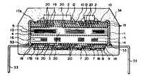
제 3a 도 및 제 3b 도는 본 발명에 따른 다층혼성집적회로의 제 3 실시예를 나타낸 것으로, 제 3a 도는 사시도이고, 제 3b 도는 제 3a 도의 단면도이다.3A and 3B show a third embodiment of a multi-layer hybrid integrated circuit according to the present invention. FIG. 3A is a perspective view and FIG. 3B is a sectional view of FIG. 3A.
도면에서 참조부호 1은 제 1 도에서의 1C 및 제 2 도에서의 1D와 동일한 적층체를 나타내는 바, 이 적층체(1)는 캐패시터(5) 또는 인덕터(16)를 포함함과 더불어 저항 또는 내부배선부도 포함하게 된다. 한편, 캐패시터(5)는 유전체(3)와 금속막(4)을 적층함으로써 형성되는 것으로, 각 캐패시터(5)의 전극은 적층체(1)의 측면에 형성된 단자(11)에 접속되게 된다. 그리고, 인덕터(16)은 페라이트(15)와 도체막(19)을 후막인쇄공정에 의해 적층해서 도체막(19)이 코일모양을 하도록 형성한 것이다. 한편, 적층체내에서 인덕터를 구성하는 도체층(19)과 페라이트(15)를 조합해서 트랜스를 구성하는 경우도 있다.In the drawings,
저항회로망(9)은 적층체(1)의 한쪽면에 형성되는 바, 이 저항회로망(9)은 저항층(8)과 적층체(1)의 한쪽면에 형성된 유리층(6)상에 형성되는 도체층(8B)으로 이루어지는데, 여기서는 저항회로망(9)을 보호하기 위해 유리층(6B)으로 덮도록 되어 있다. 제 3b 도에는 저항회로망(9)이 적층체(1)의 한쪽면에만 형성되는 경우를 나타냈지만, 이와 같은 저항회로망(9)은 적층체(1)의 양쪽면에 형성될 수도 있다. 도면에서 참조부호 50은 IC의 본딩을 위해 적층체(1)의 표면상에 형성되는 패드이다.The
상기 적층체(1)와 저항회로망(9), 패드(50) 및 단자(11)는 예컨대 800℃전후에서 소결되게 된다.The
참조부호 51은 소결된 적층체(1)의 표면에 형성된 금속막을 나타내고, 31은 이 금속막(51)상에 고착되는 베어칩(bare chip)을 나타내는 바, 이 베어칩(31)은 예컨대 반도체베어칩 또는 집적회로베어칩 등이다. 상기 금속막(51)은 금속(은, 동, 알루미늄, 몰리브덴, 금 또는 팔라듐)의 후막인쇄, 증착, 스퍼터링등에 의해 형성되게 된다.Reference numeral 51 denotes a metal film formed on the surface of the
상기 베어칩(31)을 금속막(51)막에 고착시키는 방법의 일례로서, 도전페이스트(conductive paste)를 후막인쇄공정에 의해 적층체(1)사에 도포하고, 그 위에 베어칩(31)을 올려 놓은 상태에서 150~160℃정도로 가열함으로써 금속막(51)을 그 위에 베어칩(31)이 고착된 상태로 형성되게 된다. 그리고, 참조부호 32는 베어칩(31)과 패드(50)를 본딩하는 금으로 된 금속선이다. 한편, 본 실시예에 있어서는 베어칩(31)을 적층체(1)의 한쪽면에만 형성시킨 경우에 대해 설명했지만, 양쪽면에 형성시킬 수도 있다.As an example of a method of fixing the
이와 같이 베어칩(31)을 적층체(1)상에 탑재시킨 후에, 적층체(1)의 단자(11)를 L자형으로 오프셋인쇄된 리드프레임(lead frame)이 리드단자(33; 도체핀)중 대응되는 리드단자위에 올려 놓고, 도전페이스트 또는 납땜(53) 등으로 접속시키게 된다. 그후, 수지(34)에 의해 적층체(1)와 베어칩(31), 본딩와이어(32; 금속선) 및 리드단자(33)의 일부가 덮히도록 몰드한다. 결과적으로, 리드프레임의 바깥부분(도시생략)이 없어지게 된다.After mounting the
제 4 도는 본 발명에 따른 다층혼성집적회로의 제 4 실시예를 나타낸 것으로, 제 2b 도의 적층체(1D)상에는 다수의 전자부품(2; 베어칩)이 탑재되어 있는 바, 적층체(1D)와 전자부품(2)을 포함하는 전체가 수지(34)에 의해 몰드되고, 적층체(1D)의 단자(11)는 리드프레임의 리드단자(33)와 접속되어 있다.4 shows a fourth embodiment of a multi-layer hybrid integrated circuit according to the present invention, in which a plurality of electronic components 2 (bare chips) are mounted on the laminate 1D of FIG. And the whole including the
제 3 도 및 제 4 도에 도시된 실시예에 있어서는 전자부품과, 캐패시터, 인덕터 및 저항을 포함하는 내부소자가 적층체의 측면에 설치된 단자(11)또는 내부배선부를 매개로 접속되게 된다.In the embodiments shown in FIGS. 3 and 4, an electronic component, an internal element including a capacitor, an inductor, and a resistor are connected via a terminal 11 or an internal wiring provided on the side of the stack.
제 5a 도 및 제 5b 도는 본 발명에 따른 다층혼성집적회로의 제 3 실시예에 의해 실현되는 회로의 예를 나타낸 회로도로서, 능동소자로서의 베어칩(31) 이외에 2점쇄선(1E)으로 둘러쌓인 부분, 즉 캐패시터(55)와 인덕터(56) 및 저항(57)을 포함하는 수동소자도 단일칩내에 내장되게 된다. 여기서, 참조부호 33은 혼성 집적회로의 외부접속을 위한 리드단자를 나타낸다.5A and 5B are circuit diagrams showing an example of a circuit realized by the third embodiment of the multi-layer hybrid integrated circuit according to the present invention, which is surrounded by two-dot chain lines 1E in addition to the
본 실시예에 있어서는 베어칩(31)이 직접 또는 금속막(51)을 매개로 적층체(1)상에 고착되게 되는데, 이때 금속막(51)은 히트싱크(heat sink)로서 작용하게 된다. 그리고, 산화티타늄의 열전도율 및 티탄산바륨의 열전도율은 각각 0.0067w/cm·℃ 및 0.0028w/cm·℃이지만 은의 열전도율 및 동의 열전도율은 각가 4.10w/cm·℃ 및 3.80w/cm·℃로 비교적 높은 값이기 때문에, 은 또는 동을 금속막(51)으로서 사용할 경우에는 베어칩(31)에 발생하는 열이 분사되어 베어칩(31)의 열폭주를 방지할 수 있게 된다.In the present embodiment, the
상술한 바와 같이 제 5a 도 및 제 5b 도에 도시된 회로는 능동소자인 반도체베어칩과 수동소자인 적층체가 단일의 혼성 집적회로칩내에 내장되어 수지에 의해 몰드되게 되므로, 반도체칩이 탑재되는 인쇄회로 기판상에 수동소자를 설치할 필요가 없게 되어 혼성집적회로의 부품수가 대폭적으로 줄어 들게 된다. 또, 인쇄회로기판상에 능동소자와 수동소자를 접속시키기 위한 인쇄패턴을 형성할 필요가 없게 되어 인쇄패턴의 구조가 간략화되게 된다.As described above, in the circuits shown in FIGS. 5A and 5B, the semiconductor bare chip as an active element and the passive layer as a stack are embedded in a single hybrid integrated circuit chip to be molded by resin, thereby printing the semiconductor chip. There is no need to install passive elements on the circuit board, which greatly reduces the number of components in the hybrid integrated circuit. In addition, it is not necessary to form a printed pattern for connecting the active element and the passive element on the printed circuit board, thereby simplifying the structure of the printed pattern.
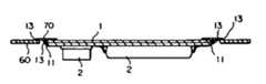
제 6a 도 및 제 6b 도는 본 발명에 따른 다층혼성집적회로의 제 5 실시예를 나타낸 도면으로, 제 6a 도는 평면도를 나타내고, 제 6b 도는 단면도를 나타낸다. 그리고, 제 6c 도는 제 6a 도에 도시된 다층혼성집적회로가 마더기판(mother board)에 장착된 구조를 나타내는 측면단면도이고, 제 6d 도는 제 6c 도의 일부 확대단면도이다. 상기 제 6a 도 내지 제 6d 도에 도시된 제 5 실시예의 특징은 마더기판(60)과 적층체(1)사이에 중계기판(70)을 사용한다는 것인 바, 이 중계기판(70)은 탄력이 좋은 플라스틱판 및 그 기판(70)상에 인쇄되는 도체패턴(73)으로 이루어진다.6A and 6B show a fifth embodiment of a multi-layer hybrid integrated circuit according to the present invention. FIG. 6A shows a plan view and FIG. 6B shows a sectional view. 6C is a side cross-sectional view showing a structure in which the multilayer hybrid integrated circuit shown in FIG. 6A is mounted on a mother board, and FIG. 6D is a partially enlarged cross-sectional view of FIG. 6C. A characteristic of the fifth embodiment shown in FIGS. 6A to 6D is that the
상기 중계기판(70)은 적층체(1)에 꼭맞는 구멍 또는 창을 갖추고 있으므로, 중계기판(70)은 링형상으로 이루어지게 된다.Since the
상기 중계기판(70)상의 도체패턴(73)을 적층체(1)상에 형성된 도체패턴(74) 또는 적층체(1)의 단자(11)중 대응되는 것에 납땜(13)으로 접속시켜 적층체(1)와 중계기판(70)을 접속시키게 된다. 한편, 중계기판(70)의 창은 적층체(1)의 면적보다 작으므로 적층체(1)가 링형상의 중계기판(70)상에 위치하게 된다.The
한편, 마더기판(60)에는 중계기판(70)의 면적보다 큰 창(76)이 설치되어 있는 바, 그 창(76)에 적층체(1)를 양자간에 작은 간격(예컨대 0.2mm정도)을 두고 끼워 넣은 다음, 중계기판(70)의 도체패턴(73)을 마더기판(60)상의 대응되는 도체패턴(77)에 납땜(13)으로 접속시킨다. 그리고, 상기 납땜(13)으로 접속시키는 동안 접착제(80)를 사용해서 적층체(1)을 중계기관(70)에 고정시키게 된다.On the other hand, the
이와같이, 적층체(1)가 탄력이 좋은 중계기판(70)을 매개로 마더기판(60)에 접속되는 경우에는, 마더기판(60)에 어떤 충격이 가해지더라도 탄력이 좋은 중계기판(70)에 의해 그 충력이 완화되어 적층체(1)에는 충격이 가해지지 않게 되고, 더욱이 납땜에 과도한 충격이 가해지지 않게 되므로 납땜에 의한 접속이 떨어지지 않게 된다.In this way, when the
또, 마더기판(60)에는 창(76)이 설치되어 있기 때문에 마더기판(60)의 표면으로부터 전자부품(2)의 정상까지의 높이(h2)는 창(76)이 설치되지 않은 경우의 높이보다 낮아지게 된다. 물론, 부품의 높이가 그다지 문제로 되지 않는다면 마더기판(60)에 창(76)을 설치하지 않을 수도 있다.Moreover, since the
제 7a 도 및 제 7b 도는 제 6a 도 내지 제 6d 도에 도시된 본 발명에 따른 다층혼성집적회로의 제 5 실시예를 변형한 제 6 실시예를 나타낸 것으로, 그 특징은 적층체(1)를 마더기판(60)에 거꾸로 접속시키는데 있다.7A and 7B show a sixth embodiment which is a modification of the fifth embodiment of the multilayer hybrid integrated circuit according to the present invention shown in FIGS. 6A to 6D. The
제 6 도 및 제 7 도에 도시된 실시예에 있어서는 적층체로서 내부배선부를 갖춘 적층체, 내부배선부를 갖추지 않은 적층체 또는 제 3 도에 도시된 바와 같이 반도체베어칩이 몰드된 적층체를 사용해도 된다. 더욱이, 제 6 도 및 제 7 도에서는 적층체(1)의 한쪽면에 전자부품(2)를 탑재시키는 경우에 대해서만 나타냈지만, 제 6 도 또는 제 7 도에서의 적층체(1)의 양쪽면에 전자부품(2)을 탑재시킬 수도 있다.In the embodiment shown in Figs. 6 and 7, a laminate having an internal wiring portion, a laminate having no internal wiring portion, or a laminate in which a semiconductor bare chip is molded as shown in Fig. 3 is used. You may also Moreover, although only the case where the
한편, 본 발명은 상기 각 실시예에 한정되지 않고, 발명의 요지를 이탈하지 않는 범위내에서 여러 가지로 변형해서 실시할 수가 있다.In addition, this invention is not limited to each said Example, It can variously deform and implement within the range which does not deviate from the summary of invention.
Claims (10)
Translated fromKoreanApplications Claiming Priority (6)
| Application Number | Priority Date | Filing Date | Title |
|---|---|---|---|
| JP01-007378 | 1989-01-14 | ||
| JP1017378AJP2749854B2 (en) | 1989-01-26 | 1989-01-26 | Dimming control method for remote monitoring and control system |
| JP01-050773 | 1989-03-02 | ||
| JP1050773AJPH02229462A (en) | 1989-03-02 | 1989-03-02 | Structure of laminated hybrid integrated circuit component |
| JP1170842AJPH0335586A (en) | 1989-07-02 | 1989-07-02 | Structure of hybrid integrated circuit component |
| JP01-170842 | 1989-07-02 |
Publications (2)
| Publication Number | Publication Date |
|---|---|
| KR900012357A KR900012357A (en) | 1990-08-03 |
| KR930010076B1true KR930010076B1 (en) | 1993-10-14 |
Family
ID=27281793
Family Applications (1)
| Application Number | Title | Priority Date | Filing Date |
|---|---|---|---|
| KR1019900000397AExpired - Fee RelatedKR930010076B1 (en) | 1989-01-14 | 1990-01-13 | Multilayer Hybrid Integrated Circuit |
Country Status (2)
| Country | Link |
|---|---|
| US (1) | US5428885A (en) |
| KR (1) | KR930010076B1 (en) |
Cited By (1)
| Publication number | Priority date | Publication date | Assignee | Title |
|---|---|---|---|---|
| US7230815B2 (en) | 2004-12-24 | 2007-06-12 | Samsung Electro-Mechanics Co., Ltd | Multilayered chip capacitor and printed circuit board having embedded multilayered chip capacitor |
Families Citing this family (34)
| Publication number | Priority date | Publication date | Assignee | Title |
|---|---|---|---|---|
| JP3461204B2 (en)* | 1993-09-14 | 2003-10-27 | 株式会社東芝 | Multi-chip module |
| US5787569A (en)* | 1996-02-21 | 1998-08-04 | Lucent Technologies Inc. | Encapsulated package for power magnetic devices and method of manufacture therefor |
| DE19632200C2 (en)* | 1996-08-09 | 2002-09-05 | Bosch Gmbh Robert | Multichip module |
| US5841686A (en)* | 1996-11-22 | 1998-11-24 | Ma Laboratories, Inc. | Dual-bank memory module with shared capacitors and R-C elements integrated into the module substrate |
| US7336468B2 (en) | 1997-04-08 | 2008-02-26 | X2Y Attenuators, Llc | Arrangement for energy conditioning |
| US7321485B2 (en) | 1997-04-08 | 2008-01-22 | X2Y Attenuators, Llc | Arrangement for energy conditioning |
| US9054094B2 (en) | 1997-04-08 | 2015-06-09 | X2Y Attenuators, Llc | Energy conditioning circuit arrangement for integrated circuit |
| DE19728692C2 (en)* | 1997-07-04 | 2002-04-11 | Infineon Technologies Ag | IC component with passive components |
| US6351033B1 (en)* | 1999-10-06 | 2002-02-26 | Agere Systems Guardian Corp. | Multifunction lead frame and integrated circuit package incorporating the same |
| JP3679687B2 (en)* | 2000-06-08 | 2005-08-03 | 三洋電機株式会社 | Hybrid integrated circuit device |
| AU2002328074A1 (en)* | 2002-08-30 | 2004-03-19 | Bc Components Holdings B.V. | Electrical component with impedance and resistor |
| EP1610384A3 (en)* | 2004-06-14 | 2008-11-19 | Denso Corporation | Electronic unit with a substrate where an electronic circuit is fabricated |
| JP2008535207A (en) | 2005-03-01 | 2008-08-28 | エックストゥーワイ アテニュエイターズ,エルエルシー | Regulator with coplanar conductor |
| US7613009B2 (en)* | 2006-03-15 | 2009-11-03 | Tdk Corporation | Electrical transition for an RF component |
| JP4850576B2 (en)* | 2006-05-01 | 2012-01-11 | アルプス電気株式会社 | Manufacturing method of circuit module and collective substrate for circuit module used therefor |
| US7742276B2 (en)* | 2007-03-30 | 2010-06-22 | Industrial Technology Research Institute | Wiring structure of laminated capacitors |
| JP2010028017A (en)* | 2008-07-24 | 2010-02-04 | Fuji Electric Device Technology Co Ltd | Thin inductor, manufacturing method thereof, and ultra small size power converter using the thin inductor |
| USD794644S1 (en)* | 2009-01-07 | 2017-08-15 | Samsung Electronics Co., Ltd. | Memory device |
| USD795262S1 (en)* | 2009-01-07 | 2017-08-22 | Samsung Electronics Co., Ltd. | Memory device |
| USD794642S1 (en)* | 2009-01-07 | 2017-08-15 | Samsung Electronics Co., Ltd. | Memory device |
| USD794643S1 (en)* | 2009-01-07 | 2017-08-15 | Samsung Electronics Co., Ltd. | Memory device |
| USD794641S1 (en)* | 2009-01-07 | 2017-08-15 | Samsung Electronics Co., Ltd. | Memory device |
| USD794034S1 (en)* | 2009-01-07 | 2017-08-08 | Samsung Electronics Co., Ltd. | Memory device |
| USD795261S1 (en)* | 2009-01-07 | 2017-08-22 | Samsung Electronics Co., Ltd. | Memory device |
| USD680119S1 (en)* | 2011-11-15 | 2013-04-16 | Connectblue Ab | Module |
| USD689053S1 (en)* | 2011-11-15 | 2013-09-03 | Connectblue Ab | Module |
| USD680545S1 (en)* | 2011-11-15 | 2013-04-23 | Connectblue Ab | Module |
| USD668658S1 (en)* | 2011-11-15 | 2012-10-09 | Connectblue Ab | Module |
| USD668659S1 (en)* | 2011-11-15 | 2012-10-09 | Connectblue Ab | Module |
| USD692896S1 (en)* | 2011-11-15 | 2013-11-05 | Connectblue Ab | Module |
| KR20160000329A (en)* | 2014-06-24 | 2016-01-04 | 삼성전기주식회사 | Multi-layered inductor and board having the same mounted thereon |
| US10083781B2 (en) | 2015-10-30 | 2018-09-25 | Vishay Dale Electronics, Llc | Surface mount resistors and methods of manufacturing same |
| US10438729B2 (en) | 2017-11-10 | 2019-10-08 | Vishay Dale Electronics, Llc | Resistor with upper surface heat dissipation |
| US10993347B2 (en)* | 2018-11-20 | 2021-04-27 | Innolux Corporation | Electronic device and tiled electronic system comprising the same |
Family Cites Families (28)
| Publication number | Priority date | Publication date | Assignee | Title |
|---|---|---|---|---|
| US3346689A (en)* | 1965-01-29 | 1967-10-10 | Philco Ford Corp | Multilayer circuit board suing epoxy cards and silver epoxy connectors |
| US3398232A (en)* | 1965-10-19 | 1968-08-20 | Amp Inc | Circuit board with interconnected signal conductors and interconnected shielding conductors |
| US3484654A (en)* | 1967-03-24 | 1969-12-16 | American Can Co | High-speed printing of electronic components and articles produced thereby |
| US3843951A (en)* | 1973-01-26 | 1974-10-22 | Bell Northern Research Ltd | Connection of an electrical component to a flexible circuit |
| US4342143A (en)* | 1974-02-04 | 1982-08-03 | Jennings Thomas A | Method of making multiple electrical components in integrated microminiature form |
| FR2404990A1 (en)* | 1977-10-03 | 1979-04-27 | Cii Honeywell Bull | SUBSTRATE FOR THE INTERCONNECTION OF ELECTRONIC COMPONENTS WITH INTEGRATED CIRCUITS, EQUIPPED WITH A REPAIR DEVICE |
| DE2915240A1 (en)* | 1978-06-28 | 1980-01-03 | Mitsumi Electric Co | PRINTED CIRCUIT |
| GB2045540B (en)* | 1978-12-28 | 1983-08-03 | Tdk Electronics Co Ltd | Electrical inductive device |
| JPS55130198A (en)* | 1979-03-30 | 1980-10-08 | Hitachi Ltd | Hybrid integrated circuit board for tuner |
| JPS5662345A (en)* | 1979-10-26 | 1981-05-28 | Hitachi Ltd | Load frame and semiconductor device |
| US4501960A (en)* | 1981-06-22 | 1985-02-26 | Motorola, Inc. | Micropackage for identification card |
| JPS5976455A (en)* | 1982-10-26 | 1984-05-01 | Tdk Corp | Hybrid integrated circuit |
| JPS59175753A (en)* | 1983-03-25 | 1984-10-04 | Toshiba Corp | Semiconductor device and lead frame |
| US4535385A (en)* | 1983-04-22 | 1985-08-13 | Cray Research, Inc. | Circuit module with enhanced heat transfer and distribution |
| JPS6084854A (en)* | 1983-10-14 | 1985-05-14 | Toshiba Corp | Resin-encapsulated semiconductor device |
| JPS60136294A (en)* | 1983-12-23 | 1985-07-19 | 株式会社日立製作所 | Ceramic multilayer wiring circuit board |
| US4754371A (en)* | 1984-04-27 | 1988-06-28 | Nec Corporation | Large scale integrated circuit package |
| US4631820A (en)* | 1984-08-23 | 1986-12-30 | Canon Kabushiki Kaisha | Mounting assembly and mounting method for an electronic component |
| JPS6261015A (en)* | 1985-09-11 | 1987-03-17 | Fujikura Ltd | Optical fiber core |
| US4874721A (en)* | 1985-11-11 | 1989-10-17 | Nec Corporation | Method of manufacturing a multichip package with increased adhesive strength |
| US4890194A (en)* | 1985-11-22 | 1989-12-26 | Texas Instruments Incorporated | A chip carrier and mounting structure connected to the chip carrier |
| JPS62216259A (en)* | 1986-03-17 | 1987-09-22 | Fujitsu Ltd | Manufacturing method and structure of hybrid integrated circuit |
| JPH0620025B2 (en)* | 1986-05-28 | 1994-03-16 | ティーディーケイ株式会社 | Multilayer LC filter parts |
| US4803595A (en)* | 1986-11-17 | 1989-02-07 | International Business Machines Corporation | Interposer chip technique for making engineering changes between interconnected semiconductor chips |
| US4922324A (en)* | 1987-01-20 | 1990-05-01 | Kabushiki Kaisha Toshiba | Semiconductor integrated circuit device |
| US4922377A (en)* | 1987-11-16 | 1990-05-01 | Hitachi, Ltd. | Module and a substrate for the module |
| JPH0281648A (en)* | 1988-09-20 | 1990-03-22 | Hitachi Ltd | Thick film thermal recording head |
| JPH02114697A (en)* | 1988-10-25 | 1990-04-26 | Matsushita Electric Ind Co Ltd | Hybrid integrated circuit device |
- 1990
- 1990-01-13KRKR1019900000397Apatent/KR930010076B1/ennot_activeExpired - Fee Related
- 1993
- 1993-01-27USUS08/009,410patent/US5428885A/ennot_activeExpired - Lifetime
Cited By (1)
| Publication number | Priority date | Publication date | Assignee | Title |
|---|---|---|---|---|
| US7230815B2 (en) | 2004-12-24 | 2007-06-12 | Samsung Electro-Mechanics Co., Ltd | Multilayered chip capacitor and printed circuit board having embedded multilayered chip capacitor |
Also Published As
| Publication number | Publication date |
|---|---|
| KR900012357A (en) | 1990-08-03 |
| US5428885A (en) | 1995-07-04 |
Similar Documents
| Publication | Publication Date | Title |
|---|---|---|
| KR930010076B1 (en) | Multilayer Hybrid Integrated Circuit | |
| US8050045B2 (en) | Electronic component and method of manufacturing the same | |
| US6301114B1 (en) | Multilayered electronic part and electronic circuit module including therein the multilayered electronic part | |
| US7649252B2 (en) | Ceramic multilayer substrate | |
| EP0789390B1 (en) | A method for producing a multilayer hybrid circuit | |
| CN1973587A (en) | Hybrid electronic component and method for manufacturing the same | |
| US20050270748A1 (en) | Substrate structure integrated with passive components | |
| JPS6266506A (en) | High electrostatic capacitance bus bar containing multilayerceramic capacitor | |
| US20050134405A1 (en) | Electronic device and semiconductor device | |
| JPH0210598B2 (en) | ||
| JP2019179865A (en) | Circuit board and method for manufacturing circuit board | |
| JPH03156905A (en) | Electronic component using stacked capacitor | |
| US4568999A (en) | Multilayer ceramic capacitor on printed circuit | |
| JP3246166B2 (en) | Thin film capacitors | |
| JP2571389B2 (en) | Stacked hybrid integrated circuit components | |
| JPH02164096A (en) | Multilayer electronic circuit board and its manufacture | |
| JP4458033B2 (en) | Multilayer electronic circuit structure and manufacturing method thereof | |
| JPH01102990A (en) | Small electronic parts mounting circuit | |
| JPH05226506A (en) | Surface mounted composite part and manufacturing method thereof | |
| JP4292860B2 (en) | Multilayer electronic circuit device and manufacturing method thereof | |
| JP2003078103A (en) | Circuit board | |
| JP2572626Y2 (en) | Multilayer circuit board | |
| JP3250166B2 (en) | Multilayer composite electronic components | |
| JP2002100697A (en) | Electronic component and electronic device provided with the same | |
| JPH03136396A (en) | Electronic circuit component, manufacture thereof and electronic circuit apparatus |
Legal Events
| Date | Code | Title | Description |
|---|---|---|---|
| PA0109 | Patent application | St.27 status event code:A-0-1-A10-A12-nap-PA0109 | |
| R17-X000 | Change to representative recorded | St.27 status event code:A-3-3-R10-R17-oth-X000 | |
| PG1501 | Laying open of application | St.27 status event code:A-1-1-Q10-Q12-nap-PG1501 | |
| A201 | Request for examination | ||
| P11-X000 | Amendment of application requested | St.27 status event code:A-2-2-P10-P11-nap-X000 | |
| P13-X000 | Application amended | St.27 status event code:A-2-2-P10-P13-nap-X000 | |
| PA0201 | Request for examination | St.27 status event code:A-1-2-D10-D11-exm-PA0201 | |
| G160 | Decision to publish patent application | ||
| PG1605 | Publication of application before grant of patent | St.27 status event code:A-2-2-Q10-Q13-nap-PG1605 | |
| E701 | Decision to grant or registration of patent right | ||
| PE0701 | Decision of registration | St.27 status event code:A-1-2-D10-D22-exm-PE0701 | |
| GRNT | Written decision to grant | ||
| PR0701 | Registration of establishment | St.27 status event code:A-2-4-F10-F11-exm-PR0701 | |
| PR1002 | Payment of registration fee | St.27 status event code:A-2-2-U10-U11-oth-PR1002 Fee payment year number:1 | |
| PR1001 | Payment of annual fee | St.27 status event code:A-4-4-U10-U11-oth-PR1001 Fee payment year number:4 | |
| PR1001 | Payment of annual fee | St.27 status event code:A-4-4-U10-U11-oth-PR1001 Fee payment year number:5 | |
| PR1001 | Payment of annual fee | St.27 status event code:A-4-4-U10-U11-oth-PR1001 Fee payment year number:6 | |
| PR1001 | Payment of annual fee | St.27 status event code:A-4-4-U10-U11-oth-PR1001 Fee payment year number:7 | |
| PR1001 | Payment of annual fee | St.27 status event code:A-4-4-U10-U11-oth-PR1001 Fee payment year number:8 | |
| PR1001 | Payment of annual fee | St.27 status event code:A-4-4-U10-U11-oth-PR1001 Fee payment year number:9 | |
| PR1001 | Payment of annual fee | St.27 status event code:A-4-4-U10-U11-oth-PR1001 Fee payment year number:10 | |
| PR1001 | Payment of annual fee | St.27 status event code:A-4-4-U10-U11-oth-PR1001 Fee payment year number:11 | |
| FPAY | Annual fee payment | Payment date:20041012 Year of fee payment:12 | |
| PR1001 | Payment of annual fee | St.27 status event code:A-4-4-U10-U11-oth-PR1001 Fee payment year number:12 | |
| LAPS | Lapse due to unpaid annual fee | ||
| PC1903 | Unpaid annual fee | St.27 status event code:A-4-4-U10-U13-oth-PC1903 Not in force date:20051015 Payment event data comment text:Termination Category : DEFAULT_OF_REGISTRATION_FEE | |
| PC1903 | Unpaid annual fee | St.27 status event code:N-4-6-H10-H13-oth-PC1903 Ip right cessation event data comment text:Termination Category : DEFAULT_OF_REGISTRATION_FEE Not in force date:20051015 | |
| R18-X000 | Changes to party contact information recorded | St.27 status event code:A-5-5-R10-R18-oth-X000 | |
| P22-X000 | Classification modified | St.27 status event code:A-4-4-P10-P22-nap-X000 | |
| R18-X000 | Changes to party contact information recorded | St.27 status event code:A-5-5-R10-R18-oth-X000 | |
| P22-X000 | Classification modified | St.27 status event code:A-4-4-P10-P22-nap-X000 |