KR930003168B1 - Input device of tablet type - Google Patents
Input device of tablet typeDownload PDFInfo
- Publication number
- KR930003168B1 KR930003168B1KR1019850005072AKR850005072AKR930003168B1KR 930003168 B1KR930003168 B1KR 930003168B1KR 1019850005072 AKR1019850005072 AKR 1019850005072AKR 850005072 AKR850005072 AKR 850005072AKR 930003168 B1KR930003168 B1KR 930003168B1
- Authority
- KR
- South Korea
- Prior art keywords
- wave
- input
- medium
- acoustic wave
- detection
- Prior art date
- Legal status (The legal status is an assumption and is not a legal conclusion. Google has not performed a legal analysis and makes no representation as to the accuracy of the status listed.)
- Expired - Fee Related
Links
Images


Classifications
- G—PHYSICS
- G06—COMPUTING OR CALCULATING; COUNTING
- G06F—ELECTRIC DIGITAL DATA PROCESSING
- G06F3/00—Input arrangements for transferring data to be processed into a form capable of being handled by the computer; Output arrangements for transferring data from processing unit to output unit, e.g. interface arrangements
- G06F3/01—Input arrangements or combined input and output arrangements for interaction between user and computer
- G06F3/03—Arrangements for converting the position or the displacement of a member into a coded form
- G06F3/041—Digitisers, e.g. for touch screens or touch pads, characterised by the transducing means
Landscapes
- Engineering & Computer Science (AREA)
- General Engineering & Computer Science (AREA)
- Theoretical Computer Science (AREA)
- Human Computer Interaction (AREA)
- Physics & Mathematics (AREA)
- General Physics & Mathematics (AREA)
- Position Input By Displaying (AREA)
- Length Measuring Devices Characterised By Use Of Acoustic Means (AREA)
Abstract
Translated fromKoreanDescription
Translated fromKorean제1도는 본원 발명의 일실시예도.1 is an embodiment of the present invention.
제2도는 그 부분 확대도.2 is an enlarged view of a part thereof.
제3도, 제4도는 탄성파전파의 원리를 설명한 모식도.3 and 4 are schematic diagrams explaining the principle of the acoustic wave propagation.
제5도, 제6도는 탄성파의 검출방법의 설명도.5 and 6 are explanatory diagrams of a method for detecting an acoustic wave.
제7(a)도,제7(b)도는 계수회로의 설명도.7 (a) and 7 (b) are explanatory diagrams of a counting circuit.
제8도는 입력펜의 좌표를 구하는 방법의 설명도.8 is an explanatory diagram of a method of obtaining coordinates of an input pen.
제9도는 지연시간의 설명도.9 is an explanatory diagram of a delay time.
제10도는 제1도의 계수회로의 일실시예의 설명도.10 is an explanatory diagram of one embodiment of the counting circuit of FIG.
제11도는 제10도의 동작의 설명도.11 is an explanatory diagram of the operation of FIG.
제12도, 제13도는 표 1 의 일실시예를 나타낸 데이터도.12 and 13 are data diagrams showing one embodiment of Table 1;
제14도는 감도분포의 모식도.14 is a schematic diagram of the sensitivity distribution.
제15도, 제16도는 감도분포의 측정결과도.15 and 16 show measurement results of sensitivity distribution.
제17도는 파형변화를 설명하는 약도.17 is a schematic for explaining a waveform change.
제18도, 제19도는 다른 일실시예를 각각 나타낸 도면.18 and 19 each show another embodiment.
제20도는 입력펜의 경사각과 검출소자에 검출되는 파형의 관계도.20 is a relationship diagram between the inclination angle of the input pen and the waveform detected by the detection element.
제21도는 입력펜으로부터 기입판내로 입사되는 초음파동작의 시뮬레이션 결과도.21 is a simulation result diagram of the ultrasonic motion incident from the input pen into the writing plate.
제22도는 본원 발명에 의한 복합화 기입장치를 나타낸 일실시예도.22 is a diagram showing an embodiment of a composite writing apparatus according to the present invention.
제23도는 복합화에 의한 효과를 나타낸 시뮬레이션 결과도.23 is a simulation result diagram showing the effect of the complexation.
제24도는 본원 발명에 의한 복합화 기입장치의 다른 실시예도.24 is another embodiment of the composite writing apparatus according to the present invention.
제25도는 입력펜측에 개량을 가한 본원 발명에 의한 다른 실시예도.25 is a view showing another embodiment according to the present invention in which the input pen is improved.
제26도는 제25도의 부분 확대도.FIG. 26 is a partial enlarged view of FIG. 25. FIG.
본원 발명은 타블렛형 좌표입력장치에 관한 것이며, 특히 탄성파를 사용하여 입력의 위치좌표를 검출하는 방식의 장치에 관한 것이다.The present invention relates to a tablet-type coordinate input device, and more particularly to a device of the method of detecting the position coordinate of the input using the acoustic wave.
종래, 이 종류의 좌표입력장치로서, (i) 공중전파방식, (ii) 표면 탄성파방식 및 (iii) 판파(板波)방식 등이 제한되어 있다. 이들은 각각 문헌(IEEE TRANSACTIONS ON COMPUTERS, 1970년, 6월, 546∼548페이지, IEEE TRANSACTIONS ON ELECTRONIC COMPUTERS, 1964년 10월, 609∼611페이지, 및 IEEE 1981 ULTRASONIC SYMPOSIUM, 167∼170페이지)에 개시되어 있다.Conventionally, as this kind of coordinate input device, (i) air propagation method, (ii) surface acoustic wave method, and (iii) plate wave method are limited. These are disclosed in IEEE TRANSACTIONS ON COMPUTERS, 1970, June, pages 546-548, IEEE TRANSACTIONS ON ELECTRONIC COMPUTERS, October 1964, pages 609-611, and IEEE 1981 ULTRASONIC SYMPOSIUM, pages 167-170, respectively. have.
(i)의 방식은 온도 등의 주위환경의 영향을 크게 받으므로, 그 보정이 필요하게 된다. 또, 손 등의 장애물의 영향을 직접 받으므로, 통상의 수서(手書)동작과 동등한 형태로 사용할 수 없어서 이용자에게 위화감을 준다. (ii)의 방식도 타블렛에 손을 대면 입력펜의 위치를 정확하게 표정(標定)할 수 없어서 이용자에게 위화감을 준다. 이 방식은 손가락 터치에 의한 메뉴선택입력장치에 적합하지만, 수서문자, 도형을 입력하는 타블렉에의 응용에는 난점이 있다. (iii)의 방식에는 상기 두방식이 갖는 결점이 없어서 통상의 수서동작이 가능하다. 이 방식을 응용하여 액정표시장치나 EL표시장치를 일체화한 투명한 타블렛의 예가 각각 일본국 특개소 56-101278 및 특개소 58-14247에 개시되어 있다. 그러나, 이 방식은 효율적이고 안정된 송수신에 난점이 있다. 이것은 판파가 종파탄성파(縱波彈性波) 비해 약간 전파속도가 느리므로 최초에 전파하는 종파탄성파의 영향을 면할 수 없으며, 전파거리의 증가와 동시에 위상이 변화하기 때문이다. 일본국 특개소 56-101278에서는 아크릴판을 사용한 예가 개시되어 있다. 아크릴판은 저음속(低音速)재료이므로, 분해능을 크게 할 수 있는 이점이 있는 반면, 감쇠상수가 크므로 판파의 전파시간을 정밀도 높게 검출하는 방법이 복잡해져서, 타블렛의 크기도 스스로 제약을 받는다.Since the method of (i) is greatly influenced by the surrounding environment such as temperature, the correction is necessary. In addition, since it is directly affected by an obstacle such as a hand, it cannot be used in a form equivalent to a normal handwriting, which gives the user a sense of discomfort. In the method of (ii), when the user touches the tablet, the position of the input pen cannot be accurately determined, which gives the user a sense of discomfort. This method is suitable for a menu selection input device by finger touch, but has a difficulty in application to a tablet for inputting arithmetic characters and figures. The method of (iii) does not have the drawbacks of the two methods, and thus can perform normal aquatic operation. Examples of transparent tablets in which a liquid crystal display device or an EL display device are integrated by applying this method are disclosed in Japanese Patent Laid-Open Nos. 56-101278 and 58-14247, respectively. However, this method suffers from an efficient and stable transmission and reception. This is because the plate wave has a slightly slower propagation speed than the longitudinal wave, so the influence of the longitudinal wave that propagates at first is inevitable, and the phase changes with the increase of the propagation distance. In Japanese Patent Laid-Open No. 56-101278, an example using an acrylic plate is disclosed. The acrylic plate is a low-sonic material, which has the advantage of increasing the resolution, while the large attenuation constant complicates the method of accurately detecting the propagation time of the plate wave, which limits the tablet size. .
본원 발명의 목적은 입력매체상의 임의의 위치에서 입력위치를 고정밀도, 고분해능으로 검출할 수 있는 타블렛형 좌표입력장치를 제공하는데 있다.SUMMARY OF THE INVENTION An object of the present invention is to provide a tablet type coordinate input device capable of detecting the input position at high accuracy and high resolution at any position on the input medium.
본원 발명의 다른 목적은 입력매체상에 손을 대어도 그 영향을 받지 않고 통상의 수서동작으로 입력조작이 가능한 타블렛형 좌표입력장치를 제공하는데 있다.Another object of the present invention is to provide a tablet-type coordinate input device that is capable of input operation by a normal aquatic operation without being affected by touching the input medium.
본원 발명의 또 다른 목적은 단순한 구성으로 입력일체화 디스플레이장치를 용이하게 구현할 수 있는 타블렛형 좌표입력장치를 제공하는데 있다.Still another object of the present invention is to provide a tablet type coordinate input device that can easily implement an integrated input device with a simple configuration.
본원 발명의 특징은 입력의 위치좌표를 탄성파중 종파탄성파의 전파를 이용하여 검출하는데 있다.It is a feature of the present invention to detect the positional coordinates of an input using the propagation of longitudinal wave acoustic waves in an acoustic wave.
본원 발명의 바람직한 일실시예에 의하면, 탄성파를 전파시키는 매체수단과, 이 매체수단의 최소한 일부에 배설된 탄성파검출수단과, 상기 매체수단의 표면의 임의의 위치에 탄성파를 방사하는 탄성파입력수단과, 상기 방사된 탄성파중 상기 검출수단에 있어서 종파탄성파로서 검출된 탄성파 대응전기신호를 상기 입력수단의 입력위치의 좌표위치정보로서 취출하는 수단으로 이루어지는 것을 특징으로 하는 탄성파를 사용한 타블렛형 좌표입력장치를 제공한다.According to a preferred embodiment of the present invention, there is provided a medium means for propagating an elastic wave, an elastic wave detection means disposed in at least a portion of the medium means, an elastic wave input means for radiating an elastic wave at an arbitrary position on the surface of the medium means; And means for taking out the acoustic wave-corresponding electric signal detected as the longitudinal wave acoustic wave in the detecting means among the radiated elastic waves as coordinate position information of the input position of the input means. to provide.
또한, 상기 검출부는 상기 평판형 매체부의 코너부 측면에 배설되고, 상기 탄성파 입력부재의 선단부와 상기 평판형 매체부는 음향 임피던수가 대략 같은 부재로 구성된다.The detector is arranged on the side of the corner of the flat media portion, and the front end portion of the elastic wave input member and the flat media portion are constituted by members having substantially the same acoustic impedance.
상기 입력수단의 압착위치의 표정화 정보로서 취출하는 수단은 상기 신호를 증폭하는 증폭부와, 이 증폭부에 의해 증폭된 신호와 일정한계 전압과의 비교에 의해 상기 종파탄성파의 전파시간에 대응한 지연펄스신호를 발하는 비교회로와, 상기 입력부재의 압착에 의해 상기 종파탄성파가 상기 평판형 매체부에 방사되고 나서 상기 지연펄스신호가 발해지기까지의 시간을 계수하는 계수회로와, 이 계수회로로부터 전송되는 시간신호를 사용하여 좌표를 산출하는 연산회로로 구성된다.The means for taking out as the facial expression information of the crimp position of the input means includes an amplifying part for amplifying the signal, and corresponding to the propagation time of the longitudinal wave acoustic wave by comparing the signal amplified by the amplifying part with a constant voltage. A comparison circuit for emitting a delay pulse signal, a counting circuit for counting the time from when the longitudinal wave acoustic wave is radiated to the plate-shaped medium by the pressing of the input member, and then the delay pulse signal is emitted; Comprising a calculation circuit for calculating the coordinates using the transmitted time signal.
상기 탄성파입력부재는 축대칭의 도파봉으로 이루어지고, 이 도파봉의 일단부는 선단이 뾰족한 형상을 이루는 동시에 상기 평판형 매체부의 표면의 임의의 위치에 압착될 수 있고, 상기 도파봉의 타단부는 이 도파봉의 대칭축에 직교하는 평면형상을 가지고, 이 평면부와, 상기 평판형 매체부의 단부 또는 표면의 일부에 배설한 상기 검출부에 각각 수신용 압전소자를 부착한다.The elastic wave input member is composed of an axisymmetric waveguide rod, one end of the waveguide having a pointed shape and a crimp at any position on the surface of the flat media portion, the other end of the waveguide A receiving piezoelectric element is attached to each of the planar portions perpendicular to the axis of symmetry of the rod and the detection portion disposed on the flat portion and the end portion or part of the surface of the flat media portion.
본원 발명에 의하면 입력매체수단내를 전파하는 종파를 이용하므로, 이 입력배체수단상에 손을 대어도, 그 영향을 받지 않으며, 통상의 수서동작으로 입력수단을 조작할 수 있다.According to the present invention, the longitudinal wave propagating in the input medium means is used, so that even if a hand is touched on the input medium means, the input means can be operated by a normal arithmetic operation.
또한, 탄성파의 입사효율과 송수신효율을 향상시킬 수 있으므로, 종파탄성파를 정밀도 높게 검출할 수 있는 동시에, 입력매체수단에 오입력(誤入力)이 생기는 특정영역이 없으므로, 입력매체수단상의 임의의 위치에서 입력수단의 입력위치를 고정밀도, 고분해능으로 검출할 수 있다.In addition, since the incidence efficiency and transmission / reception efficiency of the acoustic wave can be improved, the longitudinal wave acoustic wave can be detected with high accuracy, and since there is no specific region where incorrect input occurs in the input medium means, the arbitrary position on the input medium means The input position of the input means can be detected with high precision and high resolution.
더욱이, 입력매체수단을 투명부재로 할 수 있으므로, 입력일체화 디스플레이장치를 용이하게 구현화할 수 있다.Furthermore, since the input medium means can be made of a transparent member, the input integrated display device can be easily implemented.
본원 발명에 의하면, 초음파응용 타블렛에 있어서 펜의 경사에 의해 생기는 매체수단의 파형변화를 저감할 수 있고, 특히 위상의 역전을 방지할 수 있으므로, 고정밀도의 타블렛이 가능하게 된다. 또한, 파형변화를 특별한 검출기나 부가회로를 사용하여 보정하는 타블렛에 비해 간단히 구성할 수 있는 효과가 얻어진다.According to the present invention, since the waveform change of the media means caused by the inclination of the pen in the ultrasonic application tablet can be reduced, and in particular, the reversal of phase can be prevented, a tablet with high accuracy becomes possible. In addition, an effect that can be easily configured is obtained as compared to a tablet which corrects the waveform change using a special detector or an additional circuit.
상기 이외의 본원 발명의 목적, 특징 및 효과는 도면을 참조한 다음의 설명으로 더욱 명백해질 것이다.Objects, features and effects of the present invention other than the above will become more apparent from the following description with reference to the drawings.
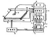
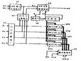
제 1 도는 본원 발명의 일실시예도이다. 매체수단(1)은 유리와 같은 투명한 평판으로 이루어진다. 이 매체수단(1)의 배면에는 표시부(9)가 배치된다. 입력수단(3)은 예를들어 내부에 종파(縱波)탄성파 발생기능을 갖는 표시펜으로 구성되며, 그 선단은 뾰족한 형상을 이루고, 이 선단부로부터 후술하는 바와 같이 종파탄성파가 방사된다. 선단을 첨두화(尖頭化)함으로써, 탄성파방사에너지 밀도가 매우 커지며, 탄성파의 방사효율이 좋아진다. 투명평판(1)의 주변 단부에는 종파검출수단으로서 압전소자(壓電素子)(2a), (2b), (2c), (2d)가 배치된다. 이 종파검출부(2a)~(2d)는 투명평판(1)을 통해 전파되는 종파턴성파를 검출하여 전기신호로서 출력한다.1 is an embodiment of the present invention. The medium means 1 consists of a transparent flat plate such as glass. The display part 9 is arrange | positioned at the back surface of this medium means 1. The input means 3 is constituted, for example, by a display pen having a longitudinal wave acoustic wave generating function therein, the tip of which has a sharp shape, and the longitudinal wave acoustic wave is radiated from the tip as described later. By tipping the tip, the elastic radiation energy density becomes very large and the radiation efficiency of the acoustic wave is improved. At the peripheral end of the transparent flat plate 1,
표시부(9)는 임의의 도형·문자를 표시 가능하게 하는 것으로서, 예를들면 액정표시부로 이루어진다. 표시부(9)에는 표시구동부(8)의 지시하에 표시펜(3)이 투명판(1)상을 묘화했을 때의 패턴이 표시된다. 따라서, 표시펜(3)으로 묘화하면서 그 묘화한 패턴이 표시부(9)에 즉시 표시된다. 묘화로부터 표시까지의 시간은 단시간이며, 작업자에 있어서는 표시펜(3)에 의해 묘화하면서 그 묘화한 패턴의 표시를 관찰할 수 있게 된다.The display unit 9 allows arbitrary graphics and characters to be displayed, for example, a liquid crystal display unit. On the display unit 9, under the direction of the display driver 8, a pattern when the
묘화로부터 표시까지의 처리는 후술하는 바와 같이 선두파검출회로(5), 펄서(4), 시간차계수회로(6), 좌표연산회로(7), 표시구동회로(8)에 의해 행해진다.The processing from the drawing to the display is performed by the head
여기서, 펄서(4)는 주기적으로 펄스를 발생한다. 이 펄스는 표시펜(3) 및 시간차계수회로(6)에 입력된다. 표시펜(3)에서는 종파탄성파의 발생트리거로 되며, 펄스를 받을 때마다 종파탄성파를 방사한다. 시간차계수회로(6)는 펄서(4)로부터의 펄스를 받고나서 반사파가 도달하기까지의 시간을 계수한다.Here, the
선두파검출회로(5)는 증폭회로(5a), 파형정형회로(5b)로 이루어지고, 검출부(2a)~(2d)의 검출반사파의 선두파 즉 종파탄성파의 제 1파를 검출한다.The leading
좌표연산회로(7)는 시간차계수회로(6)의 검출시간차를 받아서 표시펜(3)의 위치를 연산한다. 표시구동회로(8)는 이 위치를 표시시키기 위해 표시부(9)를 구동한다. 상기 선두파검출회로(5), 시간차계수회로(6) 및 좌표연산회로(7)는 탄성파의 방사에 의해 검출부에서 검출된 종파탄성파의 선두파 대응 전기신호를 입력수단(3)의 압착위치의 표정화정보로서 취출하는 수단을 구성한다.The coordinate
다음에, 동작에 대해 설명한다.Next, the operation will be described.
펄서(4)는 주기적으로 펄스를 표시펜(3), 시간차계수회로(6)에 보낸다. 표시펜에 보내는 펄스는 종파탄성파를 발생시키는데 필요한 전력을 갖는다. 시간차계수회로(6)에 보내는 펄스에 발생시각의 계수시기(始期)를 지정하는 것이므로, 미소진폭으로 좋다.The
표시펜(3)은 펄서(4)의 펄스여기(勵起)에 의해 종파탄성파를 그 펄를 받을 때마다 발생한다. 표시펜(3)은 작업자에 의해 묘화를 받아서, 그 묘화의 과정에서 펄스를 받을 때마다 종파탄성파를 펜선단부로부터 투명판(1)에 방사한다. 이 펜선단부로부터 방사된 종파탄성파는 투명판(1)을 전파하여 검출부(2a)~(2d)에 도달한다. 펄서(4)로부터의 펄스발생으로부터 탄성파의 방사까지의 시간은 극히 단시간이며, 무시할 수 있다. 따라서, 펄스발생으로부터 각 검출부(2a)~(2d)에 종파탄성파가 도달하기까지의 시간은 각 검출부(2a)~(2d)와 표시펜(3)과의 거리에 비례한다. 1회의 펄스에 의해 발생하는 탄성파에 대해 각 검출부에서 검출에 필요한 탄성파는 선두파 즉 종파탄성파의 제 1파이고, 이 선두파 대응 전기신호는 선두파검출회로(5)에서 검출된다.The
시간차계수회로(6)는 펄스의 송출로부터 검출선두파까지의 시간차를 검출한다. 이 시간차는 각 검출부(2a)~(2d) 대응으로 구해진다. 좌표연산회로(7)는 이 각 검출부(2a)~(2d)에 대한 시간차로 부터 그때의 표시펜(3)의 위치를 산출한다. 산출한 표시펜(3)의 위치를 표시부(9)에 표시하기 위해 표시구동회로(8)를 구동시켜서, 표시부(9)에 표시펜(3)의 지시를 행하여 표시시킨다. 이렇게 하여, 표시펜(3)의 이동에 추종하여 표시가 이루어진다.The time difference coefficient circuit 6 detects the time difference from the pulse output to the detection head wave. This time difference is calculated | required corresponding to each detection part 2a-2d. The coordinate
제 2 도는 표시펜(3)의 구체적인 일실시예를 나타낸다. 표시펜(3)은 원추형상의 선단부(10), 이 선단부에 탄성파를 방사하는 탄성파발생부(3b), 원통형 외프레임(3c)으로 이루어진다. 탄성파발생부(3b)는 선단부(10)의 평탄부(3d)에 접착 고정된다. 탄성파발생부(3b)에는 외부로부터 리드선(3a)이 납땜된다. 이 리드선(3a)을 통해 펄서(4)로부터 펄스가 탄성파발생부(3b)에 인가된다.2 shows a specific embodiment of the
탄성파발생부(3b)는 예를들면 압전소자로 이루어진다. 탄성파발생부(3b)는 펄스의 인가에 의해 탄성파(11)를 선단부(10)로 향해 방사한다. 탄성파(11)는 선단부(10)를 그 원추형의 형상의 뾰족한 첨두부(12)로 향해 전파하고, 이 첨두부(12)를 통해 투명판(1)에 방사한다. 투명판(1)에서는 첨두부(12)를 중심으로 하여 그 주위방향(13),(13)으로 탄성파가 전파된다. 이 전파파는 검출부(2)에서 검출된다.The acoustic wave generator 3b is made of, for example, a piezoelectric element. The elastic wave generator 3b radiates the
고체내를 전파하는 탄성파는 종파, 횡파, 표면파 등 여러가지 모드로 이루어진다. 이 가운데 전파속도가 가장 빠른 것은 종파이고, 이 종파의 제 1파를 선두파로서 검출한다.Acoustic waves propagating in a solid state are composed of various modes such as longitudinal waves, shear waves, and surface waves. Among these, the fastest propagation speed is the longitudinal wave, and the first wave of the longitudinal wave is detected as the leading wave.
제 3도는 리드선(3a)에 인가되는 펄서(4)의 펄스를 제3(a)도, 검출부(2)에서 검출한 검출파를 제3(b)도에 나타낸다. 제 3(b)도로부터 명백한 바와 같이 선두에 오는 종파를 선두파로서 검출하고, 그후에 오는 횡파는 검출대상에서 제외한다.FIG. 3 shows the pulses of the
제 4도는 상기 표시펜(3)에서 투명판(1)(표시판(9)은 도면상 생략했음)에 탄성파가 방사되어 전파해 가는 상황을 설명하는 도면이다. 표시펜(3)에 내장하는 탄성파발생부(3b)는 리드선(3a)을 통해 여기펄스를 받으면 탄성파를 방사한다.4 is a view for explaining a situation in which the elastic wave is radiated and propagated from the
이 탄성파는 두께방향의 진동성분과 경방향의 진동성분을 가지고, 이 2개의 파는 선단부(10)의 내부를 전파해간다. 탄성파는 표시펜(3)의 첨두부(12)의 매체(1)와의 접촉점으로부터 매체(1)내에 들어간다. 이때, 모드변환이 일어나고, 도시한 바와 같이 종파성분과 횡파성분의 양쪽이 혼재한 탄성파로 되어서, 이 탄성파가 매체(1)를 전파해간다.This acoustic wave has a vibration component in the thickness direction and a vibration component in the radial direction, and these two waves propagate inside the
종파성분은 횡파성분의 약 2배의 속도를 가지고 있으며, 검출부(2)에서는 종파성분이 먼저 검출되고, 이것을 위치검출용으로서 이용한다. 종파탄성파를 위치검출용으로서 이용하는 이유의 상세는 다음과 같다.The longitudinal wave component has a speed approximately twice that of the transverse wave component, and the
먼저, 본원 발명자들이 투명판(1)을 전파하는 종파성분의 주파수는 표시펜(3)의 선단부(10)를 전파하는 탄성파발생부(3b)의 경방향 진동성분의 주파수와 대략 일치한다는 사실을 발견한 것에 의거한다.First, the inventors have found that the frequency of the longitudinal wave component propagating through the transparent plate 1 is approximately equal to the frequency of the radial vibration component of the elastic wave generating portion 3b propagating through the
투명판(1)을 전파하는 탄성파는 전술한 바와 같이 종파성분과 횡파성분이 혼재한 복잡한 파형으로 되지만, 최초에 검출부(2)에 도달하는 탄성파에는 횡파성분은 포함되지 않으며, 따라서 매우 단순한 종파성분만을 검출할 수 있다(제3도). 횡파성분이 혼재한 탄성파는 표시펜(3)과 검출부(2)와의 거리를 변화시키면, 파형 특히 진폭이 복잡하게 변화하며, 이 거리에 상당한 전파지연시간의 계수는 곤란하다. 이것에 대해, 상기 종파성분만의 경우는 표시펜과 검출부(2)와의 거리를 변화시켜도, 감쇠의 영향을 제외하고 복잡한 진폭변화는 볼 수 없다. 이 파형을 사용함으로써, 거리에 상당한 전파지연시간의 계수가 충분히 가능하다. 또한, 종파는 투명판(1) 내부를 전파하므로, 투명판(1) 표면에 손을 대어도 거의 영향을 받지 않는다.As described above, the elastic wave propagating through the transparent plate 1 is a complex waveform in which the longitudinal wave component and the shear wave component are mixed, but the shear wave component is not included in the elastic wave reaching the
그리고, 종파성분의 진폭은 횡파성분에 비해 매우 작고, 이것을 정밀도 높게 검출하기 위해서는 표시펜(3)으로부터 투명판(1)에의 탄성파의 입사효율을 크게 하는 것이 바람직하다.The amplitude of the longitudinal wave component is very small compared to the transverse wave component, and in order to detect this with high accuracy, it is preferable to increase the incident efficiency of the elastic wave from the
이 점에 착안하여, 표시펜(3)의 탄성파발생부(3b)의 경방향 공진주파수와 투명판(1)의 측면에 접착하는 검출부(2)의 두께방향 공진주파수 또는 경방향 공진주파수가 일치하도록 검출부(2) 및 탄성파발생부(3b)가 구성된다. 또한, 후술하는 바와 같이 표시펜(3)의 선단부(10)와 투명판(1)과의 음향임피던스의 매칭을 고려하는 것이 바람직하다. 이로써, 전파지연시간의 계수가 충분히 가능한 만큼의 진폭을 갖는 안정된 종파파형이 얻어진다.With this in mind, the radial resonant frequency of the acoustic wave generator 3b of the
검출부(2) 및 탄성파발생부(8b)는 바람직하게는 티탄산지르콘산납으로 이루어지는 압전세라믹스로 구성함으로써, 안정된 종파를 얻을 수 있다. 또한, 선단부(10)로서는 투명판(1)을 소다라임유리로 형성할 경우, 이 유리나 또는 A1을 사용하는 것이 바람직하다.The
제5도 및 제6도는 상기 펄서(4)로부터 스타트펄스 ST와 고전압 펄스가 발해짐으로써, 상기 입력평판(1)을 전파하는 종파탄성파가 상기 압전세라믹스(2a)∼(2d)의 어느 하나에 최초로 도달하기까지의 시간 T의 검출방법을 나타내고 있다. 제5도에 나타낸 바와 같이, 상기 압전세라믹스에 도달하는 종파탄성파의 아날로그출력파형 v은 상기 선두파검출회로(5)를 구성하는 증폭회로(5a)에서 증폭된 후, 파형정형회로(5b)에서 일정 한계치를 기준으로 하여 디지탈출력 D으로 변환되며, 상기 시간차계수회로(6)에 있어서 상기 스타트펄스 ST로부터 상기 디지탈출력 D의 최초의 펄스까지의 시간이 검출된다. 탄성파의 아날로그출력 v은 상기 입력펜(3)의 필압(筆壓) 등에 의해 일정한 한계치에 대해 제6도에 나타낸 것과 같이 변화한다. 이 변화의 가장 극단의 경우에 상당하는 것이 상기 입력펜(3)의 상기 입력평판(1)에 대한 업(비접촉), 다운(접촉)의 순시(瞬時)변화이다.5 and 6, the start pulse ST and the high voltage pulse are emitted from the
제6도에 나타낸 바와 같은 파형변화에 대해서는 시간차계수회로(6)까지의 구성에 의해 보정하는 것이 바람직하다. 본원 발명의 일실시예서는, 그 보정을 이 파형의 피크치까지의 시간에 착안한 방법으로 하고 있다. 즉, 일정한계치에 대해 아날로그파형이 v"∼v∼v'로 변화하는데 수반해서, 디지탈출력 D까지의 시간이 각각 T"∼T∼T'로 변화하지만, 어느 경우에도 상기 아날로그 파형의 피크치까지의 시간은 변하지 않으며, 일정치 T+α로 된다. 여기서, 파형이 상승치에 한계치를 넘는 시간 T1과 하강시에 한계치를 넘는 시간 T2를 계수하고, 그중 값(T1+T2)/2을 사용하여 전파시간을 정의하면 필압 등에 의한 파형변동의 영향을 받지 않는 고정밀도의 시간검출을 할 수 있다. 본원 발명의 일실시예에서는 이것을 제7도에 나타낸 구성에 의해 실현하고 있다. 이 구성에 의하면 상기와 같이 하나의 전파시간을 결정하기 위해 T1, T2로 2회 계수할 필요가 없어진다.It is preferable to correct the waveform change as shown in FIG. 6 by the configuration up to the time difference coefficient circuit 6. In one embodiment of the present invention, the correction is made by focusing on the time to the peak value of the waveform. That is, while the analog waveform changes from v "to v to v 'for a certain threshold value, the time to the digital output D changes to T" to T to T', respectively, but in any case up to the peak value of the analog waveform. The time of does not change, and it becomes constant value T + (alpha). Here, the time when the waveform exceeds the threshold value T1 and the time T2 when the waveform falls, the time T2 is exceeded and the propagation time is defined using the value (T1 + T2 ) / 2, the waveform fluctuation due to the pressure, etc. High-precision time detection is not affected by. In one embodiment of the present invention, this is realized by the configuration shown in FIG. According to this configuration, it is not necessary to count twice with T1 and T2 to determine one propagation time as described above.
즉 , 제7도에 있어서 카운터(72)에서 상기 T1을 계수하고, 이것을 레지스터(73)에 격납한다. 그리고, T1에서 T2까지의 시간을 상기 카운터(72)에 사용한 발진기(71)의 클록을 1/2로 분주(分周)하고, 이것을 게이트회로(75)를 통해 카운터(76)에서 계수하고, 상기 레지스터(73)의 값과의 가산처리를 가산기(77)로 행하여 멀티플렉서(78)에 전송한다. 이러한 구성에 의해, 제7(b)도에 나타낸 것과 같이 상기 디지탈출력 D의 펄스폭의 중앙까지의 시간이 계수된다.That is, in Fig. 7, the counter 72 counts the T1 and stores it in the
(x,y)좌표를 구하는 연산시간의 단축은 다음의 방법에 의해 실현하고 있다.The reduction of the calculation time for obtaining the (x, y) coordinates is realized by the following method.
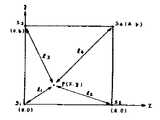
제8도에 있어서, S1∼S4는 압전소자의 위치이며, 점 P(x,y)는 구하는 입력펜의 위치이다.

로 점 P(x,y)의 좌표가 구해진다.The coordinates of the point P (x, y) are obtained.
본 실시예에 의하면, (1)식, (2)식 및 (3)식으로 연산할 경우, 가감산 6회, 곱셈 4회로 되며, 약 218스텝으로 끝나므로, 종래예의 대략 2/3로 스탭수를 저감할 수 있다. 연산의 자릿구가 증가한 경우에는 효과가 더욱 커진다는 것은 이해할 수 있을 것이다.According to the present embodiment, when the calculation is performed by the formulas (1), (2) and (3), the number is 6 additions and 4 multiplications, and ends with about 218 steps. The number can be reduced. It will be appreciated that the effect becomes even greater when the number of places of operations increases.
주위 온도 등의 영향에 의해, 종파탄성파의 전파속도가 변화한 경우, 연산의 빈 시간대를 이용하여 보정계수의 연산이 가능해진다. 본 실시예에서 사용되는 유리판의 경우, 25℃±25℃의 온도변화에 대해 종파탄성파의 전파속도는 ±5% 정도 변화한다. 예를들면, 속도가 증가한 경우에 초기설정치를 적용하면 거리의 측정치가 짧아지고, 표정오차가 생긴다. 이 보상방법으로서 예를들면 제 8도에서 검출점 S1, S2, 파원(波源) P에서 구한 x의 값 x12과 검출점 S1, S2, 파원 P에서 구한 x의 값 x13의 차 |x12-x13|를 모니터해두고, 전파속도가 변화한 경우, |x12-x13|의 값이 허용치 이하로 되었을 때의 속도치를 기억하여 이후의 연산에 사용하면 된다. 전파속도의 변화는 0.2%/℃ 정도이며, 온도변화율은 고작 수분/℃이므로, 수분에 1회의 보정 연산을 실행하면 되며, 좌표위치의 표정에 큰 영향을 주는 일은 없다.When the propagation speed of the longitudinal wave acoustic wave changes due to the ambient temperature or the like, the correction coefficient can be calculated using the free time slot of the calculation. In the case of the glass plate used in the present embodiment, the propagation speed of the longitudinal wave acoustic wave changes by about 5% with respect to a temperature change of 25 ° C ± 25 ° C. For example, when the speed is increased, applying the initial setting value shortens the measurement of distance and causes facial expression error. For example, as the compensation method in the eighth FIG detection point of S1, S2, pawon (波源) value of x x12 and detection points obtained from P S1, S2, a value x13 in x obtained in pawon P The difference | x12 -x13 | is monitored, and when the propagation speed changes, the speed value when the value of | x12 -x13 | becomes less than the allowable value may be used for subsequent calculations. The change in the propagation speed is about 0.2% / ° C, and the rate of change in temperature is only a few minutes / ° C. Therefore, a correction operation is performed once for a few minutes, which does not significantly affect the expression of the coordinate position.
그리고 상기 예에서는 직교좌표를 전제로 하여 설명했지만, 극좌표 등의 다른 좌표계에도 적용할 수 있다. 또한, 3개의 검출점을 잇는 선이 직교하지 않을 경우에 적용할 수 있는 것도 명백하다.In the above example, the explanation is made on the assumption that the rectangular coordinates are used. However, the present invention can be applied to other coordinate systems such as polar coordinates. It is also apparent that the present invention can be applied when a line connecting three detection points is not orthogonal.
또한, 본 실시예에서는 제 4의 검출점 S4을 설정함으로써, 이러한 타블렛의 고정밀도화를 도모할 수 있다. 예를들면, 상기 (1), (2), 및 (3)식에서 구한 (x,y)를 (x1,y1), (1), (4) 및 (5)식에서 구한 (x,y)를 (x1,y2)로 하고, x1과 y1의 차 및 y1및 y2의 차가 허용치 이하로 되지 않을 경우는 좌표치로서 채용하지 않도록 하면, 전파시간의 계수에 오차가 생긴 경우의 좌표오차신호의 출력을 미연에 방지할 수 있다.In addition, in the present embodiment, by setting thefourth detection point S4 , high precision of such a tablet can be achieved. For example, (x, y) obtained from the formulas (1), (2), and (3) above (x, y) obtained from the formulas (x1 , y1 ), (1), (4), and (5) ) to (x1, y2) in the, x, if1 and y, if not to the car, and the car below limit of y1 and y2 of Figure1 when not employed as a coordinate value, an error occurs in the coefficient of time of The output of the coordinate error signal can be prevented in advance.
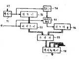
제10도는 제 1도에 나타낸 계수회로(6)의 내부 구성을 나타낸다. 또한, 제11도는 제10도에 나타낸 각종 신호의 타임차트를 나타낸다.FIG. 10 shows the internal structure of the counting circuit 6 shown in FIG. 11 shows time charts of various signals shown in FIG.
제 1도에 있어서, 상기 계수회로(6)에서 계수된 전파시간 T1~T4은 좌표연산회로(7)에 전송되고, 여기서 (x, y)좌표를 계산하여 외부 장치에 출력한다. 제 1 도에 있어서는, 상기 좌표연산회로(예를들면 마이크로콤퓨터(7)에서 출력되는 (x,y)좌표신호가 액정구동회로(8)에 전송되고, 이 액정구동회로(8)에 의해 상기 투명입력평판(1)하에 설치한 액정표시장치(9)를 구동하고 있다. 이것에 의해, 상기 입력펜(3)에 의해 수서된 문자, 도형을 바로 아래의 표시로 확인하면서 입력할 수 있다.In FIG. 1, the propagation times T1 to T4 counted by the counting circuit 6 are transmitted to the coordinate calculating
제10도에 있어서, 상기 계수회로(6)는 스타트펄스발생회로(61), WE신호발생회로(62), 데이터검출회로(63), 발진기(64), 카운터(65), 데이터 셀렉트(66), 레지스터(67a)~(67d), 및 멀티플렉서(68)로 이루어진다.In FIG. 10, the counting circuit 6 includes a start
스타트펄스발생회로(61)에 상기 펄서(4) 및 상기 좌표연산회로(마이크로콤퓨터)(7)에서 각각 스타트신호 ST와 리세트신호 RE가 전송되면, 여기로부터 스타트펄스 ST1가 상기 WE신호발생회로(62) 및 데이터검출회로(63)에 전송된다. 한편, 상기 파형정형회로(5b)의 출력신호 D1~D4는 데이터 셀렉트회로(66)를 통해 데이터검출회로(63)에서 체크되는 동시에, 상기 스타트펄스 ST1에 의해 발진기(64)로부터 발해지는 기본클록펄스 CP의 계수를 개시하고 있는 카운터(65)에 계수종료신호로서 전송된다. 각 데이터신호 D1~D4에 대응하는 기본클록의 카운트수 T1~T4는 각각 레지스터 T1~레지스터 T4에 격납되고, 마이크로콤퓨터(7)에서 전송되는 데이터전환신호 DS1,DS2에 의해 멀티플렉서(68)를 통해 상기 압전소자(2a)~(2d)까지의 전파지연시간에 대응한 데이터로서 입력된다.When the start signal ST and the reset signal RE are transmitted from the
상기 데이터검출회로(63)에서는 데이터신호 D1~D4가 전부 갖추어지지 않으면 상기 WE신호발생회로(62)에서 WE신호가 발하여지지 않도록 되어 있다. WE신호는 제11도에 나타낸 바와같이 ST1가 전송되고나서 시간 t만큼 지연된 곳에서 발생하도록 하고, WE신호가 마이크로콤퓨터(7)에 전송되면 데이터신호T1~T4에서 입력펜의 (x,y)좌표의 연산을 개시한다. 따라서, D1~D4중 하나라도 데이터가 부족하면 나머지 3개의 데이터는 이상(異常)데이터로서 무시되며, 좌표연산에 채용되지 않는다. 이 현상은 입력펜의 업다운시등에 일어나는 경우가 있고, 상기 구성에 의해 그때의 오동작이 방지된다.In the
스타트펄스 ST의 반복주기 τ의 시간내에 상기 마이크로콤퓨터(7)에서의 (x,y)좌표연산이 종료되면, 이주기 τ에 의해 이러한 타블렛형 입력장치에 있어서의 입력속도가 결정된다. 그러므로, 입력속도를 향상시키는데는 상기 좌표 연산시간 tc의 단축화와 제 3 도에서 나타낸 탄성파의 링잉(ringing)의 저감이 필요하다. 전술한 ST1로부터 WE발생까지의 시간 t은 상기 발진기(64)의 클록주파수 fc와 상기 입력평판(1)의 크기 및 종파탄성파의 전파속도 Cp에 의해 한계가 결정된다. 이 클록주파수 fc와 전파속도 Cp의 비로 이러한 타블렛의 분해능이 결정되므로, 이들을 고려할 설정이 필요해진다. 상기 탄성파의 링잉저감에는 상기 입력평판(1)의 주위 측면을 고무재등의 탄성파 흡수부재로 덮는 구성이 바람직하다.When the (x, y) coordinate calculation in the
본 실시예에 있어서 표시펜의 선단을 예리하게 한 것은 위치특정을 정확하게 하기 위해 및 선단으로부터의 방사에너지밀도를 크게 하고, 커플링성을 양호하게 하는 역할을 갖는다.Sharpening the tip of the display pen in this embodiment has a role of increasing the radiation energy density from the tip and improving the coupling property for accurate positioning.
종래의 커플링성을 양호하게 하기 위해, 물 등의 커플링제를 송파부(送波部)와 매체부와의 사이에 개재시키고 있다. 커플링제를 없에고, 음향에너지의 효율적인 전파를 하기 위해, 본 실시예에서는 첨두부(12)와 전파매체(1)와의 음향임피던스를 같거나 그 근방에 설정하여 이루어진다. 이것에 대하여 상세히 설명한다.In order to make the conventional coupling property favorable, a coupling agent, such as water, is interposed between a wave-wave part and a medium part. In order to efficiently propagate the acoustic energy without the coupling agent, in this embodiment, the acoustic impedance between the peak 12 and the radio wave medium 1 is set to be the same or near. This will be described in detail.
지금 재료 I에 부착된 압전소자에서 재료 I를 통해 재료 II에 탄성파를 입사시키는 경우, 재료 II에 입사되지 않고, 재료 I에 반사하는 탄성파는 반사율로 나타내면 다음과 같다.In the case where an elastic wave is incident on the material II through the material I in the piezoelectric element attached to the material I now, the elastic wave which is not incident on the material II and reflects on the material I is expressed as follows.

여기서, Z1은 재료 I, Z2는 재료 II의 음향임피던스이다.Where Z1 is material I and Z2 is the acoustic impedance of material II.
[표 1]TABLE 1

*재료 II(유리)의 음향임피던스 ZB=14.5* Acoustic impedance ZB = 14.5 of material II (glass)
재료 II를 유리판으로 하고, 표시펜의 선단부의 재질을 여러가지로 변경할 경우의 탄성파의 입반사율의 계산예를 표 1에 나타낸다. 재료 II의 음향임피던스에 접근시키념 시킬수록 반사율은 적어지며, 재료 I로부터 방출되는 탄성파는 재료 II에 효율 좋게 입사할 수 있다.Table 1 shows a calculation example of the incident reflectance of the acoustic wave when the material II is a glass plate and the material of the tip portion of the display pen is changed in various ways. As we approach the acoustic impedance of material II, the reflectance decreases, and the acoustic waves emitted from material I can efficiently enter material II.
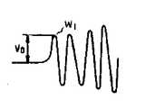
제12도는 전술한 각 재료로 이루어지는 재료 I를 표시펜의 선단부에 채용하고, 유리재(1)에 탄성파를 방출한 경우의 검출부(2a)(압전소자)에서 수신했을 때의 수신전압을 나타낸다. 단, 수신파는 종파 탄성파이고, 또한 그 선두파이다. 제13도에 종파탄성파의 검출신호를 나타내고, 그 선두파 W1의 피크치v0가 수신전압으로 된다.FIG. 12 shows the reception voltage when the material I made of the above-described materials is employed at the tip of the display pen and is received by the detection section 2a (piezoelectric element) when the elastic material is emitted to the glass material 1. However, the received wave is a longitudinal wave elastic wave and is also a leading wave. First shows the detection signal of the longitudinal acoustic wave in Figure 13, is the leading wave peak valuev0 of the W1 is the received voltage.
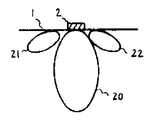
그리고, 탄성파검출부를 압전세라믹 등으로 이루어지는 고체진동 소자로 구성한 경우의 지향특성을 제14도에 나타낸다. 투명판(1)의 측면(코너부는 아님)에 탄성파검출부로서의 고체진동소자(2)를 부착한 경우, 지향성의 영향으로 이 소자로부터 등거리의 위치로부터 탄성파를 방사해도, 이 소자에서의 검출파형의 진폭은 반드시 동일하지 않고, 검도분포(20)에 의하면 진동소자(2)에 수직방향이 가장 감도가 높다. 이것이 지향성이 주축방향이다. 또한, 분포(21), (22)는 사이 드로프라고 불리는 감도분포를 나타낸다.14 shows the directivity characteristics when the acoustic wave detection unit is composed of a solid vibration element made of piezoelectric ceramics or the like. When the solid
제15도는 투명판의 측면에 부착한 고체진동소자(2)의 위치를 각각 이 소자(2)의 지향성의 주축이 투명판(1)의 중심으로 향하고 있지않을 경우의 감도분포 측정결과이다. 제16도는 진동소자(2)의 위치를 투명판(1)의 코너부에 부착하고, 또한 그 지향성의 주축이 투명판(1)의 중심으로 향하고 있을 경우의 감도분포 측정결과이다. 값v1,v2,v3…은 검출파형의 진폭전압이다.FIG. 15 shows the sensitivity distribution measurement results when the positions of the
제15도에 의하면, 진동소자(2)에서 등거리의 점 P와 Q를 진동원(振動源)으로 한 경우, 검출파형은v1과v6로 되고,v1≠v6이고, P점과 Q점과는 진동소자(2)로부터의 거리는 다른 것으로서 산출된다. 다른 점에 대해서도 마찬가지이다.According to FIG. 15, when the
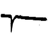
제17도는 제15도의 P,Q점에 대한 수신파형의 일예를 나타낸다.FIG. 17 shows an example of a reception waveform with respect to P and Q points of FIG.
Q점에 의한 수신파형은 P점의 수신파형에 비해 그 선두파는 작다. 검출파형의 한계치를 Vth라고 하면, Q점에 대해서는 선두파에서는 취할 수 없으며, 제 2 파에서 취한다. 이 결과, 송파(送波)펄스의 발생으로부터 수파(受波)까지의 시간(지연시간 또는 전파시간)은 Ta, Tb(Ta〉Tb)로 되어서, 잘못된 위치계측으로 된다.The reception waveform at Q point is smaller than the reception waveform at P point. If the threshold value of the detection waveform is set to Vth , the Q wave cannot be taken from the first wave, but taken from the second wave. As a result, the time (delay time or propagation time) from the generation of the wave pulse to the wave is Ta, Tb (Ta > Tb), resulting in incorrect position measurement.
한편, 제16도에 의하면, 중심방향으로 지향특성을 갖기 때문에, 거리의 변화에 의해서만 진폭이 변화하므로 제15도와 같은 경우는 발생하지 않는다. 그래서, 제16도에 나타낸 바와같이 코너부를 절단하고, 그 코너부에 진동소자(2)를 부착했다.On the other hand, according to Fig. 16, since the amplitude is changed only by the change of the distance because it has the directing characteristic in the center direction, the case like Fig. 15 does not occur. Therefore, as shown in FIG. 16, the corner part was cut | disconnected and the vibrating
제18도는 검출부(2)를 투명판(1)의 표면에 설치한 실시예이다. 이 경우에는, 검출부로서의 압전소자의 경방향의 공진주파수를 사용하는 것이 효과적이다. 특히, 투명판(1)의 두께가 얇은 경우에 효과가 있다.18 is an embodiment in which the
그리고, 어느 경우에도 사용하는 압전소자는 두께방향과 경방향의 공진주파수의 차가 큰 쪽이 효과적이다. 양자의 주파수가 근사할 경우에는 양파의 간섭에 의해 어느 쪽도 소정의 공진주파수가 얻어지지 않기 때문이다.In any case, the larger the difference between the resonant frequency in the thickness direction and the radial direction is, the more effective the piezoelectric element used is. This is because when the frequencies of both are approximated, neither of the resonance frequencies can be obtained due to onion interference.
상기 실시예에서는, 표시부(9)와의 결합의 사례이지만, 제19도와 같이 위치표정결과는 반드시 표시할 필요는 없으며, 계산기 등에 입력시켜도 된다. 따라서, 단순한 입력장치로서의 기능을 하게 된다.In the above embodiment, it is an example of coupling with the display unit 9, but the positioning results are not necessarily displayed as shown in FIG. 19, and may be input to a calculator or the like. Therefore, it functions as a simple input device.
또한, 투명판(1)에 대신에 불투명판이라도 된다.In addition, an opaque plate may be used instead of the transparent plate 1.
상기 선두파검출회로(5)에 입력된 종파초음파가 입력펜(3)의 경사 각도에 따라 변화하는 상황을 제20도에 나타낸다. 이 도면은 기입용 투명평판(1)의 양단에 종파검출부 A 및 B를 설치하고, 그 중간점 P으로부터 입력펜(3)에 의해 종파초음파가 입사된 때의 앙 수파자(受波子)에서 검출되는 파형을 나타낸다. (a)는 입력펜(3)을 수직으로 놓았을 때의 검출파형을 나타내고, 제 1 도착파 F는 검출부 A 및 B에 동위상으로 검출된다. 이것에 대해, (b), (c), (d)는 입력펜(3)을 검출부 A측으로 서서히 경사해 갔을 때의 검출파형을 나타낸다. 검출부 B에 있어서의 제 1도착과 F는 약간의 레벨변화가 있지만 위상적 변화는 볼 수 없는데 대해, 검출부 A에 있어서의 제 1도착과 F는 레벨의 변화와 함께 위상이 변화하고, 경사각이 큰 (d)에서는 위상이 반전한다. 따라서, 제 1 도착과 F에 착안하여 전파시간을 계측할 경우, 예를들어 피크점에 착안한 경우에 경사각 θ에 따라 전파시간이 변동하게 되어서, 위치표정오차의 요인으로 된다.20 shows a situation in which the longitudinal wave ultrasonic waves inputted to the head
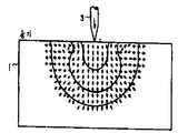
펜을 경사시켰을 경우에, 검출파의 파형이 변화하는 현상은 매체(1)에 입사된 초음파의 매체면에 평행인 성분이 입력펜의 경사의 영향을 받고 있기 때문인 것이 시뮬레이션에 의한 해석으로 증명된다. 그 결과를 제21도에 나타낸다. 제21(a)도와 같이 입력펜(3)의 매체(1)면에 수직일 경우에는 매체(1)내에서 퍼지는 파의 위상은 펜(3)을 중심으로 하여 대칭인 것을 알 수 있다. 그러나, 제21(b)도와 같이 입력펜(3)이 경사지면, 펜(3)이 경사진 쪽의 매체(1)의 표면 부근의 영역으로 파의 위상이 역전하여, 위상이 펜을 중심으로 하여 비대칭으로 된다는 것을 알 수 있다. 그리고, 상세히 해석하면 이 위상이 역전하는 영역은 입력펜(3)의 경사가 커짐에 따라 확대되어 간다. 이것으로부터, 입력펜(3)의 경사, 즉 매체(1)에 입사하는 초음파의 매체면에 평행인 성분이 매체내의 매체면에 평행인 파성분(波成分)의 위상에 직접 영향을 미치고 있을 것을 알 수 있다. 이 현상으로 인해, 펜이 경사지면 검출파의 파형이 변화하는 것이다.When the pen is inclined, the phenomenon in which the waveform of the detection wave changes is proved by simulation analysis that the component parallel to the medium surface of the ultrasonic wave incident on the medium 1 is affected by the inclination of the input pen. . The result is shown in FIG. As shown in FIG. 21 (a), when the surface of the
그러나, 잘 주의해 보면, 펜이 경사진 쪽의 위상이 모두 역전되어 있는 것은 아니라는 것을 알 수 있다. 즉, 초음파의 입사점 아래쪽의 매체 표면으로부터 깊은 곳, 특히 파의 위상을 나타내는 화살표의 소용돌이가 생기고 있는 깊이 이하에서의 파의 위상은 펜을 중심으로 하여 대칭으로 되어 있는 것이다. 이것으로부터, 이 위상이 대칭인 파를 비대칭인 파보다 빨리 검출소자에 유도할 수 있으면, 펜의 경사의 영향을 저감할 수 있어서, 검출하의 파형변화, 특히 위상의 역전을 방지할 수 있다.However, if you look carefully, you can see that the pen's inclined phase is not all reversed. In other words, the phase of the wave deep below the surface of the medium below the point of incidence of the ultrasonic wave, particularly below the depth at which the vortex of the arrow indicating the phase of the wave is generated, is symmetrical around the pen. From this, if the wave having the symmetrical phase can be guided to the detection element earlier than the asymmetrical wave, the influence of the inclination of the pen can be reduced, and the waveform change under detection, in particular, the reversal of the phase can be prevented.
본원 발명은 전술한 바와같은 지견에 의해 생긴 것으로서, 그 실시예를 제22도에 나타낸다. 상기 기입장치(1)에 있어서, 기입판(1)을 최소한 2층으로 이루어지는 구조로하고, 초음파를 전반(傳搬)시키는 전반층매체(1a)상에 이 전반층매체보다 종파속도가 느린 재질로 이루어지는 입력층매체(1b)를 배설하고, 상기 전반층매체(1a)측에 검출소자(2a), (2b), (2c), (2d)를 부착한 구조로 한다.The present invention is produced by the above-described knowledge, and the embodiment thereof is shown in FIG. In the writing device 1, the writing plate 1 has a structure composed of at least two layers, and the longitudinal wave speed is slower than that of the first layer medium on the first layer medium 1a that propagates ultrasonic waves. The input layer medium 1b is formed, and the
제22도는 본원 발명의 일실시예에 의한 효과를 시뮬레이션에 의해 확인한 도면이다. 이 해석에서 사용한 재료는 표 1에 나타낸 것이다. 제22도로부터 매체를 2층화하면 펜이 경사진 경우에도 위상이 대칭화된 영역이 생긴다. 그리고, 상세한 해석에 의해 이 위상이 대칭화된 동상(同相)영역은 펜(3)의 경사를 일정하게 한 경우는 음파가 느린 입력층이 두꺼워짐에 따라 커지며, 또 입력층의 두께를 일정하게 한 경우는 펜의 경사가 작을수록 동상영역이 커지나, 대략 반파장의 길이로 되면 그 이후는 입력층을 두껍게 해도 동상영역의 증가는 볼 수 없는 것을 알았다. 이것으로부터, 입력층의 두께는 함부로 두껍게 할 필요는 없는 것을 알았다. 또한, 입력층의 음파를 느리게하면 같은 효과를 얻기 위한 층의 두께는 얇게 할 수 있는 것도 알았다.22 is a diagram confirming the effects of the embodiment of the present invention by a simulation. The materials used in this analysis are shown in Table 1. Double layering of media from FIG. 22 results in an area symmetrical in phase even when the pen is inclined. In the in-depth region where the phase is symmetrical by detailed analysis, when the inclination of the
실용면에서 생각하면, 실용상의 최대의 펜 경사시에 있어서, 이 위상이 대칭화된 동상영역의 크기가 전반층에서의 초음파의 파장의 절반이면 된다고 할 수 있다. 이것으로부터, 음파가 느린 입력층의 두께가 결정된다. 구체적으로는, 초음파의 주파수가 400KHz에서 표 1의 재료를 사용한 경우, 입력펜의 최대경사가 40°이면 입력층의 두께는 1.2mm이면 되고, 최대경사가 30°이면 입력층의 두께가 0.8mm이면 되는 것을 알았다.In practical terms, it can be said that at the maximum pen tilt in practical use, the size of the in-phase region in which this phase is symmetric is only half of the wavelength of the ultrasonic wave in the first layer. From this, the thickness of the input layer with slow sound waves is determined. Specifically, when the ultrasonic wave frequency is 400 KHz, the material of Table 1 is used. If the maximum inclination of the input pen is 40 °, the thickness of the input layer should be 1.2 mm. If the maximum inclination is 30 °, the thickness of the input layer is 0.8 mm. I knew it was good.
[표 2]TABLE 2
해석에 사용한 재료의 밀도와 음속Density and Sound Velocity of the Material Used in the Analysis

전술한 바와같이 타블렛을 구성함으로써, 펜의 경사에 의한 파형변동을 저감하고, 특히 위상의 역전을 방지할 수 있게 되어서, 고정밀도로 위치평정(位置評定)할 수 있는 초음파응용 타블렛을 실현할 수 있다.By constructing the tablet as described above, it is possible to reduce waveform fluctuations due to the inclination of the pen, to prevent phase reversal in particular, and to realize an ultrasonic application tablet which can be accurately positioned.
또한, 표 2에 나타낸 재료는 투명하며, 이와같은 투명한 재료로 구성한 타블렛을 액정표시장치나 CRT등의 표시면에 적층하면, 입력면과 표시면을 일체화한 초음파응용 타블렛을 실현할 수 있는 잇점이 있다. 투명한 재료로 종파속도가 다른 재료는 많이 있으며, 그들의 조합이 가능하다. 또한, 동일 재료로 음향적으로 2층으로 되어 있는 재료를 사용해도 같은 효과를 얻을 수 있다.In addition, the material shown in Table 2 is transparent, and if a tablet composed of such a transparent material is laminated on a display surface such as a liquid crystal display device or a CRT, an ultrasonic application tablet in which the input surface and the display surface are integrated can be realized. . There are many materials with different longitudinal velocities, and they can be combined. In addition, the same effect can be obtained also when using the material which consists of two layers acoustically from the same material.
이상은 투명한 기입판에 대해 기술하였지만, 물론 불투명한 재료로도 효과적으로는 전혀 동일하다. 예를들면, 상기 전반층매체로서 알루미늄(종파속도 : 6260m/s)을 사용하고, 입력층매체로서 베이클라이트(종파속도 : 2590m/s)를 사용함으로써, 펜의 경사의 영향을 없앨 수 있다.Although the above has been described for the transparent writing board, of course, the opaque material is effectively the same as well. For example, by using aluminum (long wave speed: 6260 m / s) as the first layer medium and bakelite (long wave speed: 2590 m / s) as the input layer medium, the influence of the inclination of the pen can be eliminated.
다음에, 다른 실시예에 대해 설명한다. 제24도는 기입장치의 복합화 구조의 응용을 나타낸 것으로서, 기입판(1)의 전반층매체(1a)와 입력층매체(1b)의 중감에 중간층매체(1c)를 배설하고, 이 중간층매체(1c)로서 종파속도가 상기 전반층매체(1a)와 상기 입력층매체(1b)의 종파속도의 중간의 속도를 갖는 것을 사용하는 것을 특징으로 하고 있다. 효과는 제22도의 실시예와 같다.Next, another Example is described. FIG. 24 shows the application of the composite structure of the writing apparatus. The intermediate layer medium 1c is disposed in the middle of the first layer medium 1a and the input layer medium 1b of the writing plate 1, and the intermediate layer medium 1c. ) Is characterized in that the longitudinal wave velocity has a speed in the middle of the longitudinal wave velocity of the first layer medium 1a and the input layer medium 1b. The effect is the same as in the embodiment of FIG.
또한, 제25도는 상기 2개의 실시예와 다르고, 입력펜(3)에 개량을 가한 것이다. 이 도면의 확대도 제26도에 나타낸 바와같이, 입력펜(3)의 선단부의 펜끝(12)에 접촉용 소편(12a)을 부착하고, 이 접촉용 소편재로서 증파속도가 싱가 기입판(1)의 종파속도보다 느린 재료를 사용하는 것을 특징으로 한다. 이 경우, 펜끝(12)의 재질로서는 그 종파속도가 상기 접촉용 소편의 종파속도보다 빠른 것을 사용하는 것이 바람직하다. 이상 본 실시예도 효과적으로는 제22도의 경우와 같으며, 입력펜의 경사의 영향을 없앨 수 있다.25 is different from the above two embodiments, and the
그리고, 전술한 복합화 기입판은 음속이 다른 복수의 판을 맞붙이는 방법, 예를들면 유리판 위에 폴리카보네이트판과 아크릴판 등을 맞붙이는 합판방법에 의해 제조된다. 또한, 다른 방법으로서, 동일재에 있어서 제조과정에서 소재의 물리적 성질, 예를들면 비중의 차이등을 이용하여 음향특성상 2층화 매체를 만들어 제조된다.The composite writing board described above is produced by a method of bonding a plurality of plates having different sound speeds, for example, a plywood method of pasting a polycarbonate plate and an acrylic plate on a glass plate. As another method, the same material is manufactured by making a two-layered medium in terms of acoustic characteristics using the physical properties of the material, for example, the difference in specific gravity, in the manufacturing process.
Claims (11)
Translated fromKoreanApplications Claiming Priority (8)
| Application Number | Priority Date | Filing Date | Title |
|---|---|---|---|
| JP15311284AJPS6133524A (en) | 1984-07-25 | 1984-07-25 | Position orientation device using elastic wave |
| JP84-153112 | 1984-07-25 | ||
| JP15311884AJPS6133525A (en) | 1984-07-25 | 1984-07-25 | Position orientation device using elastic wave |
| JP84-153111 | 1984-07-25 | ||
| JP84-153118 | 1984-07-25 | ||
| JP15311184AJPS6133523A (en) | 1984-07-25 | 1984-07-25 | Position orienting device utilizing elastic wave |
| JP84-220971 | 1984-10-19 | ||
| JP59220971AJPS6198433A (en) | 1984-10-19 | 1984-10-19 | Tablet type coordinate input device using elastic waves |
Publications (2)
| Publication Number | Publication Date |
|---|---|
| KR860001375A KR860001375A (en) | 1986-02-26 |
| KR930003168B1true KR930003168B1 (en) | 1993-04-23 |
Family
ID=27473205
Family Applications (1)
| Application Number | Title | Priority Date | Filing Date |
|---|---|---|---|
| KR1019850005072AExpired - Fee RelatedKR930003168B1 (en) | 1984-07-25 | 1985-07-16 | Input device of tablet type |
Country Status (1)
| Country | Link |
|---|---|
| KR (1) | KR930003168B1 (en) |
Families Citing this family (1)
| Publication number | Priority date | Publication date | Assignee | Title |
|---|---|---|---|---|
| JPH11110133A (en)* | 1997-10-01 | 1999-04-23 | Daicel Chem Ind Ltd | Touch sensor glass substrate, and touch panel |
- 1985
- 1985-07-16KRKR1019850005072Apatent/KR930003168B1/ennot_activeExpired - Fee Related
Also Published As
| Publication number | Publication date |
|---|---|
| KR860001375A (en) | 1986-02-26 |
Similar Documents
| Publication | Publication Date | Title |
|---|---|---|
| EP0169538B1 (en) | Tablet type coordinate input apparatus using elastic waves | |
| US5379269A (en) | Position determining apparatus | |
| EP0435203B1 (en) | Coordinate input apparatus | |
| CA1207883A (en) | Graphical data apparatus | |
| US4488000A (en) | Apparatus for determining position and writing pressure | |
| US3692936A (en) | Acoustic coordinate data determination system | |
| EP0656603B1 (en) | Piezoelectric sensor and coordinate input apparatus employing the same | |
| JPH0475536B2 (en) | ||
| KR930003168B1 (en) | Input device of tablet type | |
| Kang et al. | Feasibility study on multi-touch ultrasound large-panel touchscreen using guided lamb waves | |
| EP0107922A1 (en) | Graphical data apparatus | |
| JPH1115592A (en) | Position input device | |
| EP0367282A2 (en) | Coordinate input apparatus | |
| JPS6198433A (en) | Tablet type coordinate input device using elastic waves | |
| JPS6133523A (en) | Position orienting device utilizing elastic wave | |
| JPS61281324A (en) | Ultrasonic application tablet | |
| Nikolovski et al. | 250 DPI at 1000 Hz acquisition rate S 0 lamb wave digitizing pen | |
| JP2002342031A (en) | Ultrasonic touch panel | |
| JPS6083126A (en) | Coordinate detector for input position | |
| JPS6133524A (en) | Position orientation device using elastic wave | |
| JPS62165107A (en) | Ultrasonic position detector | |
| JP3258433B2 (en) | Vibration detector | |
| CN85106123A (en) | Chip type coordinate input device using elastic wave | |
| JP2004046500A (en) | Ultrasonic touch panel and method of calculating position of ultrasonic touch panel | |
| JPH09170947A (en) | Ultrasonic receiving unit and ultrasonic coordinate input device |
Legal Events
| Date | Code | Title | Description |
|---|---|---|---|
| PA0109 | Patent application | St.27 status event code:A-0-1-A10-A12-nap-PA0109 | |
| R17-X000 | Change to representative recorded | St.27 status event code:A-3-3-R10-R17-oth-X000 | |
| PG1501 | Laying open of application | St.27 status event code:A-1-1-Q10-Q12-nap-PG1501 | |
| A201 | Request for examination | ||
| PA0201 | Request for examination | St.27 status event code:A-1-2-D10-D11-exm-PA0201 | |
| P11-X000 | Amendment of application requested | St.27 status event code:A-2-2-P10-P11-nap-X000 | |
| P13-X000 | Application amended | St.27 status event code:A-2-2-P10-P13-nap-X000 | |
| PA0201 | Request for examination | St.27 status event code:A-1-2-D10-D11-exm-PA0201 | |
| R17-X000 | Change to representative recorded | St.27 status event code:A-3-3-R10-R17-oth-X000 | |
| E902 | Notification of reason for refusal | ||
| PE0902 | Notice of grounds for rejection | St.27 status event code:A-1-2-D10-D21-exm-PE0902 | |
| P11-X000 | Amendment of application requested | St.27 status event code:A-2-2-P10-P11-nap-X000 | |
| P13-X000 | Application amended | St.27 status event code:A-2-2-P10-P13-nap-X000 | |
| G160 | Decision to publish patent application | ||
| PG1605 | Publication of application before grant of patent | St.27 status event code:A-2-2-Q10-Q13-nap-PG1605 | |
| E701 | Decision to grant or registration of patent right | ||
| PE0701 | Decision of registration | St.27 status event code:A-1-2-D10-D22-exm-PE0701 | |
| GRNT | Written decision to grant | ||
| PR0701 | Registration of establishment | St.27 status event code:A-2-4-F10-F11-exm-PR0701 | |
| PR1002 | Payment of registration fee | St.27 status event code:A-2-2-U10-U11-oth-PR1002 Fee payment year number:1 | |
| PR1001 | Payment of annual fee | St.27 status event code:A-4-4-U10-U11-oth-PR1001 Fee payment year number:4 | |
| PR1001 | Payment of annual fee | St.27 status event code:A-4-4-U10-U11-oth-PR1001 Fee payment year number:5 | |
| FPAY | Annual fee payment | Payment date:19980325 Year of fee payment:6 | |
| PR1001 | Payment of annual fee | St.27 status event code:A-4-4-U10-U11-oth-PR1001 Fee payment year number:6 | |
| R18-X000 | Changes to party contact information recorded | St.27 status event code:A-5-5-R10-R18-oth-X000 | |
| PN2301 | Change of applicant | St.27 status event code:A-5-5-R10-R13-asn-PN2301 St.27 status event code:A-5-5-R10-R11-asn-PN2301 | |
| LAPS | Lapse due to unpaid annual fee | ||
| PC1903 | Unpaid annual fee | St.27 status event code:A-4-4-U10-U13-oth-PC1903 Not in force date:19990424 Payment event data comment text:Termination Category : DEFAULT_OF_REGISTRATION_FEE | |
| PC1903 | Unpaid annual fee | St.27 status event code:N-4-6-H10-H13-oth-PC1903 Ip right cessation event data comment text:Termination Category : DEFAULT_OF_REGISTRATION_FEE Not in force date:19990424 | |
| R17-X000 | Change to representative recorded | St.27 status event code:A-5-5-R10-R17-oth-X000 | |
| R18-X000 | Changes to party contact information recorded | St.27 status event code:A-5-5-R10-R18-oth-X000 | |
| P22-X000 | Classification modified | St.27 status event code:A-4-4-P10-P22-nap-X000 | |
| P22-X000 | Classification modified | St.27 status event code:A-4-4-P10-P22-nap-X000 |