KR930001285B1 - Wafer Transfer Method, Apparatus and Control Device for Vertical CVD Diffusion Equipment - Google Patents
Wafer Transfer Method, Apparatus and Control Device for Vertical CVD Diffusion EquipmentDownload PDFInfo
- Publication number
- KR930001285B1 KR930001285B1KR1019900000180AKR900000180AKR930001285B1KR 930001285 B1KR930001285 B1KR 930001285B1KR 1019900000180 AKR1019900000180 AKR 1019900000180AKR 900000180 AKR900000180 AKR 900000180AKR 930001285 B1KR930001285 B1KR 930001285B1
- Authority
- KR
- South Korea
- Prior art keywords
- wafer
- transfer
- control unit
- wafers
- cassette
- Prior art date
- Legal status (The legal status is an assumption and is not a legal conclusion. Google has not performed a legal analysis and makes no representation as to the accuracy of the status listed.)
- Expired - Lifetime
Links
- 238000012546transferMethods0.000titleclaimsdescription65
- 238000000034methodMethods0.000titleclaimsdescription21
- 238000009792diffusion processMethods0.000titleclaimsdescription16
- 235000012431wafersNutrition0.000claimsdescription190
- 238000003860storageMethods0.000claimsdescription25
- 230000007246mechanismEffects0.000claimsdescription18
- 230000008859changeEffects0.000claimsdescription4
- 239000000758substrateSubstances0.000description12
- 238000005229chemical vapour depositionMethods0.000description11
- 239000011295pitchSubstances0.000description11
- 230000033001locomotionEffects0.000description8
- 238000010586diagramMethods0.000description6
- 239000003638chemical reducing agentSubstances0.000description5
- 230000008569processEffects0.000description4
- 238000001179sorption measurementMethods0.000description3
- XLYOFNOQVPJJNP-UHFFFAOYSA-NwaterSubstancesOXLYOFNOQVPJJNP-UHFFFAOYSA-N0.000description3
- 230000008901benefitEffects0.000description2
- 238000009826distributionMethods0.000description2
- 238000003780insertionMethods0.000description2
- 230000037431insertionEffects0.000description2
- 238000012545processingMethods0.000description2
- CCEKAJIANROZEO-UHFFFAOYSA-NsulfluramidChemical groupCCNS(=O)(=O)C(F)(F)C(F)(F)C(F)(F)C(F)(F)C(F)(F)C(F)(F)C(F)(F)C(F)(F)FCCEKAJIANROZEO-UHFFFAOYSA-N0.000description2
- XUIMIQQOPSSXEZ-UHFFFAOYSA-NSiliconChemical compound[Si]XUIMIQQOPSSXEZ-UHFFFAOYSA-N0.000description1
- 230000002411adverseEffects0.000description1
- 238000005520cutting processMethods0.000description1
- 230000000694effectsEffects0.000description1
- 230000001747exhibiting effectEffects0.000description1
- 238000007689inspectionMethods0.000description1
- 238000004519manufacturing processMethods0.000description1
- 238000012544monitoring processMethods0.000description1
- 230000010355oscillationEffects0.000description1
- 230000009467reductionEffects0.000description1
- 239000004065semiconductorSubstances0.000description1
- 229910052710siliconInorganic materials0.000description1
- 239000010703siliconSubstances0.000description1
- 229940095676wafer productDrugs0.000description1
Images


Classifications
- H—ELECTRICITY
- H01—ELECTRIC ELEMENTS
- H01L—SEMICONDUCTOR DEVICES NOT COVERED BY CLASS H10
- H01L21/00—Processes or apparatus adapted for the manufacture or treatment of semiconductor or solid state devices or of parts thereof
- H01L21/02—Manufacture or treatment of semiconductor devices or of parts thereof
- H01L21/04—Manufacture or treatment of semiconductor devices or of parts thereof the devices having potential barriers, e.g. a PN junction, depletion layer or carrier concentration layer
- H01L21/18—Manufacture or treatment of semiconductor devices or of parts thereof the devices having potential barriers, e.g. a PN junction, depletion layer or carrier concentration layer the devices having semiconductor bodies comprising elements of Group IV of the Periodic Table or AIIIBV compounds with or without impurities, e.g. doping materials
- H01L21/30—Treatment of semiconductor bodies using processes or apparatus not provided for in groups H01L21/20 - H01L21/26
- C—CHEMISTRY; METALLURGY
- C23—COATING METALLIC MATERIAL; COATING MATERIAL WITH METALLIC MATERIAL; CHEMICAL SURFACE TREATMENT; DIFFUSION TREATMENT OF METALLIC MATERIAL; COATING BY VACUUM EVAPORATION, BY SPUTTERING, BY ION IMPLANTATION OR BY CHEMICAL VAPOUR DEPOSITION, IN GENERAL; INHIBITING CORROSION OF METALLIC MATERIAL OR INCRUSTATION IN GENERAL
- C23C—COATING METALLIC MATERIAL; COATING MATERIAL WITH METALLIC MATERIAL; SURFACE TREATMENT OF METALLIC MATERIAL BY DIFFUSION INTO THE SURFACE, BY CHEMICAL CONVERSION OR SUBSTITUTION; COATING BY VACUUM EVAPORATION, BY SPUTTERING, BY ION IMPLANTATION OR BY CHEMICAL VAPOUR DEPOSITION, IN GENERAL
- C23C16/00—Chemical coating by decomposition of gaseous compounds, without leaving reaction products of surface material in the coating, i.e. chemical vapour deposition [CVD] processes
- C23C16/44—Chemical coating by decomposition of gaseous compounds, without leaving reaction products of surface material in the coating, i.e. chemical vapour deposition [CVD] processes characterised by the method of coating
- C23C16/54—Apparatus specially adapted for continuous coating
- H—ELECTRICITY
- H01—ELECTRIC ELEMENTS
- H01L—SEMICONDUCTOR DEVICES NOT COVERED BY CLASS H10
- H01L21/00—Processes or apparatus adapted for the manufacture or treatment of semiconductor or solid state devices or of parts thereof
- H01L21/67—Apparatus specially adapted for handling semiconductor or electric solid state devices during manufacture or treatment thereof; Apparatus specially adapted for handling wafers during manufacture or treatment of semiconductor or electric solid state devices or components ; Apparatus not specifically provided for elsewhere
- H01L21/677—Apparatus specially adapted for handling semiconductor or electric solid state devices during manufacture or treatment thereof; Apparatus specially adapted for handling wafers during manufacture or treatment of semiconductor or electric solid state devices or components ; Apparatus not specifically provided for elsewhere for conveying, e.g. between different workstations
- H01L21/67763—Apparatus specially adapted for handling semiconductor or electric solid state devices during manufacture or treatment thereof; Apparatus specially adapted for handling wafers during manufacture or treatment of semiconductor or electric solid state devices or components ; Apparatus not specifically provided for elsewhere for conveying, e.g. between different workstations the wafers being stored in a carrier, involving loading and unloading
- H01L21/67778—Apparatus specially adapted for handling semiconductor or electric solid state devices during manufacture or treatment thereof; Apparatus specially adapted for handling wafers during manufacture or treatment of semiconductor or electric solid state devices or components ; Apparatus not specifically provided for elsewhere for conveying, e.g. between different workstations the wafers being stored in a carrier, involving loading and unloading involving loading and unloading of wafers
- H01L21/67781—Batch transfer of wafers
- Y—GENERAL TAGGING OF NEW TECHNOLOGICAL DEVELOPMENTS; GENERAL TAGGING OF CROSS-SECTIONAL TECHNOLOGIES SPANNING OVER SEVERAL SECTIONS OF THE IPC; TECHNICAL SUBJECTS COVERED BY FORMER USPC CROSS-REFERENCE ART COLLECTIONS [XRACs] AND DIGESTS
- Y10—TECHNICAL SUBJECTS COVERED BY FORMER USPC
- Y10S—TECHNICAL SUBJECTS COVERED BY FORMER USPC CROSS-REFERENCE ART COLLECTIONS [XRACs] AND DIGESTS
- Y10S414/00—Material or article handling
- Y10S414/135—Associated with semiconductor wafer handling
- Y10S414/141—Associated with semiconductor wafer handling includes means for gripping wafer
Landscapes
- Engineering & Computer Science (AREA)
- Chemical & Material Sciences (AREA)
- Computer Hardware Design (AREA)
- Condensed Matter Physics & Semiconductors (AREA)
- Power Engineering (AREA)
- Microelectronics & Electronic Packaging (AREA)
- Manufacturing & Machinery (AREA)
- General Physics & Mathematics (AREA)
- Physics & Mathematics (AREA)
- Metallurgy (AREA)
- Organic Chemistry (AREA)
- Chemical Kinetics & Catalysis (AREA)
- General Chemical & Material Sciences (AREA)
- Mechanical Engineering (AREA)
- Materials Engineering (AREA)
- Container, Conveyance, Adherence, Positioning, Of Wafer (AREA)
Abstract
Translated fromKoreanDescription
Translated fromKorean제1도는 본 발명에 관련한 이송장치를 구비한 세로형 CVD 확산장치의 개략 설명도.1 is a schematic explanatory diagram of a vertical CVD diffuser with a transfer device in accordance with the present invention.
제2도는 제1도의 전면 외관도.2 is a front exterior view of FIG.
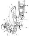
제3도는 핸들링 유니트의 분해사시도.3 is an exploded perspective view of the handling unit.
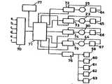
제4도는 본 발명에 관련한 제어장치의 개략 블록도.4 is a schematic block diagram of a control device according to the present invention.
제5도~제9도는 이송동작설명도.5 to 9 are diagrams illustrating the transfer operation.
제10도는 웨이퍼 척(chuck)의 다른 예를 나타낸 설명도.10 is an explanatory diagram showing another example of a wafer chuck.
제11도는 보우트에 대한 웨이퍼 배열의 일예를 나타낸 도면.11 illustrates an example of a wafer arrangement for a boat.
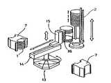
제12도는 웨이퍼 이송장치의 종래예의 설명도.12 is an explanatory diagram of a conventional example of a wafer transfer apparatus.
제13도는 제12도의 다른 종래예의 설명도.13 is an explanatory diagram of another conventional example of FIG.
* 도면의 주요부분에 대한 부호의 설명* Explanation of symbols for main parts of the drawings
1.1a,1b,1c : 웨이퍼 2 :보우트1.1a, 1b, 1c: wafer 2: boat
7,7a,7b,7c : 카세트 12 : 화산로7,7a, 7b, 7c: cassette 12: volcano
17 : 로우드 언로우드 엘리베이터 18 : 이송용 엘리베이터17: low-unlock elevator 18: transfer elevator
23 :승강 모우터 25 : 가로행 모우터23: lifting motor 25: horizontal row motor
28 : 슬라이드기구 29 : 웨이퍼 척28: slide mechanism 29: wafer chuck
30 : 회전 모우터 53,54.55.56,57 : 척 플레이트30:
59,60,61,62,63 : 전자밸브 70 : 입력부59, 60, 61, 62, 63: solenoid valve 70: input
71 : 주제어부 73 : 승강 모우터 제어부71: main controller 73: lifting motor control unit
74 : 회전모우터 제어부 15 : 슬라이드 모우터 제어부74: rotation motor control unit 15: slide motor control unit
76 : 전자밸브 제어부를 표시함76: Display solenoid valve control unit
본 발명은 세로형 CVD 확산장치에 있어서의 웨이퍼의 이송에 관한 것이다.The present invention relates to the transfer of wafers in a vertical CVD diffuser.
반도체 소자의 제조프로세스의 하나에 CVD처리가 있다. 이것은 소요매수의 실리콘의 웨이퍼를 CVD장치 내에서 가열하고 화학기상 퇴적(CVD) 시키는 것이지만 CVD처리의 균질화를 도모하기 위해 제품을 웨이퍼 를 사이에 끼는 것처럼 열의 양단부에는 각 복수매의 더미 웨이퍼가 배열되어 있고, 더욱이 제품용 웨이퍼의 도중, 소요의 간격으로 검사용의 모니터 웨이퍼가 각 1매 배열되어 있다. 이것을 제11도에 의하여 대략 설명한다.One process for manufacturing semiconductor devices is CVD. This is to heat the required number of silicon wafers in a CVD apparatus and chemical vapor deposition (CVD), but a plurality of dummy wafers are arranged at both ends of the column, such as sandwiching the product between the wafers for the purpose of homogenizing the CVD process. In addition, one monitor wafer for inspection is arranged at intervals required during the product wafer. This is roughly explained by FIG.
확산로에서는 웨이퍼(1)는 보우트(2)에 의하여 지지되도록 되어 있고, 확산로에 웨이퍼(1)을 CVD처리하는 경우에는 우선 보우트(2)에 웨이퍼(1)가 소요의 배열이 되도록 삽입하고 웨이퍼(1)가 삽입된 보우트(2) 를 확산로내에 장입한다.In the diffusion path, the wafer 1 is supported by the
일반적으로 확산로내는 전역에 걸쳐서 균일한 온도분포에는 되어 있지 않고, 따라서 상기 보우트(2)에는 처리해야할 웨이퍼(1)수에 대하여 충분히 여유가 있는 수(예컨대 웨이퍼의 처리매수의 1.5배의 수)만큼의 웨이퍼 수납 스패이스를 구비하고 있고, 웨이퍼를 처리하는 경우는 온도 분포의 균일한 개소에 대응시켜 혹은 웨이퍼의 매수에 따라서 보우트(2)의 웨이퍼 수납위치를 선정하도록 되어 있다.In general, the diffusion furnace does not have a uniform temperature distribution over the entire area, so the
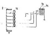
보우트(2)의 웨이퍼 배열의 상단부, 하단부에는 각각 적당한 수의 더미 웨이퍼 (1b)에서 이루어지는 더미 웨이퍼군(3,4)이 수납되고, 모니터 웨이퍼(1c)를 끼고 소정 매수의 제품용 웨이퍼(1a)에서 이루어지는 제 품용 웨이퍼군(5)이 수납되고 또한 모니터 웨이퍼(1c)를 끼고 순차 제품용 웨이퍼군(5)이 수납되어 있다. 최하부의 제품용 웨이퍼군(5)과 상기 더미 웨이퍼군(4)과의 사이에는 모니터 웨이퍼(1c)가 삽입되어 있다. 웨이퍼 이송장치는 카세트에 장진된 웨이퍼를 상기 보우트로 이송하고, 또 처리후의 웨이퍼를 빈 카세트에 장전하는 일련의 작업을 행하는 것이다.At the upper end and the lower end of the wafer array of the
종래의 웨이퍼 이송장치에 대하여 제12도에 있어서 설명한다.A conventional wafer transfer apparatus will be described with reference to FIG.
제12도에 도시되는 것은 매엽식(1매씩 이송하는 방식)의 웨이퍼 이송장치를 나타내고 있고, 핸들링 유니 트(6)외 주위에는 웨이퍼(1)가 장전된 카세트(7)가 동일 원주상에 소요수 배치되고, 또 핸들링 유니트(6)에 인접하여 이송용 엘리베이터(8), 로우드 ·언로우드 엘리베이터(9)가 설치되고 이송용 엘리베이터(8)의 보우트 받이대(10)는 상기 원주를 포함하는 원통면의 모선을 따라서 승 강하도록 되어 있고, 로우드·언로우드 엘리베이터(9)의 보우트 받이대(11)의 윗쪽에는 세로형 화산로(12)가 설치되어 있다. 또 이송용 엘리베이터 (8)와 로우드·언로우드 엘리베이터와의 사이에는 보우트 (2)의 시프트를 행하는 시프트 유니트(13)가 설치 되어 있다.Shown in FIG. 12 shows a wafer conveying apparatus of a sheet type (a sheet feeding method), and a
상기 핸들링 유니트(6)는 상기 원주의 중심을 중심으로 회전하고 또한 승강하는 회전아암(14)과 이 회전 아암(14)를 따라서 반경방향으로 진퇴하는 웨이퍼 흡착 척(15)을 구비하고 카세트(7)에 장전된 웨이퍼 (1)를 1매씩 흡착하여 꺼내고 이송용 엘리베이터(8)에 태워둔 보우트(2)에 윗측에서 순차로 이송해 간다. 이송용 엘리베이터(8)는 웨이퍼(1)의 이송의 진행에 추종하여 일단식 하강한다.The
웨이퍼(1)의 이송이 완료된 보우트(2)는 시프트 유니트(13)에 의하여 이송용 엘리베이터(8)에서 로우드 언로우드 엘리베이터(9)에 시프트되어 로우드·언로우드 엘리베이터(9)는 보우트(2)를 화산로(12)내에 장입 한다.The
CVD처리가 완료하면 보우트(2)가 확산로(12)에서 끄집어 내어지고, 더욱이 시프트 유니트(13)에 의하여 이송용 앨리베이터(8)에 시프트되고, 핸들링 유니트(6)에 의하여 상기한 역의 수순으로 카세트(7)에 장전된다.When the CVD process is completed, the
상기한 종래의 이송장치는 매엽식이었지만 제13도에 도시한 바와 같이 일괄식의 것도 있다. 이것은 웨이퍼 흡착 척(15)이 25조의 흡착 플레이트(16)을 구비하고 카세트(7)에 장전되어 있는 25매의 웨이퍼(1)를 전부 일괄하여 척킹하고 보우트(2)에 이송을 행하는 것이다.The conventional conveying apparatus described above was a sheet type, but there is also a batch type as shown in FIG. This is because the
그러나 상기한 종래의 매엽방식의 이송장치, 일괄방식의 이송장치에는 이하에 설명하는 바와 같은 불편이 있다.However, the above-mentioned conventional sheet feeding method and the batch type conveying apparatus have the inconvenience as described below.
상기한 보우트(2)에 삽입되는 웨이퍼의 배열, 상단, 하단의 더미 웨이퍼의 매수를 각 몇매로 할 것인가, 혹은 모니터 웨이퍼를 제품용 웨이퍼의 몇장째 마다에 또한 몇장 설치할 것인가는 처리를 행하는 조건, 혹은 고개의 처리방법에 따라서 다르다.The conditions under which the processing is performed are the number of sheets of the array of wafers inserted into the above-described
전자의 매엽방식은 웨이퍼를 1매씩 이송하여 감으로, 웨이퍼의 여하한 배열에도 대응할 수 있다. 그러나 동작 회수가 현저하게 많고, 그 때문에 이송시간이 길어지고 효율이 나쁘다. 또 동작회수가 많다고 하는 것 은 발진의 가능성이 확율적으로 증대하고 제품품질에 악영향을 준다.The former single sheet method can cope with any arrangement of wafers by transferring the wafers one by one. However, the number of operations is remarkably large, which results in a long transfer time and poor efficiency. Also, the high number of motions increases the probability of oscillation and adversely affects product quality.
이에 대하여 후자 일괄방식은 이송시간이 짧고 극히 능율적이라고 하는 이점은 있지만 25매 일괄로 처리 하고 있기 때문에 레이저 이송시에 웨이퍼의 배열을 정돈할 수가 없다. 따라서. 카세트에 웨이퍼를 장전하 는 때에 소정의 배열이 되도록, 더미 웨이퍼, 모니터 웨이퍼, 제품용 웨이퍼를 혼재시키도록 하고 있다. 카세트에의 웨이퍼의 장전작업은 수작업이고 종류가 다른 웨이퍼를 소정의 배열이 되도록 장전하는 작업은 대단히 번잡하고 비능률적이고 또 잘못 삽입도 피할 수 없는 것이 현상이었다.On the other hand, the latter batch method has the advantage that the transfer time is short and extremely efficient, but since the batch is processed in 25 sheets, the arrangement of wafers cannot be arranged during laser transfer. therefore. The dummy wafer, the monitor wafer, and the product wafer are mixed in a predetermined arrangement when loading the wafer into the cassette. Loading of wafers into a cassette is manual, and loading of wafers of different types into a predetermined arrangement is a phenomenon that is very complicated, inefficient, and inadvertent insertion is unavoidable.
이같은 실정을 감안하여 본 출원인은 먼저의 출원(실원소 62-130524호)에 있어서 5매의 웨이퍼를 한번에 이송하는 부분 일괄 이송방식의 웨이퍼 이송기를 제안하고 있지만 본 발명은 이부분 일괄 이송방식에 있어서 매엽방식의 장점과 일괄방식의 장점을 충분히 발휘시킬 수 있는 웨이퍼의 이송방법, 이송장치, 이송제어 장치를 제공하려고 하는 것이다.In view of such circumstances, the present applicant proposes a wafer transfer machine of a partial batch transfer method for transferring five wafers at a time in the previous application (real element 62-130524). An object of the present invention is to provide a wafer transfer method, a transfer device, and a transfer control device capable of fully exhibiting the advantages of sheetfed and batch methods.
본 발명은 수평자세의 웨이퍼를 상하방향으로 다단으로 수납하는 보우트를 갖는 세로형 CVD 확산장치에 있어서, 더미 웨이퍼, 제품용 웨이퍼에 대하여는 5매씩 이송하고, 더미 웨이퍼 제품용 웨이퍼의 사이에 삽입되는 모니터 웨이퍼는 1매씩 이송하는 것을 특징으로 하고 5단에 배설한 척 플레이트를 각각의 척 플레이트에 대응시켜 설치한 전자밸브를 통하여 진공원에 접속하여 이루어지는 웨이퍼 척은 슬라이드 기구에 의하 여 반지름 방향으로 이동 가능하게 지지시켜 이 슬라이드 기구를 회전가능하게 함과 동시에 이송용 엘리베 이터에 의하여 승강가능하게 하고, 또한 이송용 엘리베이터의 한쪽에 확산로를 배치하고 다른축에 복열 복단의 카세트 수납개소를 갖는 수납래크를 수평방향으로 가로행 가능하게 하여 이루어지는 카세트 스토커를 배설한 것을 특징으로 하곡 5단으로 배설한 척 플레이트를 각각의 척 플레이트에 대응시켜 설치한 전자밸브를 통하여 진공원에 접속하여 이루어지는 웨이퍼 척을 슬라이드 기구에 의하여 지지시켜 이 웨이퍼 척은 슬라이드 모우터에 의하여 반지름 방향으로 이동되도록 하고, 상기 슬라이드 기구는 회전가능하게 설치됨과 함께 회전동시키는 회전 모우터를 구비하고, 상기 웨이퍼 척과 보우트와는 이송용 엘리베이터에 의하여 상대 위치가 변화하도록한 웨이퍼 이송장치와 상기 전자밸브를 동작시키는 전자밸브 제어부와, 상기 슬라이드 모우터를 동작시키는 슬라이드 모우터 제어부와, 상기 회전 모우터를 동작시키는 회전모우터 제어부와, 이송용 앨리베이터의 모우터를 동작시키는 승강 모우터 제어부와, 작업조건을 입력하는 입력부와 시퀀스 프로 그램이 설정 입력되어 있고. 상기 입력부에서 입력된 작업조건과 시퀀스 프로그램에 따라서 상기 전자밸브 제어부, 슬라이드 모우터 제어부, 회전모우터 제어부, 승강 모우터 제어부에 동작명령신호를 발생하는 주제어부와를 갖는 것을 특징으로 하는 것이다.The present invention relates to a vertical CVD diffusion apparatus having a boat for storing a horizontal posture wafer in multiple stages in a vertical direction, wherein a monitor is inserted between a dummy wafer and a wafer for a product and inserted between the wafers for a dummy wafer product. The wafers are conveyed one by one, and the wafer chucks formed by connecting the chuck plates disposed in the fifth stage to the vacuum source through the solenoid valves installed corresponding to the chuck plates can be moved in the radial direction by the slide mechanism. To make the slide mechanism rotatable and to be lifted and lifted by the transport elevator, and to have a diffusion path disposed on one side of the transport elevator and a cassette storage location of a double row double end on the other axis. Cassette stocker made by horizontally rowing The wafer chuck, which is connected to a vacuum source via an electromagnetic valve provided in correspondence with each chuck plate, is supported by a slide mechanism, and the wafer chuck is provided by a slide motor. The wafer transfer device and the electronic device are moved in a radial direction, and the slide mechanism is rotatably installed and has a rotating motor for rotating. The wafer chuck and the boat are made to change relative positions by a transfer elevator. A solenoid valve control unit for operating a valve, a slide motor control unit for operating the slide motor, a rotation motor control unit for operating the rotary motor, a lift motor control unit for operating a motor of a transport elevator, and Input and sequence program for inputting working conditions It is input to the set and. And a main control unit for generating an operation command signal to the solenoid valve control unit, the slide motor control unit, the rotary motor control unit, and the lifting motor control unit according to the work condition and the sequence program inputted from the input unit.
본 발명에서는 웨이퍼를 5매씩 이송함으로 이송이 신속하게 행해지고 또한 카세트가 수납하는 웨이퍼의 수가 25매이고 끝수처리를 할 필요가 없고, 또 끝수처리가 있어도 최소한의 동작으로 끝난다.In the present invention, the transfer is performed quickly by transferring the wafers five by five, and the number of wafers the cassette holds is 25 sheets, and there is no need for the end treatment, and even with the end treatment, the operation is finished in the minimum operation.
또 수납래크의 가로행과 로우드·언로우드 엘리베이터와의 공동에 의하여 웨이퍼 척을 수납래크의 여하 한 세트 수납위치에도 이동시킬 수 있고, 다음에 슬라이드 기구에 의한 웨이퍼 척의 진퇴, 슬라이드 기구의 회전, 이송용 엘리베이터의 승강에 의하여 웨이퍼를 보우트에 이송, 또 웨이퍼를 보우트에서 카세트에로 이송한다. 더욱, 전자밸브의 개개의 동작으로 1~5매까지의 임의수의 웨이퍼를 척할 수 있고 이동도 가능하 다.In addition, the wafer chuck can be moved to any one set storage position of the storage rack by the lateral row of the storage rack and the low-unlock elevator, and then the retraction of the wafer chuck by the slide mechanism, rotation of the slide mechanism, By lifting and lowering the transfer elevator, the wafer is transferred to the boat, and the wafer is transferred from the boat to the cassette. Moreover, the individual operation of the solenoid valve can chuck an arbitrary number of wafers from 1 to 5 sheets and move them.
다음에 주제어부에 소망의 시퀀 프로그램을 설정 입력함에 따라, 수납래크의 임의의 위치에 제품용 카세 트, 더미 카세트, 모니터 카세트를 수납시켜, 작업조건으로서 이들 카세트 위치, 보우트의 웨이퍼 배열등을 입력부에서 입력하면 웨이퍼를 5매를 기본으로하여 순차 소망의 배열이 되도록 이송한다.Next, by setting and inputting a desired sequence program in the main control section, the product cassette, dummy cassette, and monitor cassette are stored in an arbitrary position of the storage rack, and the cassette position, the wafer arrangement of the boat, and the like are entered as the working conditions. When inputting from, the wafers are transferred based on five sheets so as to have a desired arrangement sequentially.
이하, 도면을 참조하면서 본 발명의 일실시예를 설명한다.Hereinafter, an embodiment of the present invention will be described with reference to the drawings.
제1도, 제2도는 본 발명에 관련한 웨이퍼 이송제어장치를 구비한 세로형 CVD 확산장치를 나타내고 있다.1 and 2 show a vertical CVD diffuser having a wafer transfer control device according to the present invention.
이 장치에 대하여 대략 설명한다.This apparatus is explained roughly.
12는 확산로, 17은 로우드·언로우드 엘리베이터, 18은 이송용 엘리베이터. 19는 카세트 스토커, 20은 조작패널, 21은 장치본체를 나타낸다.12 is a diffusion furnace, 17 is a low-unlocked elevator, and 18 is a transport elevator. 19 represents a cassette stocker, 20 represents an operation panel, and 21 represents an apparatus body.
상기 로우드·언로우드 엘리베이터(17)는 보우터(2)를 재치하고, 이 보우트 (2)는 로우드 언로우드 엘리 베이터(17)의 승강에 의하여 확산로(12)에 장입 꺼내지도록 되어 있다.The said low door unload
이송용 엘리베이터(18)는 핸들링 유니트(22)을 구비하고 있고, 후술하는 승강 모우터(23)의 구동에 의하여 이 핸들링 유니트(22)를 승강시키도록 되어 있다. 또 카세트 스토커(19)는 소요단수(이 예에서는 5단), 복수열(이 예에서는 2열)의 카세트 수납래크(24)를 설비하고, 이 카세트 수납래크(24)은 후술하는 래크 가로 행 모우터(25)에 의하여 수평방향으로 이동되도록 되어 있다.The
다음에 이송장치의 주요부를 이루는 상기 핸들링 유니트(22)에 대하여 제3도에 의하여 상술한다.Next, the
이송용 엘리베이터(18)에 장치된 기판(26)에 동축감속기(27)를 통하여 슬라이드 기구(28)가 장치되어 있고, 이 슬라이드 기구(28)에는 웨이퍼 척 (29)이 장치되어 있다.The
상기 기판(26)에는 회전용의 모우터(30)가 고착되어 있고 이 모우터(30)의 출력축(31)과 상기 감속기(27) 의 입력축(32)와는 타이밍기어(33), 타이밍벨트(34), 타이밍기어(35)를 통하여 연결되어 있고, 이 감속기 (27)의 출력축(26)에 슬라이드 기구(28)를 고착하고 있다. 또, 감속기어(27)의 중심부는 중공이고 이 중공부(37)에 케이블(38), 후술하는 웨이퍼 척의 진공 호오스(39) 등을 끼워 통하게 하고 있다.A
상기 슬라이드 기구(25)는 상기 감속기(27)의 회전축심과 직교하고 수평방향으로 뻗는 가이드(40) 및 이 가이드(40)와 평행으로 설치되고 회전자유로운 스크류 로드(41)를 갖고 이 가이드(40)에는 슬라이더(42)를 미끄럼운동 자유롭게 설치하고, 이 슬라이더(42)와 스크류 로드(41)와는 너트블록(43)을 통하여 나사맞춤되어 있다. 또 가이드(40)의 측방에는 슬라이드 모우터(44)를 설치하고, 이 슬라이드 모우터(44)와 상기 스크류 로드(41)와는 타이밍풀리(45), 타이밍벨트(46), 타이밍풀리(47)를 통하여 연결한다.The slide mechanism (25) has a guide (40) orthogonal to the axis of rotation of the reducer (27) and extends in the horizontal direction and a screw rod (41) installed in parallel with the guide (40) and free of rotation. The
또한, 48,49는 행정단을 검출하기 위한 리미트센서, 50,51은 이 리미트센서 (48,49)를 동작시키기 위한 차폐판이다.In addition, 48 and 49 are limit sensors for detecting the stroke, and 50 and 51 are shield plates for operating the
상기 슬라이더(42)에 고착되는 웨이퍼 척(29)은 수납시의 웨이퍼 피치와 같은 피치로서 5매 겹쳐진 척 플레이트(54,55,56,57,58)를 갖고, 이 척 플페이트 (54,55, 56,57, 58)은 중공이고 척 플레이트(54,55,56,57. 58)의 상면에는 흡인구멍(58)을 뚫어 설치하고 있다. 또한 척 플레이트(54,55,56,57,58)의 중공부는 각각 전자밸브 (59,60,61,62.63) (후술)를 통하여 진공원에 접속한다.The
이하 작동의 개략을 설명한다.The outline of the operation will be described below.
수납래크(24)의 카세트 수납위치를 A열, B열로 하여 하단측에서 1단,2단‥‥으로 하고, A1, A2‥‥B1, B2‥‥ 로 하고 소요의 수납위치에 더미 웨이퍼가 장전된 카세트(7b)를 모니터 웨이퍼가 장전된 카세트(7c)를, 또 제품용 웨이퍼가 장전된 카세트 (7a)를 수납하여 둔다.The cassette storage positions of the storage racks 24 are arranged in rows A and B, and are arranged in the first and second stages from the lower end side, and the positions A1 , A2 ‥‥ B1 and B2 . The
핸들링 유니트(22)는 미리 정해진 웨이퍼의 배열이 되도록 카세트 스토커(19)측에서 웨이퍼(1)을 꺼내고 보우트(2)로 변해간다.The
우선 래크 가로행 모우터(25)와 승강 모우터(23)와의 협동에 의하여 핸들링 유니트(22)를 이송해야할 웨 이퍼(1)가 장전되어 있는 카세트(7)의 수납위치에 위치결정하고 슬라이드 모우터(44)에 의하여 스크류 로드 (41)를 회전시켜 웨이퍼 척(29)의 척 플레이트(53,54,55,56,57)를 웨이퍼(1)과의 사이에 삽입한다. 승강 모우터(23)로 웨이퍼 척(29)을 약간 상승시켜 5매의 웨이퍼(1)를 수취하고 전자밸브 (59 ,60, 61,62,63)를 동작 시켜서 흡착하고 웨이퍼(1)를 척한다. 슬라이드 모우터(44)를 구동하여 슬라이더(42)를 후퇴시켜 웨이퍼(1) 를 완전히 카세트(7)에서 인출한후, 회전모우터(30)에 의하여 타이밍 기어(33). 타이밍 벨트(34), 타이밍 기어(35), 감속기(27)를 통하여 슬라이드 기구(28)를 회전시킨다. 다음에 승강 모우터(23)에 의하여 웨이퍼 척(29)을 보우트(2)의 웨이퍼의 삽입위치까지 승강시켜 슬라이드 모우터 (44)에 의하여 웨이퍼 척(29)을 전진시켜 웨이퍼(1)을 보우트(2)에 삽입한다. 웨이퍼 삽입후 전자밸브(59,60,61,62.63)를 동작하지 않고 승강 모우터(23)로 웨이퍼 척(29)을 약간 내리고 웨이퍼(1)를 보우트(2)에 이송하고 슬라이드 모우터(44)로 웨이퍼 척(29)을 후퇴시킨다.First, in cooperation with the rack
이상의 동작을 반복하여 카세트 스토커(19)측에서 보우트(2)에의 웨이퍼 이송을 행한다. 또, 보우트(2)에서 카세트 스토커(19)측에의 이송은 상기한 동작의 역의 수순에 의하여 행해진다.The above operation is repeated to transfer the wafer to the
보우트(2)에의 웨이퍼(1)를 소망의 배열로 이송하는 것은 상기한 이송동작을 적당하게 짜맞춰 제어함에 따라 이루어진다.Transferring the wafer 1 to the
제4도에서 이같은 제어를 행하게 하는 제어장치의 개략을 나타낸다.Fig. 4 shows an outline of a control device for making such a control.
도중 70은 입력부, 71은 주제어부, 72는 가로행 모우터 제어부, 73은 승강 모우터 제어부, 74는 회전모우 터 제어부, 75는 슬라이드 모우터 제어부, 76은 전자밸브 제어부, 77은 표시부, 64는 수납래크의 A열, B 열을 검출하는 위치센서, 65,66.67은 각기 각 모우터의 회전량을 검출하는 엔코우더이다. 상기 입력부(70) 에서는 작업자에 의하여 수납래크(24)에 수납시킨 제품용 웨이퍼 카세트(7a), 더미 웨이퍼 카세트(7b), 모니터 웨이퍼 카세트(7c)의 위치 a를, 상 더미 웨이퍼의 수 b를, 하더미 웨이퍼의 수 c를, 모니터 웨이퍼의 위치 e를, 제품용 웨이퍼의 수 f를 각각 입력할 수 있도록 되어 있다. 주제어부(71)에는 시퀀스 프로그램이 설정 입력되어 있고, 상기 작업자에 의하여 입력된 작업조건 a,b‥‥f에 따라서 상기 각 제어부(72,73,74, 75,76)에 동작명령을 발함과 동시에 작업자에서 입력되는 작업조건, 더욱이 가이던스 메세지를 표시부에 표시하도록 되어 있다.70 is an input part, 71 is a main control part, 72 is a horizontal row motor control part, 73 is a lifting motor control part, 74 is a rotating motor control part, 75 is a slide motor control part, 76 is a solenoid valve control part, 77 is a display part, 64 Are position sensors for detecting rows A and B of the storage rack, and 65,66.67 are encoders for detecting the rotation amount of each motor, respectively. In the input unit 70, the position a of the product wafer cassette 7a, the
또 각 모우터 제어부(72,73,74,75)는 주제어부(71)에서의 동작명령을 만족하도록 위치센서(64), 각 엔코우더(65,66,67)에서의 피이드백신호에 의하여 래크 가로 모우터(25), 승강 모우터(23), 회전모우터(30), 슬라이드 모우터(44)의 움직임을 감시하면서 구동한다. 또 전자밸브 제어부(76)는 척하는 웨이퍼(1)의 수에 따라서 소정의 수, 소정의 위치의 전자밸브를 동작시킨다.Each
더욱이 각 제어부(72,73,74,75,76)는 동작명령에 따라서, 상기 모우터(25,23 ,30,44), 전자밸브(59,60,61, 62,63)을 구동하고 끝나면 완료의 신호를 상기 주제어부 (71)에 출력한다. 주제어부(71)은 각 제어부에서 완료신호가 입력되면 시퀀스 프로그램에 따라서, 다음의 동작명령을 출력한다.Furthermore, each
이하 제6도~제9도를 병용하여 제어작동을 설명한다.Hereinafter, the control operation will be described using FIG. 6 to FIG.
먼저 작업자가 예컨대 더미카세트(7b)를 수납래크(24)의 A1위치에, 모니터 카세트(7c)를 B1의 위치에, 나머지 위치에 제품용 카세트(7a)를 장입했다고하면, 입력부(70)에 입려하는 동작조건 a는 상기 각 카세트의 수납래크(24)의 수납위치를 입력한다. 더욱이 상 더미 웨이퍼(1b)의 수를 8매, 하더미 웨이퍼(1b)의 수를 12매로 하면 작업조건으로서 b=8, c=12를 설정한다. 이때 더미 웨이퍼의 수로서는 b+c=5n인 조건을 마련한다. 마찬가지로 모니터 웨이퍼(1c)의 수를 5매(이 수는 입의로 설정), 모니터 웨이퍼간의 제품용 웨 이퍼(1a)의 수를 25매(카세트(7)의 웨이퍼 수납매수가 25매 임의로 25매를 기준으로 하지만 5의 배수이면 임의의 수라도 좋다)등으로 하면, d=5‥, f=25등을 순차 입력해 나간다.First, if the operator loads the
상기 작업조건이 입력설정되고 스타트되면 주제어부(71)은 시퀀스 프로그램에 따라서 상기 각 제어부에 동작명령을 바한다.When the working condition is set and started, the main control unit 71 issues an operation command to the respective control units according to the sequence program.
우선, 가로행 모우터 제어부(72), 승강 모우터 제어부(73)가 가로형 모우터 (25), 승강 모우터(23)를 구동 하여 핸들링 유니트(22)의 위치를 수납래크(24)의 A1위치에 대치시킨다. 핸들링 유니트(22)의 이동, 수납 래크(24)의 이동은 엔코우더 (65), 위치센서(64)에서의 피이드백 신호에 의하여 그 완료가 확인되고, 완료신호가 가로행 모우터 제어부(72), 가로행 모우터 제어부(73)에서 주제어부(71)에 입력된다. 주제어부(71)는 이 완료신호의 입력을 기다려, 승강 모우터 제어부(73), 회전모우터 제어부(74), 슬라이드 모우터 제어부(75), 전자밸브 제어부(76)에 웨이퍼 이송명령을 발하고 이 제어부(73,74,75,76)는 승강 모우터(23), 회전 모우터(30), 슬라이드 모우터 (44), 전자밸브(59.60,61,62,63)를 적당하게 구동한다. 또한 각 모우터(23,30, 44)의 움직임을 엔코우더(65,66,67)로 감시하고 동작이 완료한 경우는 완료신호를 주제어부(71)에 입력하는 것은 상기한 것과 같다. 또 웨이퍼의 이송동작 그것에 대하여는 상술하였으므로 여기서는 생략한다 더욱이 모니터 카세트(7c), 제품용 카세트(7a)의 수납위치에의 핸들링 유니트(22)의 이동에 대하여도 상기한 동작 의 반복임으로 생략하고 이하는 웨이퍼(1)의 카세트(7)에서 보우트(2)에의 이송수순을 주로 설명한다.First, the horizontal row
더미 웨이퍼(1b)를 상측에 8매 삽입하는 경우는 제5도에 도시한 바와 같이 카세트(7b)에 장전되어 있는 더미 웨이퍼(1b)를 아래측에서 5매 척하고 보우트(2)의 웨이퍼 배열의 최상부에 이송하고(동작궤적 ①), 더욱이 카세트(7b)에서 5매 척하여 위에서의 동작으로 삽입한 더미 웨이퍼(1b)의 하측에 삽입한다(동작궤 적②). 다음에 보우트(2)에 삽입된 더미 웨이퍼(1b)의 아래측의 2매를 상측에서 2매의 척 플레이트(53, 54)로 척하고 웨이퍼 배열의 최하위치에 변하여 간다(동작궤적 ③). 아래측의 웨이퍼(1b)의 이송에 대하여는 더욱 5매 이송한 상태(동작괘적 ④)에서 일단 중지하고 윗쪽의 미이송의 상태로 하여 둔다.In the case of inserting eight
이후의 웨이퍼는 웨이퍼의 종류의 여하에 불구하고 보우트(2)의 상측에서 아래쪽을 향하여 순차 이송해간다(제6도중 동작궤적 ①-⑩).Subsequently, the wafer is sequentially transferred from the upper side to the lower side of the
또한 모니터 웨이퍼(1c)의 이송에 대하여는 모니터 카세트(1c)에 장전된 아래측 모니터 웨이퍼(1c)에서 순차 1매씩, 웨이퍼 척(29)의 최상위치 척 플레이트(53)에 의하여 흡인 척하여, 제7도의 동작궤적 ①-⑤ 으로 나타낸 바와 같이 보우트(2)에 상측에서 삽입하여 간다. 또, 제품용 웨이퍼(1a)의 이송에 대하여는 제품용 카세트(7a)의 상측에서 웨이퍼(1a)를 5매씩 척하여, 보우트(2)에 상측에서 아래쪽을 향하여 이송하는(제8도 동작궤적 ①-⑤). 또한 카세트(7a)에 장전되어 있는 웨이퍼(1a)의 수는 25매이고, 이송의 동작 은 5회로 만료하고, 또한 끝수처리는 행할 필요가 없다.In addition, transfer of the
다음에 상더미 웨이퍼(1b)의 매수가 12매, 하더미 왜이퍼(1b)의 매수가 3으로 계 15매와, 하더미 웨이퍼 (1b)의 매수가 5〉인 경우의 이송수순을 제9도에 있어서 설명한다.Next, the transfer procedure in the case where the number of the
상더미 웨이퍼의 이송에 대하여 5매씩 2회 이송하고 다음에 2매만 척하여 이송한다(동작궤적 ①-③). 그렇게하여 하더미 웨이퍼 3매의 이송은 제품용 웨이퍼, 모니터 웨이퍼의 이송이 완료한후 최후에 행한다. 이 경우, 보우트(2)에는 웨이퍼 배열의 아래쪽에도 충분히 빈스페이스가 있으므로 하더미 웨이퍼 이송할때 웨 이퍼 척(29)와 보우트(2)가 간섭하는 일이 없다.The transfer of the upper pile wafer is carried out twice by five sheets, and then the two sheets are chucked and transferred (operation traces ① to ③). Thus, the transfer of the three stack wafers is performed last after the transfer of the product wafer and the monitor wafer is completed. In this case, since the
또, 상더미 웨이퍼의 매수가 5〉인 경우에 대하여는 제5도에 있어서 설명한 이송수순 가운데 동작궤적 ①을 생략한 것으로 하면된다. 더욱이, 제5도에 있어서 동작궤적 ⑤에 대하여는 최초에 행하지 않고 제품 웨이퍼, 더미 웨이퍼를 이송하는 동작의 최후에 부가하여도 좋다.In the case where the number of upper dummy wafers is 5>, the operation trajectory 1 in the transfer procedure described in FIG. 5 may be omitted. Further, in FIG. 5, the
또 보우트(2)에서 각 카세트(7a,7b,7c)에의 이송에 대하여는 상기한 수순의 역을 행하면 좋은 것은 말할 나위가 없다.It goes without saying that the transfer from the
이상의 작동설명으로 명확한 것같이 카세트에 장전되는 웨이퍼의 수가 25매인 것에 착안하여 웨이퍼를 5 매를 한번에 척하여 이송하는 방식을 채용하고 있고 또한 더미 웨이퍼의 수를 상하 합해서 5 ×n매로 되어 있으므로 더미 웨이퍼가 5매 이하의 이송은(끝수처리) 원칙적으로 1회로 완료하여 능률적이고, 또 모니터 웨이퍼의 이송에 대하여는 매엽처리 방식의 생각으로 행하고 있으므로 여하한 배열에도 대응할 수 있고, 제 품용 웨이퍼의 이송은 5매씩 행하고 있으므로, 끝수처리를 행할 필요없이 신속하게 행할 수가 있다.As apparent from the above operation, the wafer is loaded in the cassette with 25 wafers, and the wafer is chucked and transferred five times at a time. Since the transfer of 5 sheets or less (final water treatment) is completed in principle once and efficiently, and the transfer of the monitor wafers is carried out in the manner of sheet-fed processing, any arrangement can be applied. Since it is performed every single time, it can be performed quickly without having to perform the final treatment.
다음에 웨이퍼 카세트는 6"웨이퍼로 3/16인치, 8"웨이퍼로 1/4인치와 수납 피치가 다르다. 따라서, 상기 웨이퍼 척(29)에 제10도에 도시한 피치가변기구를 부가하면 좋다.The wafer cassette is then 3/16 inches with 6 "wafers and 1/4" with storage pitches with 8 "wafers. Therefore, the pitch variable mechanism shown in FIG. 10 may be added to the
가이드축(80)에 슬라이드 기판(81,82.84,85)을 미끄럼운동 자유롭게 끼워 맞추고 지지기판(83)을 가이드 축(50)에 고착한다. 상기한 척 플레이트 (53 ,54, 55,5 6,57)는 슬라이드 기판(81,82), 지지기판(83), 슬라이드 기판(84,85)에 장치되어 있다.The slide substrates 81, 82. 84, 85 are fitted to the
스크류 샤프트(86)를 상기 슬라이드 기판(81,82,84,85)을 관통시켜 회전자유롭게 설치하고 이 스크류 샤프트(86)는 피러 조정 모우터(87)에 의하여 회전되도록 되어 있고, 이 모우터(87)의 회전량은 엔코우더(88) 로 검출된다.The
이 스크류 샤프트(86)와 상기 지지기판(83)과는 회전자유롭게 끼워맞추고, 상기 슬라이드 기판(82)과 스 크류 샤프트(86)과는 제1나사부(89a)로 나사맞춤하고 슬라이드 기판(81)과 스크류 샤프트(86)와는 제2나사부(90a)로 나사맞춤하고 더욱이 스크류 샤프트(86)와 슬라이드 기판(84)과는 제3나사부(89b)로 나사맞 춤하고 스크류 샤프트(86)과 슬라이드 기판(84)과는 제4나사부(90b)로 나사맞춤하고 있다. 그리하여, 제1나사부 (89a)와 제3나사부(80b)와는 동일 피치로 좌우 역나사, 제2나사부 (90a)와 제4나사부 (90b)와는 좌우역나사로 제1,제3나사부(89a.89b)에 대하여 2배의 피치를 갖고 있고, 상기 피치조정 모우터(87)를 회전함에 따라 척 플레이트 (53,54,55,56,57)가 동일간격의 관계를 보유하고 근접 이반하도록 되어 있다.The
상기 피치조정 모우터(89)를 구동제어하는 피치조정 모우터제어부(도시 않함)를 상기 주제어부(71)에서의 동작명령에 의하여 동작하도록 하고 또한 상기 입력부 (70)에 설정 입력하는 작업조건의 하나에 피치변경을 부가하면, 카세트와 보우트간에 웨이퍼 수납피치의 상위가 있어도 대응할 수 있다.The pitch adjustment motor control unit (not shown) for driving control of the pitch adjustment motor 89 is operated according to an operation command from the main control unit 71, and the setting condition is input to the input unit 70. If a pitch change is added to one, even if there is a difference in the wafer storage pitch between the cassette and the boat, it is possible to respond.
또한, 상기한 제어장치, 제어작동에 대하여 제12도에 도시한 바와 같이 카세트를 평면적으로 배설한 확산 장치에도 실시 가능한 것은 물론이다.It goes without saying that the above-described control apparatus and control operation can also be implemented in a diffusion apparatus in which a cassette is arranged in a planar manner as shown in FIG.
이상 설명한 바와 같이 본 발명에 의하면 하기와 같이 우수한 효과를 발휘한다.As described above, the present invention exhibits excellent effects as follows.
(i) 5매씩 이송함으로 이송능율이 좋다.(i) The feed rate is good by feeding 5 sheets each.
(ii) 카세트의 웨이퍼 수납매수가 2이므로 제품용 웨이퍼의 이송에 대하여는 끝수처리를 행할 필요가 없고 더미 웨이퍼의 이송에 대하여도 최소한의 이동으로 처리된다.(ii) Since the number of wafers stored in the cassette is two, there is no need to carry out water treatment for the transfer of the wafer for the product, and the transfer of the dummy wafer is also performed with the minimum movement.
(iii) 최소한의 이동으로 처리가능한 것에서 시퀀스 프로그램이 간단하게 되고 사용하는 메모리등의 전자 부품의 용량이 적어도 되며 값싸게 된다.(iii) The sequence program can be simplified and the capacity of electronic components, such as the memory used, can be minimized and inexpensive since it can be processed with minimal movement.
(iv) 끝수처리가 행해지고, 이송시의 웨이퍼를 소망의 배열로 할 수 있는 것에서 미리 소정의 배열로하여 카세트에 장전할 필요가 없고, 작업자의 부담을 경감할 수 있음과 동시에 오조작에 의한 손실을 저감할 수 있고 비율을 향상시킬 수 있다.(iv) The cutting process is carried out, the wafer can be transferred to a desired arrangement, and the cassette is not loaded in a predetermined arrangement in advance, so that the burden on the operator can be reduced, and loss due to misoperation is achieved. Can be reduced and the ratio can be improved.
(v)입력부에서의 작업조건을 변경 하므로서 용이하게 웨이퍼의 배열을 변경할 수 있으므로 고객의 다양화한 요구에 충분히 대응할 수 있고 제품가치를 향상시킬 수 있다.(v) It is possible to easily change the arrangement of wafers by changing the working conditions at the input part, so that it is possible to meet the diversified needs of customers and to improve the product value.
Claims (5)
Translated fromKoreanApplications Claiming Priority (2)
| Application Number | Priority Date | Filing Date | Title |
|---|---|---|---|
| JP89-19230 | 1989-01-28 | ||
| JP1019230AJPH07105357B2 (en) | 1989-01-28 | 1989-01-28 | Wafer transfer method and apparatus in vertical CVD diffusion apparatus |
Publications (2)
| Publication Number | Publication Date |
|---|---|
| KR900012329A KR900012329A (en) | 1990-08-03 |
| KR930001285B1true KR930001285B1 (en) | 1993-02-25 |
Family
ID=11993581
Family Applications (1)
| Application Number | Title | Priority Date | Filing Date |
|---|---|---|---|
| KR1019900000180AExpired - LifetimeKR930001285B1 (en) | 1989-01-28 | 1990-01-09 | Wafer Transfer Method, Apparatus and Control Device for Vertical CVD Diffusion Equipment |
Country Status (5)
| Country | Link |
|---|---|
| US (1) | US5112641A (en) |
| EP (1) | EP0381338B1 (en) |
| JP (1) | JPH07105357B2 (en) |
| KR (1) | KR930001285B1 (en) |
| DE (1) | DE69010020T2 (en) |
Families Citing this family (39)
| Publication number | Priority date | Publication date | Assignee | Title |
|---|---|---|---|---|
| JP2644912B2 (en) | 1990-08-29 | 1997-08-25 | 株式会社日立製作所 | Vacuum processing apparatus and operating method thereof |
| USD453402S1 (en) | 1990-08-22 | 2002-02-05 | Hitachi, Ltd. | Vacuum processing equipment configuration |
| US7089680B1 (en) | 1990-08-29 | 2006-08-15 | Hitachi, Ltd. | Vacuum processing apparatus and operating method therefor |
| USD473354S1 (en) | 1990-08-29 | 2003-04-15 | Hitachi, Ltd. | Vacuum processing equipment configuration |
| USRE39824E1 (en) | 1990-08-29 | 2007-09-11 | Hitachi, Ltd. | Vacuum processing apparatus and operating method with wafers, substrates and/or semiconductors |
| USRE39756E1 (en) | 1990-08-29 | 2007-08-07 | Hitachi, Ltd. | Vacuum processing operating method with wafers, substrates and/or semiconductors |
| CH687987A5 (en)* | 1993-05-03 | 1997-04-15 | Balzers Hochvakuum | A process for the increase of the deposition rate in a plasma discharge space and plasma chamber. |
| US6296735B1 (en) | 1993-05-03 | 2001-10-02 | Unaxis Balzers Aktiengesellschaft | Plasma treatment apparatus and method for operation same |
| CH687986A5 (en)* | 1993-05-03 | 1997-04-15 | Balzers Hochvakuum | Plasma treatment equipment and method for its operation. |
| JP3654684B2 (en)* | 1995-05-01 | 2005-06-02 | 東京エレクトロン株式会社 | Processing method and processing apparatus |
| US6481956B1 (en)* | 1995-10-27 | 2002-11-19 | Brooks Automation Inc. | Method of transferring substrates with two different substrate holding end effectors |
| US5829969A (en)* | 1996-04-19 | 1998-11-03 | Tokyo Electron Ltd. | Vertical heat treating apparatus |
| JP3225431B2 (en)* | 1996-12-25 | 2001-11-05 | 住友イートンノバ株式会社 | Wafer transfer device in ion implanter |
| US6450755B1 (en)* | 1998-07-10 | 2002-09-17 | Equipe Technologies | Dual arm substrate handling robot with a batch loader |
| US6119673A (en)* | 1998-12-02 | 2000-09-19 | Tokyo Seimitsu Co., Ltd. | Wafer retrieval method in multiple slicing wire saw |
| JP4232307B2 (en)* | 1999-03-23 | 2009-03-04 | 東京エレクトロン株式会社 | Operation method of batch heat treatment equipment |
| US20010048867A1 (en)* | 2000-03-29 | 2001-12-06 | Lebar Technology, Inc. | Method and apparatus for processing semiconductor wafers |
| US6303398B1 (en)* | 2000-05-04 | 2001-10-16 | Advanced Micro Devices, Inc. | Method and system of managing wafers in a semiconductor device production facility |
| JP3497450B2 (en)* | 2000-07-06 | 2004-02-16 | 東京エレクトロン株式会社 | Batch heat treatment apparatus and control method thereof |
| JP2002043229A (en)* | 2000-07-25 | 2002-02-08 | Hitachi Kokusai Electric Inc | Semiconductor manufacturing equipment |
| EP1219397A1 (en)* | 2000-12-27 | 2002-07-03 | Optical Technologies Italia S.p.A. | Method and apparatus for loading, unloading and transferring semiconductor bars |
| US6828218B2 (en)* | 2001-05-31 | 2004-12-07 | Samsung Electronics Co., Ltd. | Method of forming a thin film using atomic layer deposition |
| US6975917B2 (en)* | 2001-08-08 | 2005-12-13 | Tokyo Electron Limited | Heat treatment method and heat treatment device |
| KR100672634B1 (en)* | 2001-12-19 | 2007-02-09 | 엘지.필립스 엘시디 주식회사 | Substrate conveying apparatus and method of liquid crystal display device |
| US20040013503A1 (en)* | 2002-07-22 | 2004-01-22 | Jaswant Sandhu | Robotic hand with multi-wafer end effector |
| JP2004103990A (en)* | 2002-09-12 | 2004-04-02 | Hitachi Kokusai Electric Inc | Semiconductor manufacturing apparatus and semiconductor device manufacturing method |
| US6849131B2 (en)* | 2002-10-05 | 2005-02-01 | Taiwan Semiconductor Manufacturing Co., Ltd | Truncated dummy plate for process furnace |
| EP1644959B1 (en)* | 2003-07-11 | 2013-09-11 | Tec-Sem AG | Device for storing and/or transporting plate-shaped substrates in the manufacture of electronic components |
| DE10340511B3 (en)* | 2003-09-03 | 2004-11-11 | Infineon Technologies Ag | Production batch control method for monitoring production process quality during semiconductor element manufacture uses rotation cycle for obtaining test semiconductor discs from successive production runs |
| US8747052B2 (en)* | 2006-11-22 | 2014-06-10 | Beijing Sevenstar Electronics Co., Ltd. | Automation for high throughput semiconductor batch-wafer processing equipment |
| JP5581669B2 (en)* | 2009-03-10 | 2014-09-03 | 株式会社日立製作所 | Water treatment method, water treatment member and water treatment facility |
| US8759084B2 (en)* | 2010-01-22 | 2014-06-24 | Michael J. Nichols | Self-sterilizing automated incubator |
| JP5715904B2 (en)* | 2011-07-29 | 2015-05-13 | 東京エレクトロン株式会社 | Heat treatment apparatus and substrate transfer method for transferring substrate to the same |
| CN103515266B (en)* | 2012-06-18 | 2016-06-08 | 北京北方微电子基地设备工艺研究中心有限责任公司 | The semiconductor equipment that is used for arranging the collating unit of wafer in magazine and there is it |
| KR20140033911A (en) | 2012-09-11 | 2014-03-19 | 에이에스엠 아이피 홀딩 비.브이. | Deposition apparatus and method of depositing film |
| EP3101684B1 (en)* | 2014-01-28 | 2023-08-16 | Kawasaki Jukogyo Kabushiki Kaisha | Substrate conveying system and method |
| KR102384558B1 (en)* | 2017-09-27 | 2022-04-08 | 가부시키가이샤 코쿠사이 엘렉트릭 | Substrate processing apparatus, semiconductor device manufacturing method and program |
| US11121014B2 (en)* | 2018-06-05 | 2021-09-14 | Asm Ip Holding B.V. | Dummy wafer storage cassette |
| CN112384056A (en)* | 2020-11-23 | 2021-02-19 | 桂平悠品智能科技有限公司 | Automatic clamping and mounting mechanism for semiconductor device |
Family Cites Families (16)
| Publication number | Priority date | Publication date | Assignee | Title |
|---|---|---|---|---|
| JPS4969073A (en)* | 1972-11-08 | 1974-07-04 | ||
| US4402613A (en)* | 1979-03-29 | 1983-09-06 | Advanced Semiconductor Materials America | Surface inspection system |
| JPS58218115A (en)* | 1982-06-14 | 1983-12-19 | Sony Corp | Heat treatment apparatus |
| JPS60182735A (en)* | 1984-02-29 | 1985-09-18 | Tomuko:Kk | Changing device for pitch of arrangement of wafer |
| US4645401A (en)* | 1984-06-13 | 1987-02-24 | Disc Technology Corporation | Magnetic disc handling system |
| US4759681A (en)* | 1985-01-22 | 1988-07-26 | Nissin Electric Co. Ltd. | End station for an ion implantation apparatus |
| JPS61291335A (en)* | 1985-06-19 | 1986-12-22 | Denkoo:Kk | Semiconductor transfer device |
| US4966519A (en)* | 1985-10-24 | 1990-10-30 | Texas Instruments Incorporated | Integrated circuit processing system |
| JPS62130524A (en)* | 1985-12-02 | 1987-06-12 | Hitachi Ltd | plasma processing equipment |
| US4770590A (en)* | 1986-05-16 | 1988-09-13 | Silicon Valley Group, Inc. | Method and apparatus for transferring wafers between cassettes and a boat |
| US4775281A (en)* | 1986-12-02 | 1988-10-04 | Teradyne, Inc. | Apparatus and method for loading and unloading wafers |
| JPS63155632A (en)* | 1986-12-18 | 1988-06-28 | Nitto Electric Ind Co Ltd | Automatic sticking system for semiconductor wafer |
| JPH0666376B2 (en)* | 1987-06-17 | 1994-08-24 | 国際電気株式会社 | Wafer transfer method in vertical semiconductor manufacturing apparatus |
| DE3725358A1 (en)* | 1987-07-30 | 1989-02-09 | Telog Systems Gmbh | DEVICE AND METHOD FOR SURFACE TREATMENT OF MATERIALS |
| US4955775A (en)* | 1987-12-12 | 1990-09-11 | Tel Sagami Limited | Semiconductor wafer treating apparatus |
| US4957406A (en)* | 1989-05-08 | 1990-09-18 | Intelmatec Corporation | Apparatus for transferring disks from one cassette to another with different pitch |
- 1989
- 1989-01-28JPJP1019230Apatent/JPH07105357B2/ennot_activeExpired - Lifetime
- 1990
- 1990-01-09KRKR1019900000180Apatent/KR930001285B1/ennot_activeExpired - Lifetime
- 1990-01-18DEDE69010020Tpatent/DE69010020T2/ennot_activeExpired - Fee Related
- 1990-01-18EPEP90300534Apatent/EP0381338B1/ennot_activeExpired - Lifetime
- 1990-01-18USUS07/466,973patent/US5112641A/ennot_activeExpired - Lifetime
Also Published As
| Publication number | Publication date |
|---|---|
| DE69010020D1 (en) | 1994-07-28 |
| EP0381338A3 (en) | 1991-11-13 |
| EP0381338B1 (en) | 1994-06-22 |
| EP0381338A2 (en) | 1990-08-08 |
| KR900012329A (en) | 1990-08-03 |
| JPH07105357B2 (en) | 1995-11-13 |
| US5112641A (en) | 1992-05-12 |
| JPH02297925A (en) | 1990-12-10 |
| DE69010020T2 (en) | 1994-12-08 |
Similar Documents
| Publication | Publication Date | Title |
|---|---|---|
| KR930001285B1 (en) | Wafer Transfer Method, Apparatus and Control Device for Vertical CVD Diffusion Equipment | |
| US5217340A (en) | Wafer transfer mechanism in vertical CVD diffusion apparatus | |
| US4947784A (en) | Apparatus and method for transferring wafers between a cassette and a boat | |
| KR0149446B1 (en) | Carrier conveying apparatus | |
| JPH0465148A (en) | Automatic handling device and multiple gripping mechanism | |
| US4664575A (en) | Workpiece transferring apparatus for a robot | |
| JP4090548B2 (en) | Work alignment apparatus, work alignment stacking method, and work alignment stacking apparatus | |
| JPH02225695A (en) | Automatic load mechanism | |
| JP2651858B2 (en) | Wafer transfer equipment | |
| JP3310259B2 (en) | Semiconductor manufacturing apparatus, wafer transfer method in semiconductor manufacturing apparatus, and semiconductor element manufacturing method | |
| JP2019004089A (en) | Container storage equipment | |
| JP3592694B2 (en) | Semiconductor manufacturing apparatus, wafer transfer method in semiconductor manufacturing apparatus, and semiconductor element manufacturing method | |
| JP3449707B2 (en) | Semiconductor manufacturing apparatus, wafer transfer method in semiconductor manufacturing apparatus, and semiconductor element manufacturing method | |
| EP4441779A1 (en) | Direct-pick robot for multi station semiconductor processing chambers | |
| JP3369416B2 (en) | Wafer transfer method in semiconductor manufacturing apparatus and semiconductor manufacturing apparatus | |
| JPH05728A (en) | Tray changer device and tray supply method | |
| JP2003234394A (en) | Semiconductor manufacturing apparatus, wafer transfer method in semiconductor manufacturing apparatus, and semiconductor element manufacturing method | |
| JP3730651B2 (en) | Semiconductor manufacturing apparatus and method | |
| CN109732387A (en) | An intelligent silo equipment | |
| JP3113821B2 (en) | Article transfer equipment for heat treatment equipment | |
| JP3040991B2 (en) | Semiconductor manufacturing equipment | |
| JP2684408B2 (en) | Wafer transfer method | |
| JPH04164542A (en) | Work transport apparatus | |
| JP3618328B2 (en) | Semiconductor manufacturing apparatus and method | |
| JP3113822B2 (en) | Article transfer equipment for heat treatment equipment |
Legal Events
| Date | Code | Title | Description |
|---|---|---|---|
| A201 | Request for examination | ||
| PA0109 | Patent application | Patent event code:PA01091R01D Comment text:Patent Application Patent event date:19900109 | |
| PA0201 | Request for examination | Patent event code:PA02012R01D Patent event date:19900109 Comment text:Request for Examination of Application | |
| PG1501 | Laying open of application | ||
| G160 | Decision to publish patent application | ||
| PG1605 | Publication of application before grant of patent | Comment text:Decision on Publication of Application Patent event code:PG16051S01I Patent event date:19930127 | |
| E701 | Decision to grant or registration of patent right | ||
| PE0701 | Decision of registration | Patent event code:PE07011S01D Comment text:Decision to Grant Registration Patent event date:19930524 | |
| GRNT | Written decision to grant | ||
| PR0701 | Registration of establishment | Comment text:Registration of Establishment Patent event date:19930729 Patent event code:PR07011E01D | |
| PR1002 | Payment of registration fee | Payment date:19930729 End annual number:3 Start annual number:1 | |
| PR1001 | Payment of annual fee | Payment date:19960110 Start annual number:4 End annual number:4 | |
| PR1001 | Payment of annual fee | Payment date:19961231 Start annual number:5 End annual number:5 | |
| PR1001 | Payment of annual fee | Payment date:19971211 Start annual number:6 End annual number:6 | |
| PR1001 | Payment of annual fee | Payment date:19981218 Start annual number:7 End annual number:7 | |
| PR1001 | Payment of annual fee | Payment date:20000222 Start annual number:8 End annual number:8 | |
| PR1001 | Payment of annual fee | Payment date:20010130 Start annual number:9 End annual number:9 | |
| PR1001 | Payment of annual fee | Payment date:20020128 Start annual number:10 End annual number:10 | |
| PR1001 | Payment of annual fee | Payment date:20030206 Start annual number:11 End annual number:11 | |
| PR1001 | Payment of annual fee | Payment date:20040212 Start annual number:12 End annual number:12 | |
| PR1001 | Payment of annual fee | Payment date:20050204 Start annual number:13 End annual number:13 | |
| PR1001 | Payment of annual fee | Payment date:20060210 Start annual number:14 End annual number:14 | |
| PR1001 | Payment of annual fee | Payment date:20070208 Start annual number:15 End annual number:15 | |
| PR1001 | Payment of annual fee | Payment date:20080205 Start annual number:16 End annual number:16 | |
| FPAY | Annual fee payment | Payment date:20090209 Year of fee payment:17 | |
| PR1001 | Payment of annual fee | Payment date:20090209 Start annual number:17 End annual number:17 | |
| EXPY | Expiration of term | ||
| PC1801 | Expiration of term |