KR920005875B1 - Reading method and device for magnetic card - Google Patents
Reading method and device for magnetic cardDownload PDFInfo
- Publication number
- KR920005875B1 KR920005875B1KR1019890008241AKR890008241AKR920005875B1KR 920005875 B1KR920005875 B1KR 920005875B1KR 1019890008241 AKR1019890008241 AKR 1019890008241AKR 890008241 AKR890008241 AKR 890008241AKR 920005875 B1KR920005875 B1KR 920005875B1
- Authority
- KR
- South Korea
- Prior art keywords
- signal
- reproducing
- permanent information
- digital signal
- magnetic
- Prior art date
- Legal status (The legal status is an assumption and is not a legal conclusion. Google has not performed a legal analysis and makes no representation as to the accuracy of the status listed.)
- Expired
Links
Images


Classifications
- G—PHYSICS
- G11—INFORMATION STORAGE
- G11B—INFORMATION STORAGE BASED ON RELATIVE MOVEMENT BETWEEN RECORD CARRIER AND TRANSDUCER
- G11B20/00—Signal processing not specific to the method of recording or reproducing; Circuits therefor
- G11B20/02—Analogue recording or reproducing
- G11B20/08—Pulse-modulation recording or reproducing
Landscapes
- Engineering & Computer Science (AREA)
- Signal Processing (AREA)
- Recording Or Reproducing By Magnetic Means (AREA)
- Digital Magnetic Recording (AREA)
Abstract
Translated fromKoreanDescription
Translated fromKorean제1도는 본 발명에 의해 판독되는 자기카드의 일실시예 단면 구조도.1 is a cross-sectional structural view of an embodiment of a magnetic card read in accordance with the present invention.
제2도는 자기카드의 잔류 자속 밀도 및 이를 헤드로 감지했을 때의 출력신호를 나타낸 파형도.2 is a waveform diagram showing the residual magnetic flux density of the magnetic card and the output signal when the magnetic flux is detected by the head.
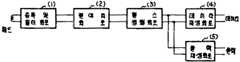
제3도는 본 발명 장치의 개략적인 구성을 나타낸 블럭도,3 is a block diagram showing a schematic configuration of an apparatus of the present invention;
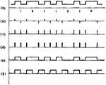
제4도는 제3도 각 부분의 신호 파형도.4 is a signal waveform diagram of each part of FIG.
* 도면의 주요부분에 대한 부호의 설명* Explanation of symbols for main parts of the drawings
1 : 증폭 및 필터 회로 2 : 절대치 회로1: amplification and filter circuit 2: absolute circuit
3 : 펄스 정형 회로 4 : 데이타 재생 회로3: pulse shaping circuit 4: data reproducing circuit
5 : 클럭 재생 회로5: clock regeneration circuit
본 발명은 자기카드에 기록된 위조 방지용 영구 신호를 판독해내는 방법 및 장치에 관한 것이다. 자기카드의 사용분야가 확대됨에 따라 그 위조 방지에 대한 대책이 절실하게 요구되어지고 있다.The present invention relates to a method and apparatus for reading out a forgery preventing permanent signal recorded on a magnetic card. As the field of use of magnetic cards expands, countermeasures against counterfeiting are urgently required.
그에 따른 방안으로서 자기카드의 자성재료 도포시에 영구적인 정보를 독특한 방법으로 기록시킴으로써 카드의 위조 또는 기록정보의 변경을 방지하는 방법이 본 출원인에 의해 새롭게 제시되었는바, 이를 간단히설명하면, 위조 방지 및 위조 감식을 위해 제조된 특수 자기카드에 있어서, 공지의 기저필름상에 고정정보를 함유할 수 있도록 고투자율의 특정의 자성재료를 부분적으로 도포하고, 상기 재료층 위에 통상의 자성재료를 그 윗면이 평평하게 도포하여, 카드 판독 창치의 자기헤드에 의한 카드의 감식시, 상기 특정 자성재료층의 존재부분과 비존재 부분의 잔류 자속 밀도 차이에 따른 헤드출력의 변화로 위조 감식을 수행할 수 있도록 하는 것이다.As a result, a new method has been newly proposed by the present applicant to prevent the forgery of the card or the change of the recording information by recording permanent information in a unique manner when applying magnetic material of the magnetic card. And a special magnetic card manufactured for counterfeit identification, in which a specific magnetic material having a high permeability is partially applied to contain a fixed information on a known base film, and a normal magnetic material is applied on the material layer. When applied flatly, upon identification of the card by the magnetic head of the card reading device, forgery identification can be performed by the change of the head output according to the difference in the residual magnetic flux density of the specific and nonexistent portions of the specific magnetic material layer. It is.
본 발명의 목적은 이와 같은 방법으로 제조된 위조 방지용 영구 신호가 기록된 자기카드로부터 영구 정보를 정확하게 읽어낼 수 있도록 하는 자기카드의 위조 방지용 영구 신호 판독 방법 및 장치를 제공하는데 있다.SUMMARY OF THE INVENTION An object of the present invention is to provide a method and apparatus for preventing counterfeit permanent signal reading of a magnetic card, which makes it possible to accurately read permanent information from a magnetic card on which an anti-counterfeiting permanent signal manufactured by such a method is recorded.
본 발명은 상기 목적을 달성하기 위해, 위조 방지용 영구 정보의 기록을 위하여 자기 기록층을 2층으로구성하되 그 중 한층은 투자율이 큰 물질을 부분적으로 도포하여 영구 정보를 형성시킨 자기카드의 영구 정보를 판독하는 방법에 있어서, 자기헤드로 상기 자기카드의 자화상태를 감지하고 그 신호를 증폭한 후 고주파 성분의 잡음을 제거하는 제1단계; 상기 제1단계 수행 후 신호의 방향에 관계없이 자속 밀도 변화 유무를 나타내도록 하는 제2단계; 상기 제2단계 수행 후의 신호를 TTL 레벨의 디지탈 신호로 변환시키는 제3단계; 및 상기 제3단계 수행 후의 디지탈 신호를 이용하여 영구 정보 신호를 재생하는 제4단계에 의해 수행되는 자기카드 위조 방지용 영구 신호의 판독 방법을 제공한다.In order to achieve the above object, the present invention comprises two layers of magnetic recording layers for recording permanent information for anti-counterfeiting, one of which is permanent information of a magnetic card formed by partially applying a material having a high permeability to form permanent information. 1. A method of reading a method comprising: a first step of sensing a magnetization state of a magnetic card with a magnetic head, amplifying the signal, and then removing noise of a high frequency component; A second step of indicating whether there is a change in magnetic flux density regardless of the direction of the signal after performing the first step; A third step of converting the signal after performing the second step into a digital signal having a TTL level; And a fourth step of reproducing the permanent information signal using the digital signal after the third step is performed.
또한, 위조 방지용 영구 정보의 기록을 위하여 자기 기록층을 2층으로 구성하되, 그 중 한층은 투자율이 큰 물질로 형성된 자기카드로부터 영구 정보를 판독해 내는 장치에 있어서, 자기카드의 자화상태를 감지하는 헤드; 상기 헤드로부터 출력된 신호를 증폭하고 고주파 성분의 잡음을 제거하는 증폭 및 필터 수단; 상기 증폭 및 필터 수단으로부터의 신호에 따라 방향에 관계없이 자속밀도 변화의 유무를 나타내도록 절대치 변환시키는 수단; 상기 절대치 변환 수단으로부터의 신호를 TTL 레벨의 디지탈 신호로 변환시켜 출력하는 펄스 정형 수단; 및 상기 펄스 정형 수단으로부터의 디지탈 신호를 이용하여 영구 정보 신호를 재생하는 재생수단으로 구성된 자기카드 위조 방지용 영구 신호의 판독 장치를 제공한다.In addition, the magnetic recording layer is composed of two layers for recording the anti-counterfeiting permanent information, one of which is a device that reads the permanent information from the magnetic card formed of a material having a high permeability, and detects the magnetization state of the magnetic card. Heads; Amplification and filter means for amplifying the signal output from the head and removing noise of high frequency components; Means for converting an absolute value according to the signal from the amplifying and filtering means to indicate the presence or absence of a change in magnetic flux density regardless of the direction; Pulse shaping means for converting and outputting a signal from said absolute value converting means into a digital signal of a TTL level; And reproducing means for reproducing the permanent information signal using the digital signal from the pulse shaping means.
이하 첨부된 도면을 참고로 하여 본 발명의 일실시예를 상세히 설명하기로 한다.Hereinafter, an embodiment of the present invention will be described in detail with reference to the accompanying drawings.
본 발명의 판독 대상이 되는 자기카드의 일예는 제1도에서 보인 바와 같이, 자성 재료 2의 유무로써 영구 정보가 기록되도록 한다. 이 경우, 자성 재료 1은 일반적으로 사용되는 자기기록 매체이고 상기 재료 2는 투자율이 매우 큰 물질이기 때문에 이러한 카드의 판류 자속 밀도는 제2도의 (a)와 같이 분포된다. 제2도의 (b)는 이것을 자가헤드로 읽었을때 얻어지는 일실시예 신호형태이다. 여기에서 정보의 기록방식은ISO 3554 표준규격에 의한다.One example of the magnetic card to be read of the present invention is to allow permanent information to be recorded with or without
본 발명은 전술한 카드로부터 얻은 미세신호를 F2F 형태의 디지탈 신호로 만들어 주는 위조 방지용 영구신호 판독 방법 및 장치에 관한 것으로서, 그 구성을 제3도에 블록도로 나타내었다.The present invention relates to a method and apparatus for reading a permanent signal for preventing forgery, which makes a microsignal obtained from the above-described card into a digital signal in the form of F2F. The configuration is shown in FIG.
도면에 도시한 바와 같이 본 발명의 자기카드 위조 방지용 영구 신호 판독장치는 제1도에 도시한 바와같은 독특한 방식으로 제조된 자기카드의 자화상태를 감지해 내는 공지의 자기헤드와, 상기 헤드에 연결되어 입력되는 신호를 증폭하고 고주파 성분의 잡음을 제거하는 증폭 및 필터 회로(1)와, 상기 증폭 및 필터회로의 출력단에 연결되어 입력되는 신호의 방향에 관계없이 자속 밀도 변화의 유무를 나타내도록 변환시키는 절대치 회로(2)와, 상기 절대치 회로에 연결되어 입력되는 신호를 TTL 레벨의 디지탈 신호로 변환시키는 펄스 정형 회로(3)와, 상기 펄스 정형 회로의 출력단에 각각 연결되어 그 디지탈 신호로부터 데이타를 재생하는 토글회로(4) 및 클럭신호를 재생하는 클럭 재생 회로(5)로 구성되어 있다.As shown in the figure, the permanent signal reading device for preventing the magnetic card forgery of the present invention includes a known magnetic head for detecting the magnetization state of a magnetic card manufactured in a unique manner as shown in FIG. An amplification and
이제, 상기한 바와 같은 자기카드로부터 영구 정보를 판독해내는 과정을 제4도를 참조하여 설명하면 다음과 같다.Now, the process of reading the permanent information from the magnetic card as described above will be described with reference to FIG.
먼저, 카드에 기록되어 있는 자기정보는 상기 헤드에 의해 전기적인 신호로 바꾸어진다. 이 신호는 수mV 단위이고 통상적으로 잡음도 섞여있다. 따라서 이 신호를 적당한 크기로 증폭해주고 고주파 성분의 잡음도 제거해 주어야 한다. 이 기능은 상기 제3도의 증폭 및 필터 회로(1)에 의해 이루어진다. 이때 신호의 형태는 제4도의 (b)와 같이 된다. 제4도의 (a)는 F2F 방식으로 기록된 자기카드의 잔류 자속 밀도와 기록 데이타를 나타낸 것이다.First, the magnetic information recorded on the card is converted into an electrical signal by the head. This signal is in the order of a few mV and is usually mixed with noise. Therefore, it is necessary to amplify the signal to an appropriate size and to remove noise of high frequency components. This function is achieved by the amplification and
상기 제4도 (b)의 펄스형태 신호는 자속밀도의 변화를 나타낸 것으로서, 이 신호가 상기 제3도의 절대치 회로(2)를 통과하게 되면 제4도의 (c)와 같은 신호가 얻어진다. 이 신호는 방향에 관계없이 자속밀도의 변환의 유무를 나타내주는 것이다. 그리고 나서 이 신호를 TTL 레벨의 디지탈 신호로 바꾸어 주기 위하여상기 펄스 정형 회로(3)를 통과시키면 제4도의 (d)와 같은 디지탈 펄스열을 얻을 수 있다. 이 펄스열은 상기 제3도의 데이타 재생 회로(4)와 클럭재생 회로(5)로 출력되는대, 이 신호로부터 원래 쓰여진 데이타와 동기클럭을 얻을 수 있다. 데이타 재생 회로(4)는 들어오는 펄스에 의해 토글(toggle) 동작을 하는 회로로 구성된다. 즉, 이 펄스들이 자속일도의 전이(transition)에 해당하므로 디지탈 신호의 상태천이로 변환시켜 주는 것이다. 그리면 한주기 내에서의 상태변화 유무로서 데이타값(0 또는 1)을 판변할 수 있는 F2F형태의 신호를 얻을 수 있는 것이다. 클럭 재생 회로(5)는 데이타 신호와 동기되어 데이타 값을 판별하는데 기준이 되는 클럭을 발생시키는 회로로서, 단안정 멀티바이브레이터(multi-vibrator) 회로로 구성되며, 제4도의 (d)신호가 트리거 입력으로 사용된다. 이때 상기 멀티바이브레이터 회로는 한 주기에 한번만 트리거 되도록 설계한다.The pulse shape signal of FIG. 4 (b) shows a change in magnetic flux density. When this signal passes through the
이로부터, 제4도 (e)와 같은 데이타 신호(f)와 같은 클럭신호를 얻게 된다. 그러면 그 후단에 연결되는CPU(도시하지 않았음)에서 이 두 신호를 동시에 읽어들임으로써 상기한 바와 같은 자기카드에 기록된 영구 정보를 정화하게 판독할 수 있게 된다.From this, the same clock signal as that of the data signal f as shown in FIG. Then, by reading these two signals simultaneously from the CPU (not shown) connected to the rear end, it is possible to cleanly read the permanent information recorded on the magnetic card as described above.
본 발명은 상기와 같이 구성되고 동작함으로써, 자기카드내에 독특한 방식으로 기록된 영구 정보를 정확하게 판독해 낼 수 있어 자기카드의 위조를 효과적으로 방지시킨다.The present invention is constructed and operated as described above, so that the permanent information recorded in a unique manner in the magnetic card can be accurately read, thereby effectively preventing the forgery of the magnetic card.
Claims (4)
Translated fromKoreanPriority Applications (1)
| Application Number | Priority Date | Filing Date | Title |
|---|---|---|---|
| KR1019890008241AKR920005875B1 (en) | 1989-06-15 | 1989-06-15 | Reading method and device for magnetic card |
Applications Claiming Priority (1)
| Application Number | Priority Date | Filing Date | Title |
|---|---|---|---|
| KR1019890008241AKR920005875B1 (en) | 1989-06-15 | 1989-06-15 | Reading method and device for magnetic card |
Publications (2)
| Publication Number | Publication Date |
|---|---|
| KR910001722A KR910001722A (en) | 1991-01-31 |
| KR920005875B1true KR920005875B1 (en) | 1992-07-23 |
Family
ID=19287124
Family Applications (1)
| Application Number | Title | Priority Date | Filing Date |
|---|---|---|---|
| KR1019890008241AExpiredKR920005875B1 (en) | 1989-06-15 | 1989-06-15 | Reading method and device for magnetic card |
Country Status (1)
| Country | Link |
|---|---|
| KR (1) | KR920005875B1 (en) |
Families Citing this family (1)
| Publication number | Priority date | Publication date | Assignee | Title |
|---|---|---|---|---|
| KR20020033382A (en)* | 2000-10-31 | 2002-05-06 | 전창오 | Magnetic card having magnetic double layer, and method for manufacturing the same |
- 1989
- 1989-06-15KRKR1019890008241Apatent/KR920005875B1/ennot_activeExpired
Also Published As
| Publication number | Publication date |
|---|---|
| KR910001722A (en) | 1991-01-31 |
Similar Documents
| Publication | Publication Date | Title |
|---|---|---|
| ATE6104T1 (en) | PROCEDURE FOR CHECKING THE READING OF AN AUDIO RECORDING WITH THE ASSISTANCE OF AN ADDITIONAL SIGNAL TO THIS RECORDING. | |
| KR100261196B1 (en) | Apparatus for using window signal generators to enable detection of header information such as an address mark | |
| US4137504A (en) | Digital filter | |
| TW218942B (en) | ||
| JPH05159454A (en) | Address information detecting device for magnetic disk recording medium | |
| KR920005875B1 (en) | Reading method and device for magnetic card | |
| CA1059238A (en) | Code converter | |
| KR940000974B1 (en) | Digital signal processing circuit | |
| KR910008433B1 (en) | Method and apparatus for reading permanent signals for preventing magnetic card forgery | |
| JPS61214278A (en) | Information reproducing system | |
| JP2891592B2 (en) | Servo information extraction device, servo mark detection device, and window generation device | |
| JPH0127490B2 (en) | ||
| JP2847527B2 (en) | Magnetic recording and reading method and apparatus for magnetic recording medium | |
| US5583708A (en) | Circuit for detecting unrecorded portion of recording medium | |
| JP2699960B2 (en) | Information reproducing apparatus and information reproducing method | |
| US5181196A (en) | Erase mark detecting circuit for detecting an erase mark superimposed on data recorded on a sector of an optical recording medium | |
| US5436881A (en) | Method and apparatus for detecting pulse signal for generating clock from recording medium | |
| JP2958667B2 (en) | High-density magnetic recording reading method | |
| JPH0644331B2 (en) | Peak detection circuit | |
| JPS6224357Y2 (en) | ||
| KR970707541A (en) | Playback circuit | |
| JPS63311672A (en) | Dropout detection circuit | |
| JPH04360070A (en) | magnetic recording and reproducing device | |
| JPS6288108A (en) | Signal regeneration circuit of magnetic disk device | |
| JPS6286587A (en) | Magnetic head positioning system for floppy disk device |
Legal Events
| Date | Code | Title | Description |
|---|---|---|---|
| A201 | Request for examination | ||
| PA0109 | Patent application | St.27 status event code:A-0-1-A10-A12-nap-PA0109 | |
| PA0201 | Request for examination | St.27 status event code:A-1-2-D10-D11-exm-PA0201 | |
| R17-X000 | Change to representative recorded | St.27 status event code:A-3-3-R10-R17-oth-X000 | |
| PG1501 | Laying open of application | St.27 status event code:A-1-1-Q10-Q12-nap-PG1501 | |
| E902 | Notification of reason for refusal | ||
| PE0902 | Notice of grounds for rejection | St.27 status event code:A-1-2-D10-D21-exm-PE0902 | |
| P11-X000 | Amendment of application requested | St.27 status event code:A-2-2-P10-P11-nap-X000 | |
| P13-X000 | Application amended | St.27 status event code:A-2-2-P10-P13-nap-X000 | |
| G160 | Decision to publish patent application | ||
| PG1605 | Publication of application before grant of patent | St.27 status event code:A-2-2-Q10-Q13-nap-PG1605 | |
| E701 | Decision to grant or registration of patent right | ||
| PE0701 | Decision of registration | St.27 status event code:A-1-2-D10-D22-exm-PE0701 | |
| PR1002 | Payment of registration fee | St.27 status event code:A-2-2-U10-U11-oth-PR1002 Fee payment year number:1 | |
| GRNT | Written decision to grant | ||
| PR0701 | Registration of establishment | St.27 status event code:A-2-4-F10-F11-exm-PR0701 | |
| PR1001 | Payment of annual fee | St.27 status event code:A-4-4-U10-U11-oth-PR1001 Fee payment year number:4 | |
| FPAY | Annual fee payment | Payment date:19980616 Year of fee payment:7 | |
| PR1001 | Payment of annual fee | St.27 status event code:A-4-4-U10-U11-oth-PR1001 Fee payment year number:7 | |
| LAPS | Lapse due to unpaid annual fee | ||
| PC1903 | Unpaid annual fee | St.27 status event code:A-4-4-U10-U13-oth-PC1903 Not in force date:19990724 Payment event data comment text:Termination Category : DEFAULT_OF_REGISTRATION_FEE | |
| PC1903 | Unpaid annual fee | St.27 status event code:N-4-6-H10-H13-oth-PC1903 Ip right cessation event data comment text:Termination Category : DEFAULT_OF_REGISTRATION_FEE Not in force date:19990724 | |
| PN2301 | Change of applicant | St.27 status event code:A-5-5-R10-R13-asn-PN2301 St.27 status event code:A-5-5-R10-R11-asn-PN2301 | |
| R17-X000 | Change to representative recorded | St.27 status event code:A-5-5-R10-R17-oth-X000 | |
| PN2301 | Change of applicant | St.27 status event code:A-5-5-R10-R13-asn-PN2301 St.27 status event code:A-5-5-R10-R11-asn-PN2301 | |
| PN2301 | Change of applicant | St.27 status event code:A-5-5-R10-R13-asn-PN2301 St.27 status event code:A-5-5-R10-R11-asn-PN2301 | |
| PN2301 | Change of applicant | St.27 status event code:A-5-5-R10-R13-asn-PN2301 St.27 status event code:A-5-5-R10-R11-asn-PN2301 | |
| P22-X000 | Classification modified | St.27 status event code:A-4-4-P10-P22-nap-X000 |